
J. Cent. South Univ. (2019) 26: 916-924
DOI: https://doi.org/10.1007/s11771-019-4060-4

Failure analysis study of railway draw-hook coupler
Moharram MOHAMMADI, Armin RAHMATFAM, Mohammad ZEHSAZ, Soran HASSANIFARD
Department of Mechanical Engineering, University of Tabriz, Tabriz, Iran
 Central South University Press and Springer-Verlag GmbH Germany, part of Springer Nature 2019
Abstract: Failure analysis of railway draw-hook coupler was carried out. The nondestructive testing method was undertaken on some failed couplers in service to designate critical areas of a coupler. Draw-Hook coupler is used to connect with the same hook coupler or automatic coupler. The influence of each connection types on the coupler strength in this study was discussed. A numerical stress analysis using FEM was performed, and many approaches including critical plane approach were carried out on fatigue life prediction of coupler under different conditions. The results of the proposed fatigue criterion and fatigue life predictions, as well as static numerical analysis, are validated with experimental results.
Key words: draw-hook coupler; multi-axial fatigue; critical plane approach; life prediction; static fracture force
Cite this article as: Moharram MOHAMMADI, Armin RAHMATFAM, Mohammad ZEHSAZ, Soran HASSANIFARD. Failure analysis study of railway draw-hook coupler [J]. Journal of Central South University, 2019, 26(4): 916�C924. DOI: https://doi.org/10.1007/s11771-019-4060-4.
1 Introduction
Rail transportation plays a strategic role in transport network of countries, hence sufficient safety factor for train parts must be considered. Couplers are one of the vital parts for train as they are used to connect wagons together, as well as for connection wagons to locomotive to transfer load or passengers. Hook coupler can only transfer tensile load received by adjacent wagons. In designing of coupler, two factors must be considered: 1) In order to avoide train derailment and other dangers during journey, couplers must have sufficient strength and safety. 2) For connection or disconnection of couplers to be done readily by railway workers, the using of couplers must be simple [1, 2].
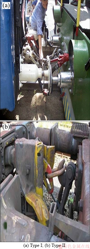
Figure 1 Connection types of draw-hook coupler:
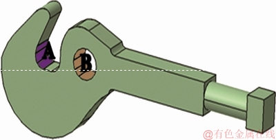
Figure 2 Positions of applied force on coupler
Figure 1 shows the connection types of draw- hook coupler. In Figure 1(a), the connection of two draw-hook couplers is indicated and Figure 1(b) shows the connection between a draw-hook with automatic coupler.
The connection between two draw-hook couplers (Figure 1(a)) is done by specific coupling system [3]. This coupling system connects the A and B regions of hook coupler to B and A regions of its adjacent hook coupler respectively (Figure 2). In this connection type of couplers, couplers can bear applied longitudinal load on the two regions A and B as identified in Figure 2, this case is identified as type I connection of coupler in present study. For connection between the draw-hook with automatic coupler (Figure 1(b)), draw-hook can only bear applied load on the one region A as identified in Figure 2, and in present study this case is identified as type II connection of coupler.
Draw-hook couplers are manufactured of cast steel with specified chemical composition prescribed in international union of railways (UIC) standards. However, there are some studies and proposals regarding the determining coupler forces and failure analysis, but there is no study about draw-hook coupler analysis. MARTIN et al [4] have discussed methods of analysis for determining the coupler forces in their researches in 1967. INFANTE et al [5] have studied the failure analysis of cast steel railway coupling in 2003. Determination of lifetime for railway carriage automatic coupler SA-3 has been studied by DAUNYS et al in 2005 [6]. MOUSAVI et al [7] have studied the failure analysis of automatic coupler SA-3 in 2007, which had failed in service and resulted in derailment. SCHU et al [8] have studied the failure analysis of railroad coupler of AAR type E in 2011. They have suggested a modified version of the automatic coupler knuckle of which the fatigue lifetime has been increased with the new design by maximum 8.3 and minimum 2.4 times.
2 Introduction to manufacturing and composition of draw-hook coupler
The hook test samples in one quarter scale of its standard size indicated in Figure 3 prescribed in UIC 520 were made to carry out fatigue and static experimental tests [9].
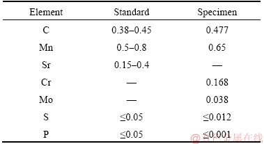
The couplers were normalized after production processes. Table 1 gives the results of chemical analysis performed on samples material compared to the standard prescriptions [10]. Some material properties of investigated coupler are given in Table 2 [11, 12]. In order to designate coupler critical areas, Nondestructive testing method was carried out on some failed couplers in service. In most cases, the cracks were observed in the neighborhood of the regions as identified in Figure 4, but sometimes poor mechanical properties of coupler material or defect in casting process had resulted the cracks to be grown on the other regions too (Figure 5).
3 Loading of coupler
In order to determine lifetime in any structure such as draw-hook coupler, it is essential to know exact applied loading history, i.e., the sequence of loading levels, the number of cycle for each level etc. [6], however, in prediction of loading history, consideration of some approximations are inevitable. Depending on wagons number, loading weight, train speed and other parameters, the applied load on coupler will be different. Train velocity variations and shocks or sudden accelerations result in the acting force on couplers to be varied. Couplers are subjected to stresses above the material yield stress and under the yield stress. Therefore, the influences of low and high cycle fatigue must be considered in fatigue analysis of coupler.
As earlier mentioned, train speed oscillates around the target speed [13]. Speed oscillations are resulted from the variation of acting force on couplers. Depending on how train speed varies, the acting force on couplers and consequently, the lifetime of couplers will be different.
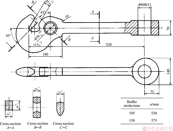
Figure 3 UIC standard prescribed dimensions for draw-hook coupler (Unit: mm)
Table 1 Chemical composition of investigated coupler and standard values (mass fraction, %)
3.1 Force calculation
Total force produced by locomotive engine is not going to act on the coupler, a part of the force is utilized to overcome the friction [8]. The acting force on each coupler is different from the others. In order to illustrate a numerical example, a train with 10 wagons and specifications given in Table 3 was considered [3, 14].
Figure 6 shows schematic of wagon with its acting forces. Couplers acting force of the train corresponding to acceleration from 0 to 60 km/h have studied and the maximum experienced coupler force in acceleration period of train was calculated about 230 kN for specified train [3]. Couplers acting force in this period are much more than the couplers force after reaching the train to target speed. The speed variations of train result acting force on couplers to be varied during journey, therefore influence of this phenomenon on coupler lifetime must be studied too. In order to determine applied forces on a coupler during journey, wagon connected to locomotive body was considered as Shown in Figure 6. Applying equilibrium equation on the model, the result becomes as:
 (1)
(1)
The traction force of locomotive (u) and resistance force of each wagon (fp) can be determined as [12]:
 (2)
(2)
 (3)
(3)
Figure 7 indicates the coupler connected to locomotive force with respect to some velocity variations during train journey for the illustrated train.
Table 2 Material properties of investigated coupler
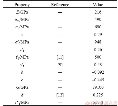
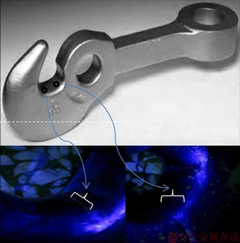
Figure 4 NDT tests of failed coupler
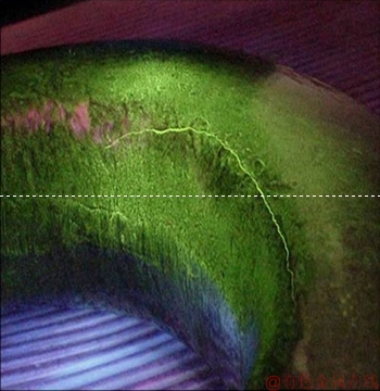
Figure 5 Growth of crack on surface of a coupler
Table 3 Technical characteristics of train vehicles
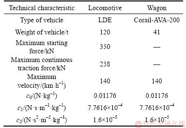
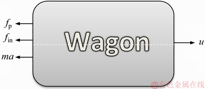
Figure 6 Schematic of wagon
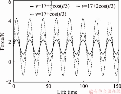
Figure 7 Coupling connected to locomotive force variations due to train speed oscillations
3.2 Stress analysis of draw-hook coupler
According to UIC 520, the minimum breaking strength of draw-hook coupler shall be 1000 kN [9]. As it was mentioned, draw-hook coupler is used in each connection types I and II (Figure 1). In order to conform static strength of coupler, numerical stress analysis was carried out and results from experimental tests in type II connection of coupler could validate computed numerical results. Experimental coupler samples were made in one quarter scale of standard size, therefore, structural analysis was carried out on draw-hook coupler for one quarter scale of UIC prescribed coupler size (Figure 3).
The finite element code ABAQUS was used and the type of element was solid C3D8R hexahedral. The final numerical model has 9039 nodes and 7148 elements. Figures 8 and 9 indicate the von-Mises stress distribution on the coupler under the applied static fracture force in connection types I and II, respectively.
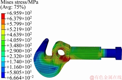
Figure 8 Von-Mises stress distribution of coupler in connection type I under 88.3 kN applied force
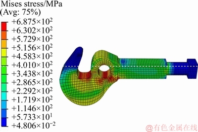
Figure 9 Von-Mises stress distribution of coupler in connection type II under 66.7 kN applied force
The FEM analysis shows that, the coupler has higher strength in connection type I compared to type II connection of coupler. The static fracture force of sample coupler in connection type II was obtained about 69 kN from experimental results (Figure 10).
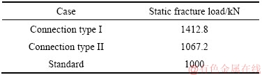
Experimental coupler samples were manufactured in one quarter scale of coupler size prescribed in UIC. With regarding to relation between stress and area, and in order to find the stress in identical value for standard size coupler compared to experimental samples, the applied force must be sixteen times bigger than the applied force on the experimental samples. Table 4 gives static fracture forces of draw-hook coupler in both connection types compared to standard value for the coupler with UIC prescribed size.
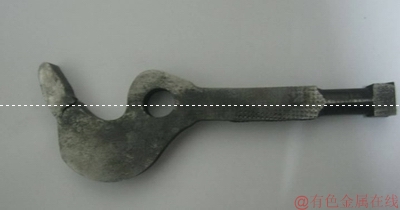
Figure 10 Failed coupler under static test
Table 4 Static fracture forces of draw-hook coupler
4 Fatigue analysis
It was found that fatigue is the dominant failure mechanism of coupler [7]. Experienced stresses on the coupler necessitate high and low cycle fatigue studying of coupler, therefore damage factor of each high cycle fatigue (HCF) and low cycle fatigure (LCF) should be considered in coupler fatigue analysis [6].
 (4)
(4)
In order to predict lifetime of coupler some approaches as given in Table 5 were utilized. Findley approach is carried out for predicting high cycle fatigue life. Experienced stresses of couplers were multiaxial, therefore, multiaxial fatigue approaches were used in present study to fatigue lifetime prediction of coupler. Experimental tests in type II connection of coupler were carried out to validate numerical results. Experimental coupler samples were manufactured in one quarter scale of coupler size prescribed in UIC (Figure 11). With regarding to relation between stress and area, and in order to find the stress in identical value for standard size coupler compared to experimental samples, the applied force must be sixteen times bigger than applied force on the experimental samples. Table 6 gives the results obtained from experimental tests compared to predicted results in connection type II for UIC prescribed coupler size, as well as these results are shown for type I connection of coupler in Table 7.
Critical plane approaches have been found to be applicable to both proportional and non- proportional loading conditions [15]. Modified Fatemi-Socie damage parameter is used in this paper [11]. In this method, critical plane is identified as the plane which the damage parameter dsgiven by the product  is maximum and life estimated based on accumulated damage on this plane. For SWT critical plane approach, critical plane was considered as the plane in which damage parameter dt given by product ��a��a is maximum, and life was estimated based on accumulated damage on this plane [11]. As well as in Findley model critical plane is identified as the plane in which the damage parameter given by
  is the maximum [16]. Figure 12 reports the flowchart summarizing the algorithm used in this present study as being used to determine fatigue lifetime based on Fatemi-Socie and SWT critical plane approaches.
Table 5 List of used fatigue life prediction approaches
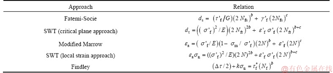
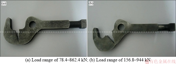
Figure 11 Failure of couplers under fatigue tests:
Table 6 Predicted versus experimental fatigue lives for coupler in connection type II
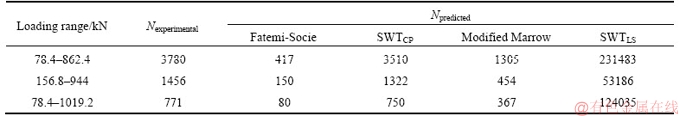
Table 7 Predicted fatigue lives for coupler in connection type I
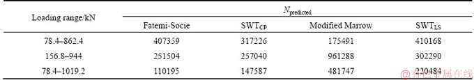
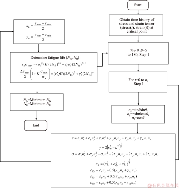
Figure 12 Flowchart summarizing algorithm used to determine fatigue lifetime based on Fatemi-Socie and SWT critical plane approaches
Figures 13 and 14 show the predicted life for draw-hook coupler by SWT and Fatemi-Socie critical plane approaches at stress ratio R=0 in types I and II connection of coupler respectively. The cracks are often created on surface of coupler in the effect of train shocks, sudden accelerations or high longitudinal load due to the excessive train load. From the nondestructive tests observations, it was found that, in most cases the cracks were created in the neighborhood of the regions where stress has maximum magnitude. Experimental coupler samples were failed under fatigue testing from the same regions as identified in Figure 4, where the NDT validates, fractured areas of experimental samples (Figure 11) were critical regions of coupler.
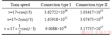
Fatemi-Socie model for engineering components or structures which are subjected to shear stresses, and SWT model for structures which are subjected to normal stresses often present good life predictions. For investigated couplers because the normal stresses and strains are dominant, SWT critical plane approach has better life predictions compared to other ones. Results show, Fatemi-Socie approach provides conservative life prediction. In order to predict high cycle fatigue life, Findley critical plane approach is carried out. For illustrating one numerical example, the explained 10 wagons train with acting force during journey as indicated in Figure 7 was considered. Table 8 gives high cycle fatigue life of coupler relative to speed variations.Results imply that, coupler lifetime would be infinite if it was only exposed to high cycle fatigue damage, and the same result was found for coupling joint [17].
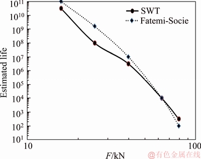
Figure 13 Predicted fatigue lives of coupler in connection type I at R=0
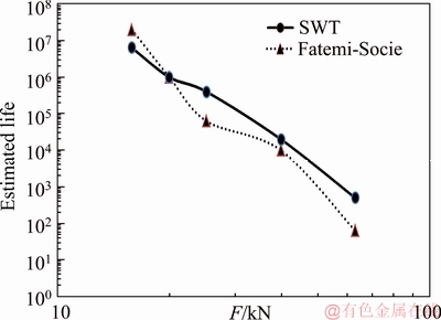
Figure 14 Predicted fatigue lives of coupler in connection type II at R=0
Table 8 Predicted life of coupler in HCF regime with Findley critical plane approach
5 Conclusions
1) Couplers acting force in train acceleration period are much higher than the train couplers force after reaching the train velocity to target speed.
2) Draw-hook coupler has higher static strength, about 1.32 times at connection type I compared to type II connection of coupler.
3) Results from NDT show that fatigue is the dominant failure mechanism of coupler. The cracks on surface of coupler result in the decrease of coupler fracture force and it might result in train derailment during journey.
4) For draw-hook coupler, since the experienced normal stress and strain are dominant, the SWT critical plane approach provides better life predictions compared to other ones in low cycle fatigue regime. Fatemi-Socie approach has conservative life predictions for draw-hook coupler.
5) The coupler has longer fatigue life at connection type I compared to type II connection of coupler.
6) If the coupler is only subjected to the loads of velocity variations during journey and it is not exposed to shocks or possible structural defects etc., the lifetime of coupler would be infinite.
References
[1] GAO G J, CHEN W, ZHANG J, DONG H P, ZOU X, LI J, GUAN W Y. Analysis of longitudinal forces of coupler devices in emergency braking process for heavy haul trains [J]. Journal of Central South University, 2017, 24(10): 2449�C2457.
[2] LIU P F, WANG K Y. Dynamic performance of heavy-haul combined train applying emergency braking on straight line [J]. Journal of Central South University, 2017, 24(8): 1898�C1908.
[3] CERNESCU A, DUMITRU I, FAUR N, BRANZEI N, BOGDAN R. The analysis of a damaged component from the connection system of the wagons [J]. Engineering Failure Analysis, 2013, 29: 93�C107.
[4] MARTIN G C, HAY W W. Method of analysis for determining the coupler forces and longitudinal motion of a long freight [D]. Urbana: University of Illinois, 1967.
[5] INFANTE V, BRANCO C M, BRITO A S, MORGADO T L. A failure analysis study of cast steel railway couplings used for coal transportation [J]. Engineering Failure Analysis, 2003, 10: 475�C489.
[6] DAUNYS M, PUTNAITE D. Determination of lifetime for railway carriage automatic coupler SA-3 [J]. Mechanika, 2005, 52: 5�C9.
[7] MOUSAVI ZADEH NOUGHABI S M, DEHGHANI K, POURANVARI M. Failure analysis of automatic coupler SA-3 in railway carriages [J]. Engineering Failure Analysis, 2007, 14: 903�C912.
[8] CHUNDURU S P, KIM M J, MIRMAN C. Failure analysis of railroad couplers of AAR type E [J]. Engineering Failure Analysis, 2011, 18: 374�C385.
[9] UIC Leaflet 520. Wagons, coaches and vans-Draw gear [S]. 2003.
[10] UIC Leaflet 825 O. Technical specification for the supply of draw hooks with nominal load equal to 250 kn, 600 kn or 1000 kn for tractive and trailing stock [S]. 1985.
[11] DAS J, SIVAKUMAR S M. An evaluation of multiaxial fatigue life assessment methods for engineering components [J]. International Journal of Pressure Vessels and Piping, 1999, 76: 741�C746.
[12] LIU Y. Stochastic modeling of multiaxial fatigue and fracture modeling [D]. Nashville: Vanderbilt University, 2006.
[13] KE B R, LIN C L, LAI C W. Optimization of train-speed trajectory and control for mass rapid transit systems [J]. Control Engineering Practice, 2011, 19: 675�C687.
[14] CHOU M, XIA X. Optimal cruise control of heavy-haul trains equipped with electronically controlled pneumatic brake systems [J]. Control Engineering Practice, 2007, 15(5): 511�C519.
[15] FATEMI A, SHAMSAEI N. Multiaxial fatigue: An overview and some approximation models for life estimation [J]. International Journal of Fatigue, 2011, 33: 948�C958.
[16] PARK J, NELSON D. Evaluation of an energy-based approach and a critical plane approach for predicting constant amplitude multiaxial fatigue life [J]. International Journal of Fatigue, 2000, 22: 23�C39.
[17] INFANTE V, DUARTE P, BRANCO C M. Fatigue analysis of railway coupling joint [J]. Engineering Failure Analysis, 2007, 14: 1175�C1184.
(Edited by HE Yun-bin)
���ĵ���
��·ǣ�����������ʧЧ����
ժҪ�����Ķ�ŷ���������ҹ㷺ʹ�õ���·ǣ���������������˹��Ϸ�������ʹ���е�һЩʧЧ�����������������ԣ���ȷ��������Ĺؼ�����ǣ�������������������ͬ�Ĺ���������Զ���������������������Ͷ������ǿ�ȵ�Ӱ�졣��������Ԫ������������ֵӦ�������������ٽ�ƽ�淨�ȶ��ַ����Բ�ͬ�������������ƣ����������Ԥ�⡣ͨ��ʵ������֤���������ƣ�ͱ���ƣ������Ԥ���Լ���̬��ֵ�����Ľ����
�ؼ��ʣ�ǣ���������������ƣ�ͣ��ٽ�ƽ�淽��������Ԥ�⣻��̬������
Received date: 2017-04-26; Accepted date: 2018-10-20
Corresponding author: Armin RAHMATFAM, PhD Candidate; Tel: +98-4133393060, Fax: +98-4133354153; E-mail: a.rahmatfam@ tabrizu.ac.ir
