J. Cent. South Univ. (2012) 19: 1353-1358
DOI: 10.1007/s11771-012-1149-4
Liquid film falling behaviour on horizontal circular cylinder
CHUNG Han-shik1, K. Wusiman2, KIM Seong-soo2, B. Nasan2,
H. Afrianto2, Hafizur Rehman2, CHOI Du-youl3, JEONG Hyo-min1
1. Department of Energy and Mechanical Engineering, The Institute of Marine Industry,
GyeongSang National University, TongYoung, GyeongNam 650-160, Korea;
2. Department of Mechanical and Precision Engineering, GyeongSang National University,TongYoung, GyeongNam 650-160, Korea;
3. Fluid and Thermal Engineering Co., Ltd., GimHae-si, GyungNam 621-843, Korea
? Central South University Press and Springer-Verlag Berlin Heidelberg 2012
Abstract: The flow pattern behaviour of falling liquid film over three horizontal cylinders was evaluated. These flows can take three forms: discrete droplets, individual jets, and continuous sheet, and special attention is paid to the effects of the physical properties and geometrical parameters of the first two forms (droplets and jets) because these forms are more important in heat-transfer behaviour and less research has been published for these forms. The flow modes and experimental results were successfully compared with previous experimental literatures, and also the effects of liquid flow rate, tube diameter, and tube spacing on departure site spacing, in both drop and jet modes, were evaluated in the low Galileo number and high viscosity fluid (cooking oil), to help developing criteria for determining falling film modes and their transitions, and to understand the heat transfer characteristics associated with each mode.
Key words: falling film; flow mode; cylinder
1 Introduction
A liquid film flowing over horizontal cylinders is of great importance as a high rate of heat transfer exists between the falling liquid film and the horizontal cylinders. For this reason, falling film is widely used in chemical and food process industries and in refrigeration equipment where high rates of heat transfer are important. In spite of the widespread application, the mechanism of heat transfer with a liquid film falling freely between adjacent horizontal tubes is still poorly explored. Furthermore, experimental works concerning heat transfer reported in the literature did not include systematically variations of each important parameter. In particular, the flow patterns of the liquid have been rarely included in heat transfer considerations. Since flow patterns influence heat transfer process on the interface of the tube, it would be necessary to include them into heat transfer considerations. For these reasons, the boundaries of flow patterns and arrangement of liquid falling sites in droplet and column modes should be known. Some of relevant references about flow patterns mentioned that basically three-flow modes can be observed when liquid films flow past horizontal cylinders, namely: 1) droplet mode, 2) jet or column mode, and 3) sheet mode.
The flow patterns observed in falling-film heat exchangers have been idealized and described by MITROVIC [1], as shown in Fig. 1.
Additional work on the flow mode is given by HU and JACOBI [2] for the flow characteristics and mode transitions for wide ranges of flow rate and fluid properties. They described the transitions between falling film modes in terms of competing flow mechanisms: inertia dominated flows take the sheet mode, gravity or surface-tension dominated flows take the droplet mode, and the jet mode results when these mechanisms compete [3]. The essential mechanism is mainly used by present researchers for exploring the falling film behaviours on several industrial working fluids.
MITROVIC [1] investigated the falling film, flow mode and transitions of adiabatic and non-phase change film for plain tubes and found that transition from the droplet mode to the jet mode occurred at Reynolds numbers between 150 and 200. The transition from jet mode to the sheet mode occurred at Reynolds numbers between 315 and 600. It seems to give us much information about the performance of falling film, but there are still lots of ambiguities about whether the fluid properties and dimensions of experimental device impact on flow patterns or not.
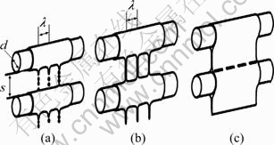
Fig. 1 Idealized intertube of falling film modes: (a) Droplet mode; (b) Jet mode; (c) Sheet model
Hence, studies about flow transition of the falling film modes have attracted the attention of many researchers. At the present exploration, the wavelength �� is widely used and becomes a very important key to understand and describe the behaviour of the falling film as well as flow modes which is shown in Fig. 1, and all the characteristics of heat transfer performance in the droplet and jet modes are also associated with the wavelength ��. The wavelength can be calculated according to LIENHARD and WONG [4]: The distance between two streams of droplets or jets is characterised by
 (1)
(1)
where �� is the wavelength; g is the gravity; �� is the density; �� is the surface tension; D is the cylinder diameter.
This behaviour appears to be related to the Taylor instability. For inviscid, incompressible fluids, BELLMAN and PENNINGTON [5] found the so-called critical and most dangerous Taylor wavelength to be given by
 (2)
(2)
where ��c represents the wavelength of the shortest unstable disturbance; whereas, ��d is the disturbance length that grows most rapidly and is expected to appear in application.
YUNG et al [6] concluded that for low-viscosity liquids, like water, ethyl alcohol and ammonia, the instability wavelength most likely to appear at the interface is
 (3)
(3)
For liquids on a horizontal tube, they found that n=2 best fits the experimental data, but for thick liquid layers they recommend n=3. For high-viscosity liquids, TAGHAVI and DHIR [7] found that �� is larger than that for low-viscosity liquids. These results are also not satisfied because they did not clearly mention the comparison of different fluids, especially, the result of high-viscosity fluid.
Very recently, AMBRUSTER and MITROVIC [8] provided a correlation for jet spacing, and most of other references focused on this correlation and compare their result with the correlation. Most of results get a good agreement with this correlation, even though the correlation is based on data from two fluids, water and isopropyl alcohol, and is reported to correlate their data within ��7.5%. Using the current nomenclature, the correlation can be written as
 (4)
(4)
This expression is somewhat unique, where it explicitly accounts for a flow rate effect on the jet spacing. There are not data provided for droplet spacing. It really needs experiment results of other fluids and comparison with the correlation.
HU and JACOBI [2, 9] studied the falling-film flow-mode transitions under adiabatic conditions for a variety of fluids, tube diameters, tube pitches and flow rates. They proposed that the flow-mode transition is coordinated with film Reynolds number (Re) and the Galileo number (Ga). The transition is defined among the three dominant modes (droplet, column and sheet) with two mixed mode zones (droplet�Ccolumn and column�Csheet). The corresponding four flow transitions among these five zones are given below for plain tubes and air velocity of 15 m/s. The transition is in either direction, as denoted by a double-headed arrow:
Droplet ?Droplet�CColumn:
Re=0.074Ga0.302 (5)
Droplet�CColumn ?Column:
Re=0.096Ga0.301 (6)
Column ?Column�CSheet:
Re=1.414Ga0.233 (7)
Column�CSheet ?Sheet:
Re=1.448Ga0.236 (8)
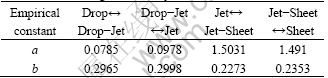
The falling-film flow-mode transitions have also been experimentally studied by MOHAMED [10]. He obtained the following correlation between the Reynolds number, Re, and Galileo number, Ga:
Re=aGab (9)
where a and b are the empirical constants, as given in Table 1.
So, there are not very reliable correlations for prediction of flow mode performances developed yet, also it is really hard and confused to choose the relative correlation for application. Hence, the present experiments are hopeful to enable some deeper understanding of flow phenomena concerning falling film on horizontal tubes at least in low Ga number and high viscosity fluids.
Table 1 Constants in MOHAMED��s correlation for change in flow mode of falling film over cylinder
2 Experimental apparatus
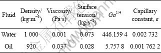
Figure 2 shows a photograph and a schematic view of the experimental apparatus used in this work. It consists of test liquid circulation systems, a test fluid feeder tank with a 0.5 mm slot, three test cylinders and a reservoir. The working fluid is pumped up from lower reservoir to the overflow feeder tank. Cooking oil is used as the test fluid. The comparison of properties between oil and water are given in Table 2.
Two valves were used to control the mass flow rate to study flow patterns. The measurement of mass flow rate is very critical and important for this experiment. Stopwatch and graduated cylinder were used to measure volume flow rate of outlet of the receive tank. This flow rate is equal to the falling film flow rate because of fluid continuity in the whole circulation system. The measurement of ��* is conducted by a digital camera to record flow pattern image as well as the known actual dimension of tube diameter at same time on the same picture, and then chart distance measurement software and the ratio of the image were employed to calculate the actual dimension of ��*. Because of using a reference image ratio to figure out ��*, the uncertainty in length is determined as ��1 mm.
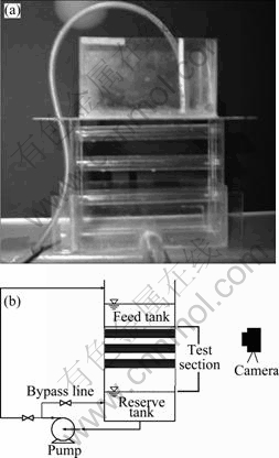
Fig. 2 Photograph (a) and schematic diagram (b) of experimental apparatus
Table 2 Comparison of physical properties between water and cooking oil
3 Result and discussion
3.1 Effect of Re number on flow patterns
Depending on the mass flow rate and physical properties of the liquid and geometric parameters, all main flow patterns of droplet and jet modes are studied in experiment, as shown in Fig. 3. The water film is usually roughed and wavy, while film of cooking oil shows very smooth and regular shapes.
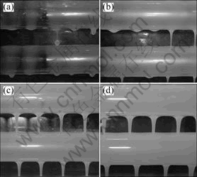
Fig. 3 Flow patterns of cooking oil at Ga1/4��5.76, d*=17.02 and s*=11.35: (a) Droplet, Re=0.4, ��*=10.59; (b) Drop-jet, Re=0.5, ��*=9.32; (c) Inline jet, Re=2.2, ��*=7.40; (d) Staggered jet, Re=2.9, ��*=8.43
In Fig. 4, the effect of Re number of falling film on the dimensionless departure site spacing ��* of three test cylinders is explored by controlling the test fluid volume flow rate. It is clearly shown that all ��* values at top, middle and bottom cylinders, are slightly decreased by increasing of Re over all testing range. For purpose of comparison, in this experiment, we also associated with Eq. (4) and extrapolated beyond the Ga1/4 range of this correlation, and plotted this result with dashed line. Because Eq. (4) is restricted to jet mode, the experimental results are compared just in jet mode. The results are also in general agreement with Eq. (4). In the droplet mode zone which appears at lower Re, the departure site of ��* between the three test cylinders is a little more sensitive than in jet mode, and ��* is small for the top cylinder, then it increases for middle and bottom cylinders at the same Re in droplet. So, it seems that the spatial placement of the cylinders also affects ��* in the droplet mode. It gets a quite good agreement that as Re��0, the droplet spacing ��* appears to approach the most dangerous Taylor wavelength as given by Eq. (2):  At the jet mode zone which appears at higher Re, ��* becomes to be insensitive to both Re and spatial placement. The ��* almost keeps the value between 8 and 10 over the whole jet mode zone, and also in this zone, inline jet happens at first as increasing the Re in wide range, and then staggered jet happens in a specially narrow zone which appears ��* much more different between three cylinders than inline jet, because the number of staggered jets appears less between the cylinders. The inline jet happens again after staggered jets with increasing Re. In the droplet-jet mixed transition zone, ��* of the drop and jet between the cylinders plays its own characteristics of droplet mode and jet modes, respectively. Predicted Re values of the drop-jet transition zone based on Eqs. (5) and (9) are Re=0.613 and 0.626, respectively, when using the cooking oil as test fluid, and the experiment result is in good agreement with the prediction.
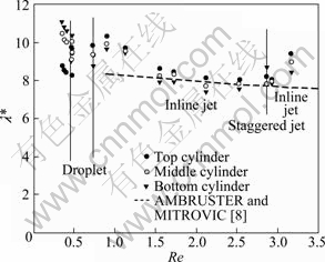
Fig. 4 Effect of film Reynolds number on dimensionless departure site spacing ��* of three cylinders for cooking oil with Ga1/4��5.76, d*=17.02 and s*=11.35
3.2 Effects of tube spacing s* and tube diameter d* on departure site spacing ��*
Figures 5 and 6 show the effect of tube spacing s* and tube diameter d* on the departure site ��* between the cylinders, respectively. In Fig. 5, it is indicated that the effect of tube spacing s* is a little more pronounced in drop mode than in jet mode. It has the tendency that ��* is increased with s* in droplet, and in jet mode, ��* becomes insensitive with increasing the tube spacing. This behaviour is quite congruent with the predictions already discussed in Fig. 4 about the tube spatial placement effects on ��*.
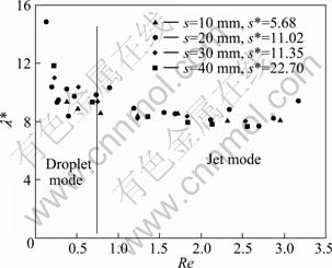
Fig. 5 Effect of tube spacing on dimensionless departure site spacing ��* on cylinder for fried cooking oil with Ga1/4��5.76 and d*=17.02
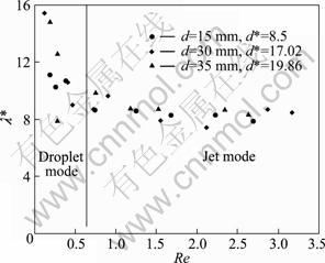
Fig. 6 Effect of tube diameter on dimensionless departure site spacing ��* on cylinder for fried cooking oil with Ga1/4��5.76 and s*=11.35
In Fig. 6, the results indicate that ��* is almost independent of the tube diameters in whole testing flow patterns. It is in good agreement with TANG et al [11] that ��* increases with r* but becomes insensitive to tube radius for r*>4 (d*>2). Compared with the effects of d* in the droplet, the tube spacing s* plays much weaker effect in the droplet mode. However, the results suggest that ��* becomes more sensitive to Re in droplet mode in these ranges of tube diameters, and Fig. 6 shows that ��* highly depends on Re in the droplet mode.
3.3 Effect of height of feeder h* on departure site spacing ��*
In most of prior works, the effect of the height from feeder tank to the first testing cylinder was not included when the flow patterns behaviour on horizontal cylinders was conducted. The flow patterns might be influenced by the height of feeder, because the initial velocity of the fluid arriving at the first testing cylinder from the slot of feeder tank is higher with larger feeder height, which also makes different velocities on every cylinder at different feeder heights.
From Fig. 7, it is indicated that the effect of feeder height is also more pronounced in the droplet modes. It is somewhat surprising that ��* decreases with increasing the feeder height in droplet. And ��* becomes independent of feeder height in jet mode. It can be interpreted that the viscosity is highly dominated in the jet mode and overcomes the influence of different velocities on the cylinders in higher viscosity fluid as cooking oil in jet mode.
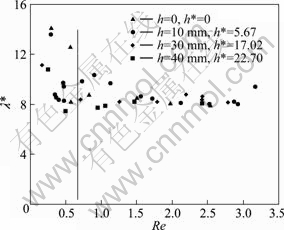
Fig. 7 Effect of feeder height on dimensionless departure site spacing ��* on cylinder for fried cooking oil with Ga1/4��5.76, d*=17.02 and s*=11.35
4 Practical significance
So, we can get the information from the experimental tests: The low Ga1/4 and high viscosity fluid as a oil plays quite much lower value of Re number in the flow patterns than the high Ga1/4 fluid as water (droplet��jet mode, Re from 0 to 600). In application of heat transfer behaviour for low Ga1/4 and high viscosity fluid, in droplet, we should conduct with shorter ��*, then more numbers of droplets and higher frequency droplets will happen between the cylinders, which helps increasing the local heat transfer coefficient because of impingement. From Fig. 6, ��* highly decreases with Re in droplet and then becomes insensitive in jet mode when d*>8.5. So, it is quite available to get the higher heat transfer coefficient by increasing a smaller mass flow rate (Re number) in droplet mode when the heat exchanger is designed. However, the spatial placement of cylinders also deeply affects ��* in droplet (Figs. 4 and 5), due to the fact that wetting characteristics of the flow are very important to the heat transfer performance. Furthermore, local dry-out can be a significant problem in operation. A large spacing between cylinders in droplet might lead to local film dry-out, so it is not a wise way to increase the tube spacing s* and tube diameter to get small ��* of falling film for increasing the heat transfer coefficient.
In jet mode, this kind of fluid as oil becomes weakly independent of Re, tube diameter d* and tube spacing, so we should consider about trying to increase the vertical spacing between the cylinders and tube diameter. Because the height of spacing increases, the fluid will gain slightly higher velocity, so the higher tube spacing helps the jets to strengthen the jet impingement area to increase the local heat transfer coefficient more, and also the higher velocity fluid flowing around the cylinder will increase the convective heat transfer more on the interface of cylinders. Both of them will allow the designed heat transfer exchanger to run more efficiently. For the parameter of tube diameter d*, increasing d* will not affect the jet mode flow behaviour (Fig. 6), but it can increase the heat transfer interface, and it also can help to increase the heat transfer efficient. However, the larger tube spacing and tube diameter lead to the bigger geometrical dimension problems of designed heat exchanger, and too high spacing causes some fluid droplets to slide down the tube leaving the area below, which makes the heating tube dry. This would make terrible heat transfer performance in heat exchanger.
The feeder height h affects the droplet mode and becomes independent in jet mode, so especially in droplets, the vertical movement of feeder tank will affect the heat transfer behaviour in heat exchanger.
5 Conclusions
1) The influences of Re, tube diameter d*, and feeder height h* on ��* are more pronounced in the discrete droplet. However, in jet mode, all ��* values have weak dependence on the parameters.
2) Both modes show that flow patterns are not significantly affected by tube spacing s*.
3) The departure site spacing ��* and effects of all parameters are successfully correlated to previous references.
4) Future research with other fluids exhibiting higher and lower Ga numbers would be helpful for furthering understanding in flow pattern characteristics.
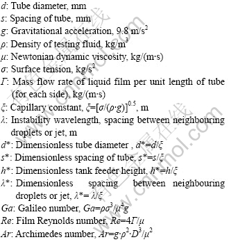
Nomenclature
Acknowledgements
This work is financially supported by New Product Development of Small and Medium Business Administration (SMBA) and funded by the Ministry of Education, Science and Technology (No. 2011-0021376) through the Basic Science Program of the National Research Foundation of Korea (NRF).
References
[1] MITROVIC J. Influence of tube spacing and flow rate on heat transfer from a horizontal tube to a falling liquid film [C]// Proceedings of the 8th International Heat Transfer Conference. San Francisco, 1986: 1949-1956.
[2] HU X, JACOBI A M. The intertube falling film: Part I-Flow characteristics, mode transitions, and hysteresis [J]. Heat Transfer, 1996, 118: 616-625.
[3] HU X, JACOBI A M. Departure-site spacing for liquid droplets and jets falling in thin-film heat exchangers [J]. ACRC CR9, 1997, Urbana, IL61801. 217: 333-3115.
[4] LIENHARD J H, WONG P T Y. The dominant useable wavelength and minimum heat flux during film boiling on a horizontal cylinder [J]. Heat Transfer, 1964, 86: 220-226.
[5] BELLMAN R, PENNINGTON R H. Effects of surface tension and viscosity on Taylor instability [J]. Appl Math, 1954, 12: 151-162.
[6] YUNG D, LORENTZ J, GANIC E N. Vapor/liquid interaction and entrainment in falling film evaporators [J]. Heat Transfer, 1980, 102: 20-25.
[7] TAGHAVI K, DHIR V K. Taylor instability in boiling, melting and condensation or evaporation [J]. Heat Mass Transfer, 1980, 23: 1433-1445.
[8] AMBRUSTER R, MITROVIC J. Heat transfer in falling film on a horizontal tube [C]// Proceedings of the National Heat Transfer Conference, 1995: 13-21.
[9] HU X, JACOBI A M. The intertube falling film: Part 2- Mode effects on sensible heat transfer to a falling liquid film [J]. Heat Transfer, 1996, 118: 626-633.
[10] MOHAMED A M I. Flow behaviour of liquid falling film on a horizontal rotating tube [J]. Experimental Thermal and Fluid Science, 2007, 31: 325-332.
[11] TANG J, LU Z, B. Yu-Chi. Droplet spacing of falling film flow on horizontal tube bundles [C]// Proceedings of the 18th International Congress of Refrigeration. Montreal, 1991: 474-478.
(Edited by YANG Bing)
Received date: 2011-09-14; Accepted date: 2011-12-26
Corresponding author: JEONG Hyo-min, Professor, PhD; Tel: +82-10-9548-3184, Fax: +82-55-772-9119; E-mail: hmjeong@gnu.ac.kr

