Adsorption structures of frothers at gas–liquid interface using DFT method
来源期刊:中南大学学报(英文版)2019年第3期
论文作者:陈建华 张一兵 李玉琼 张培新
文章页码:536 - 549
Key words:frother; water phase; gas–liquid interface; foaming; DFT
Abstract: Density functional theory (DFT) simulation was performed to investigate the adsorption mechanisms between frothers and gas–liquid interface. In water phase, the polar head group of the frother molecule was connected with water molecules by hydrogen bonding, while the non-polar group showed that hydrophobic property and water molecules around it were repelled away. The adsorption of water molecules on single frother molecule suggests that the complexes of α-terpineol-7H2O, MIBC-7H2O and DF200-13H2O reach their stable structure. The hydration shell affects both the polar head group and the non-polar group. The liquid film drainage rate of DF200 is the lowest, while α-terpineol and MIBC are almost the same. The adsorption layer of frother molecules adsorbed at the gas-liquid interface reveals that the α-terpineol molecules are more neatly arranged and better distributed. The DF200 molecules are arranged much more loosely than MIBC molecules. These results suggest that the α-terpineol molecule layer could better block the diffusion of gas through the liquid film than DF200 and MIBC. The simulation results indicate that the foam stability of α-terpineol is the best, followed by DF200 and MIBC.
Cite this article as: ZHANG Yi-bing, CHEN Jian-hua, LI Yu-qiong, ZHANG Pei-xin. Adsorption structures of frothers at gas-liquid interface using DFT method [J]. Journal of Central South University, 2019, 26(3): 536–549. DOI: https://doi.org/10.1007/s11771-019-4025-7.

J. Cent. South Univ. (2019) 26: 536-549
DOI: https://doi.org/10.1007/s11771-019-4025-7

ZHANG Yi-bing(张一兵)1, CHEN Jian-hua(陈建华)1, 2, LI Yu-qiong(李玉琼)1, ZHANG Pei-xin(张培新)3
1. College of Resources, Environment and Materials, Guangxi University, Nanning 530004, China;
2. Guangxi Colleges and University Key Laboratory of Minerals Engineering, Nanning 530004, China;
3. College of Chemistry and Environmental Engineering, Shenzhen University, Shenzhen 518060, China
 Central South University Press and Springer-Verlag GmbH Germany, part of Springer Nature 2019
Abstract: Density functional theory (DFT) simulation was performed to investigate the adsorption mechanisms between frothers and gas–liquid interface. In water phase, the polar head group of the frother molecule was connected with water molecules by hydrogen bonding, while the non-polar group showed that hydrophobic property and water molecules around it were repelled away. The adsorption of water molecules on single frother molecule suggests that the complexes of α-terpineol-7H2O, MIBC-7H2O and DF200-13H2O reach their stable structure. The hydration shell affects both the polar head group and the non-polar group. The liquid film drainage rate of DF200 is the lowest, while α-terpineol and MIBC are almost the same. The adsorption layer of frother molecules adsorbed at the gas-liquid interface reveals that the α-terpineol molecules are more neatly arranged and better distributed. The DF200 molecules are arranged much more loosely than MIBC molecules. These results suggest that the α-terpineol molecule layer could better block the diffusion of gas through the liquid film than DF200 and MIBC. The simulation results indicate that the foam stability of α-terpineol is the best, followed by DF200 and MIBC.
Key words: frother; water phase; gas–liquid interface; foaming; DFT
Cite this article as: ZHANG Yi-bing, CHEN Jian-hua, LI Yu-qiong, ZHANG Pei-xin. Adsorption structures of frothers at gas-liquid interface using DFT method [J]. Journal of Central South University, 2019, 26(3): 536–549. DOI: https://doi.org/10.1007/s11771-019-4025-7.
1 Introduction
Surfactant molecules, which are amphiphilic with a polar head group and a hydrophobic hydrocarbon chain structure, have been widely applied in industry for a long time. Because of its special amphiphilic structure, surfactant shows distinct characteristics including surface activity, wetting ability, foaming and solubilization, which facilitate its important role in many industrial processes, such as oil extraction, deterging and foaming processes [1–3]. In addition, the adsorption of surfactants at the gas–liquid interface can significantly alter the interfacial properties, consequently influence the efficiency of industrial processes, such as flotation and steam condensation [4].
Froth flotation is a separation process which exploits the wetting differences between minerals. It generally makes the hydrophobic mineral concentrated at the gas–liquid interface or on the oil–water interface, while the hydrophilic minerals remain in the water. Now froth flotation is widely used in metallurgy, medicine, chemical, agricultural, biological and environmental protection. Frothers,an important member of surfactants, make full use of the foaming performance of surfactants. Generally, like the other surfactant molecules, frothers are also heteropolar surface-active compounds containing polar head groups (OH, COOH, C=O, OSO2 and SO2OH) and hydrocarbon radical compounds, capable of adsorbing at the gas–liquid interface. Frothers can reduce the surface tension of the water. It is the force created around the air bubble in the presence of a frother that prevents the bubble from collapsing. Additionally, frother molecules concentrate on the interface of water and air bubbles, forming one adsorption layer of frother molecules around the bubbles, which prevents them from colliding or touching. When the frother molecules absorb at the gas-liquid interface, they will leave the hydrophilic or polar head groups faced to the water phase, while the hydrophobic or non-polar hydrocarbon chain in the air phase. It is found that frothers can enhance the generation of fine bubbles and stabilize the foam, which will enhance the efficiency of froth flotation in practice [5–9].
The microscopic mechanism of frother property is not clearly established and the selection of the frother in the industry is usually by trial-and-error. It has been proved that the foaming power depends on the chain length and the arrangement of the functional groups at the gas-liquid interface. A great variety of modern experimental techniques, including fluorescence, resonance Raman scattering, eutron reflection, second harmonic generation, vibrational sumfrequency spectroscopy, time-resolved quasi- elastic laser scattering, are used to study the structures and dynamics of these systems. However, neither the changes of the molecule structure of surfactants adsorbed at the interface nor the essential interaction between surfactants and solvents has been specifically described at the molecule level by the above mentioned techniques [10–14]. Molecule simulation can reveal the microscopic interaction mechanism and a large number of researches have been performed based on this method. TUMA et al [15] predicted the binding energies of H-bonded complexes with a comparative density functional theory (DFT) study. SHISHKIN et al [16] calculated the molecule geometry of complex of cytosine with 14 water molecules within the DFT and made the conclusion that the structure of the hydrated nucleobase could not be described by canonical chemical formula, and it was best approximated as a superposition of the oxoamino and zwitterionic hydroxyimino resonance structures. CHEN et al [14] discussed the surfactant complex of CH3(CH2)7OSO-3(H2O)n (n=0–6). The binding free energy suggested that the hydrophilic group of sodium dodecyl sulfate(SDS) molecule surrounded by 6 water molecules was stable. In addition, the length of the alkyl chain as well as the bond angle of the hydrophilic group change varied with the number of the water molecules. However, there are few reports on the correlation between the adsorption structures of frothers and their foaming. In this work, we use DFT to study the adsorption structures of frothers at the gas–liquid interface. The results will contribute to further understanding of the structure and property of the frothers.
2 Computational method
Frother α-terpineol, MIBC and DowFroth200 (DF200) together contribute to more than 90% of frother usage in froth flotation industry in the world. Figure 1 displays the structure of the above three frothers.
All the DFT simulations are carried out using DFTB+, DMol3 and Forcite package implemented in Materials Studio 8.0. Generally speaking, the DFTB+ model is famous for its running speed and it is such suitable to calculate the system which consists of 50–200 molecules. Therefore, in this work, it is used to find out the general state of the existence of a single frother molecule within the water phase and the key point is to describe the properties. The DMol3 model is widely used for its high level of accuracy, which is crucial for not only the molecule structure but also the molecule properties, therefore, it is applied to studying the interaction between one frother molecule and the air-water interface. The Forcite model has advantage in dynamics calculation, in which the temperature, the pressure and the forcefield are all adjustable. This model is much more efficient than DFTB+ and Dmol3 in terms of the dynamics calculation, especially when the calculated system consists of 100–1000 molecules. So it is used to find out how the frother molecules layer absorb at air-water interface.
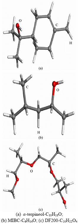
Figure 1 Molecule structures:
DFTB+ module, which is based on the tight-binding method, is used to obtain the initial structures of the interactions between frother molecules and water molecules. For this module, the geometry optimization is built with algorithm of conjugate gradient. Mio (C-H-O-N-S-P) and divide- conquer are selected as the Slater-Koster library and eigensolver, respectively. The convergence criteria for structure optimization are set to 1) energy tolerance of 0.209 kJ/mol, 2) maximum force tolerance of 2.09 kJ/(mol· ), and 3) maximum iterations of 99999999. The smearing is set at 0.005 Ha and all the qualities are under the medium level.
Based on the DFTB+ calculation results, the adsorption of the frother molecule at gas–liquid interface is simulated. The interactions between the polar head group of the frother with different numbers of water molecules are performed by Dmol3 module. In this module, no special treatment of core electrons is considered and all the electrons are included. More specifically, spin-unrestricted is performed and the symmetry is also used. The self-consistent field (SCF) convergence is fixed to 10–6 Ha and the convergence criteria for structure optimization is set to 1) energy tolerance of 1.0×10⁻⁵ Ha, 2) maximum force tolerance of 0.002 Ha/, and 3) maximum displacement tolerance of 0.005 . In particular, regardless of which module we use, the smearing is always set at 0.005 Ha and all kinds of qualities are under the fine level.
To find out how the layer of frother molecules absorbs at the gas-liquid interface, the Forcite module is used in this work. The smart module is selected as the algorithm and the convergence criteria is set to 1) energy tolerance of 8.36×10⁻⁵ kJ/mol, 2) maximum force tolerance of 4.18 J/(mol·), 3) maximum displacement tolerance of 0.005 , 4) maximum iterations of 5000. The forcefield is so critical and cvff_nocross_nomorse is suitable. In addition, group based electrostatic and group based van der Waals are selected in summation method. All the qualities are under the ultra-fine level.
For the reason that the exchange-correlation functional and the basis set are the core parameters in DMol3 module, the dO—H and ∠H—O—H of H2O molecule are calculated under different functionals(all with the DNP+basis set) and the result is shown in Table 1. dO—H here is the distance between atom O and atom H, and ∠H—O—H represents the angle of HOH.
It is clearly shown in Table 1 that the calculated dO—H, ∠H—O—H and hydrogen bond energy of the optimized H2O under the functional of GGA-BP and GGA-VWN-BP are quite close to the experimental values which are tested at 298 K. So in this study, GGA-BP is selected as the exchange- correlation functional.
To find out the optimal basis set, different kinds of basis sets are compared under the functional of GGA-BP and the result is displayed in Table 2.
Table 1 dO—H and ∠H—O—H of H2O molecule under different functional
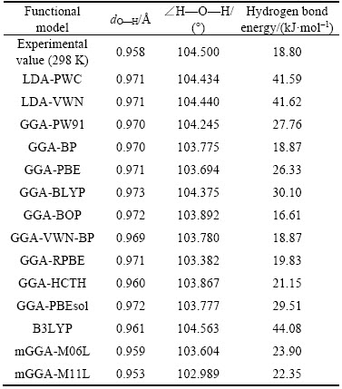
Table 2 dO—H and ∠H—O—H of H2O molecule under different basis sets
Obviously, the result under the basis set of DNP+ is closer to the experimental value as shown in Table 2 and so DNP+ is determined as the best basis set.
The hydrogen bond energy can be calculated by
EH=EH2O—H2O–2EH2O
where EH is the hydrogen bond energy; EH2O–H2O is the total energy of the two water molecules which forms only one hydrogen bond; and EH2O is the energy of one water molecule.
The binding energy can be expressed by the following equation:
△E=Efrother-nH2O–Efrother–nEH2O
where △E is the binding energy; Efrother-nH2O is the total energy of the frother with the water molecules; Efrother is the total energy of the frother molecule; and EH2O is the energy of one water molecule which is calculated under the same condition [10–13].
3 Results and discussion
3.1 Frother molecule in water phase
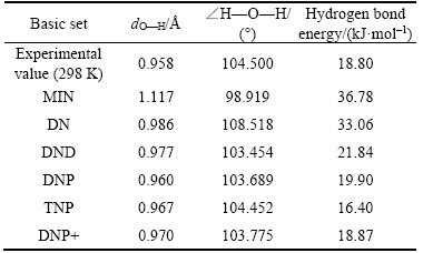
In DFTB+ module, the structures of each frother molecule and water molecule must be optimized first, then the frother molecule should be placed inside the water molecule cluster, leaving the frother molecule just surrounded by water molecules. The result of the interaction between frother molecule and water molecule clusters is shown in Figure 2.
As shown in Figures 2(a)–(c), it is found that the interactions of the three frothers with their surrounding water molecules are not the same. The polar head group in the frother molecule, —OH in α-terpineol, —OH in MIBC, —OH and —O— in DF200, forms hydrogen bonding with water molecules. This suggests that the polar head groups of these three frothers are hydrophilic. Nevertheless, the non-polar head groups (hydrocarbon) in frothers are repelled from water molecules, suggesting the hydrophobic properties of frothers. As a consequence of the hydrogen bonding between the polar head group with water molecule, a hydration shell with a certain structure is formed near the polar head group. Correspondingly, around non-polar group, the water molecules are excluded, forming a space sandwiched between the frother molecule and water molecule cluster.
3.2 Frother molecule adsorbing at gas–liquid interface
The interaction interface between frother molecules and water molecules can be regarded as a gas–liquid interface. In DMol3 module, a frother- nH2O structure is simulated to represent the interaction between one single frother molecule with water molecules. Firstly, one single water molecule is released around the polar head group of the frother molecule, then gradually increases the number of water molecule until the most stable structure is obtained.
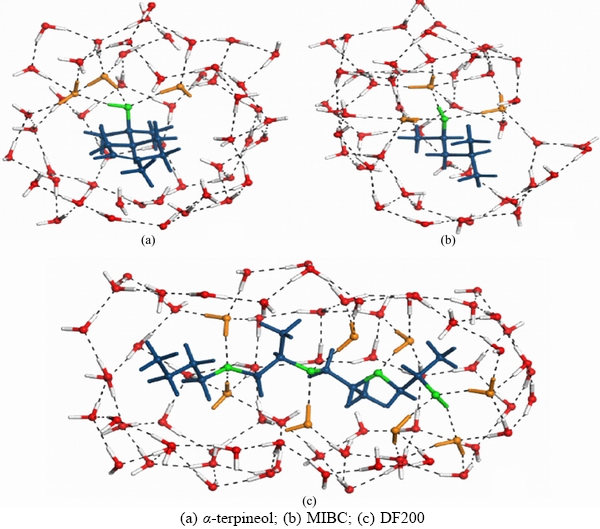
Figure 2 Slices of structures of frother molecules in water phase:(Green: polar head group; blue: non-polar group; orange: water molecule connected directly with the polar head group)
The most stable structure should meet the following conditions. Firstly, the polar head group must be saturated by the hydrogen bonds with water molecules. Secondly, the formed hydration shell structure should neither have excess water molecules, nor lack the necessary water molecules. Sufficient free valence bonds should be left in order to make the polar head group continually connected with the surrounding water molecules. Thirdly, the formed hydration shell structure should also be consistent with the conclusions of the previous section. Lastly, the binding energy should reach the lowest.
3.2.1 α-terpineol
Twenty one kinds of optimized structures of α-terpineol-nH2O are found, as shown in Figure 3 with both the structures and the binding energies (△E). These structures can be classified into three kinds: chain-like structures; ringlike structures and spatial structures. Under the same level of water molecule number, the binding energies (△E) of frother molecule and water molecules vary with the binding structures. It is shown that the △E of spatial structures is the lowest, followed by ring-like structures and then the chain-like structures. This suggests that the spatial structures are the most stable, while the linear structures are the most unstable.
The structural stability of frother-water system is mainly determined by the coordination number of —OH group of frother with water molecules. It is found that three coordinated —OH by water molecules is the most stable, with O coordinated with two water molecules and H coordinated one water molecule, such as the structures IV-4, V-4, V-5, VI-2, VII-2 and VII-3. In addition, the closure degree of water molecules around the —OH group is also very important for the structural stability. For instance, when —OH group is interacted with four water molecules, although structures IV-2, IV-3 and IV-4 have the same coordination number with water molecules, structure IV-4 has the lowest △E due to the completely closed water molecules, followed by structure IV-3 with half closed water molecules and then structure IV-2 with non-closed water molecules. It is also noted that the △E of the dense structures (V-5 and VII-2) are lower than the relatively loose structures, and the —OH group is three coordinated with water molecules and water molecules are fully completed. However, the dense structure can not be regarded as a reasonable structure for its difficulty to be spontaneously formed under natural conditions. Taking all these aspects into consideration, it is convinced that the complex of α-terpineol-7H2O, that is VII-3 in Figure 3, can be selected as the most stable structure that just like a spindle-like structure. The parameters of the structure are displayed in Figure 4.
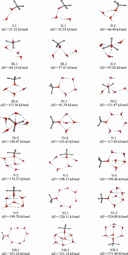
Figure 3 Optimized structures of α-terpineol-nH2O
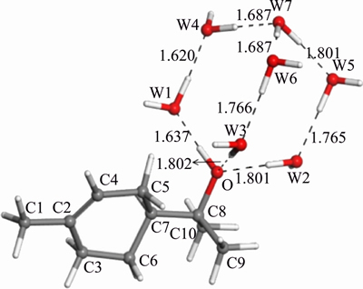
Figure 4 Most stable structure of α-terpineol-7H2O (W: water molecule)
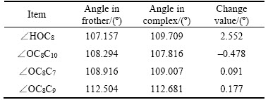
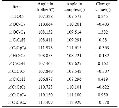
From Figure 4, Tables 3 and 4, the lengths of the hydrogen bonds shown in Figure 4 indicate that the hydrogen bonds belong to moderate-intensity hydrogen bond. The optimized hydration shell changes the polar head group most, while the non-polar group is affected relatively less. The polar head group related dOH, dO—C8, ∠HOC8 change most and without any exception, they are stretched or wider. The changes in bonds and angles reveal the fact that the hydration shell makes the polar head group moves closer to the water phase, while makes the non-polar group repelled by the water phase and closer to the air phase.
Table 3 Changes of bond lengths of α-terpineol-7H2O
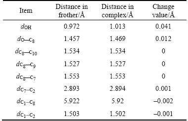
Table 4 Changes of angles of polar head group of α-terpineol-7H2O
There is an interesting point that the ringlike α-terpene structure inside the α-terpineol molecule shows some special properties. The changes of the angle can be seen in Figure 5. This space six- member ring-like structure has an excellent cushioning characteristic. To a certain extent, it can offset hydration shell effect on non-polar group. Specifically speaking, under the influence of the hydration shell, by adjusting the size of some bond angles, this space six-member ring structure is maintained to have its own stability, which makes dC2—C7 barely changed.
3.2.2 MIBC
The research method of MIBC is in line with that of α-terpineol. The results declare that the MIBC with 7H2O structure exhibited in Figure 6 is the most stable structure, which is also the similar spindle-like structure. For the research process, it is so similar with that of α-terpineol in Figure 3, it will not be mentioned here again.
From Tables 5 and 6, it can be concluded that the major changes of the bond length and angle mainly focus on the polar head group, the changes on the non-polar group are less obvious. However, if we compare the two frother together, α-terpineol and MIBC, there are some differences between them. The α-terpineol has a ringlike α-terpene in it while the MIBC is strictly part of the aliphatic alcohol chemical compound. The ringlike α-terpene structure offsets the hydration shell effects on non-polar group that the non-polar group in α-terpineol changes much less than that in MIBC. Specifically speaking, the change is about –0.002 of dC1—C8 in α-terpineol, while respectively 0.018 of dC1—C5 in MIBC. It indicates the stability of the structure of α-terpineol.
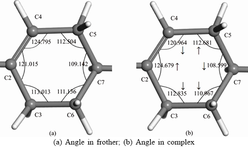
Figure 5 Changes of angles of ringlike α-terpene structure:(Unit: (°); ↑ represents rise; ↓ represents decrease)
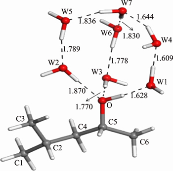
Figure 6 Most stable structure of MIBC-7H2O (W—Water molecule)
3.2.3 DF200
The molecule structure of DF200 is quite different from the above two. It is a one —OH group in the end, three —O— groups distribute within the chain, with long chain branched chain structure. So the research method is quite different. Step 1, for the three —O— groups, two water molecules are placed around each —O— group and there are some different kinds of structures that can be obtained from this step. Among them, the structure with the lowest binding energy is selected. From Sections 3.2.1 and 3.2.2, it can be inferred that the —OH group should combine with the spindle-like hydration shell to form the most stable structure and in fact it is. Then step 2, optimize the selected structure with the spindle-like hydration shell together. The final structure is a DF200- 13H2O structure which is exhibited in Figure 7 in details.
Table 5 Changes of bond lengths of MIBC-7H2O
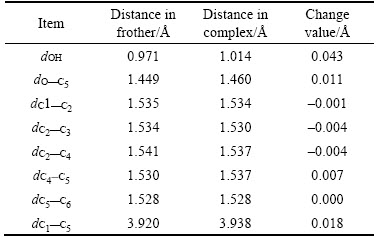
Table 6 Changes of angles of MIBC-7H2O
It can be seen from Figure 7 that there is only one water molecule interacting with O3. This phenomenon is caused by the position of the O3. It can be concluded from here that the interaction between water molecule and polar head group is affected by the position of the non-polar group in chain and the structure of the non-polar group. The two parts are optimized well in Figure 7 and also some hydrogen bonds are built between them. Compared DF200 with the two frothers investigated above, the obviously different point in Figure 7 is that DF200 has much more powerful ability to catch water molecules for the extra three —O— groups.
The changes in bond length and bond angle are basically the similar. From Tables 7 and 8 it can be seen that the polar head group changes more, nevertheless, the non-polar group changes less. There are six more water molecules getting into reaction around the non-polar group, therefore, the non-polar group based bond length and angle alter a little more significant compared with that in α-terpineol and MIBC. The more water molecules get into reaction, the more changes occur on the chain. The dC1—C9 varies obviously from 6.277 to 6.607 , getting a growth of 0.33 , which can be attributed to the increase of water molecules.
The partial density of states(PDOS) of O atoms before and after H2O adsorption is investigated to give insight into the abilities of these three frother molecules bonding with water molecules. Figure 8 shows that the changes of PDOS are mainly concentrated in the range between –7.5 eV and 0 eV. The PDOS of O 2s orbital is at a significantly low level compared with the PDOS of O 2p orbital. More specifically, the O 2s orbital changes less, while the 2p orbital changes more. As far as the changes of PDOS before and after H2O adsorption, for α-terpineol, the PDOS of O 2p orbital in the range between –7.5 eV and 0 eV becomes more localized. For DF200, the PDOS of O1 2p orbital turns more delocalized. For MIBC, the PDOS of O 2p orbital is barely changed. The changes of PDOS indicate that among these three frother molecules, the bonding ability of DF200 is the best, followed by α-terpineol and MIBC. In the meanwhile, there are three —O— in DF200(O2, O3,O4) and the PDOS of these three O atoms before and after H2O adsorption is displayed in Figure 9. It is found that the PDOS of O2 2p orbital and O4 2p orbital are obviously changed, while the PDOS of O3 2p orbital changes slightly [17].
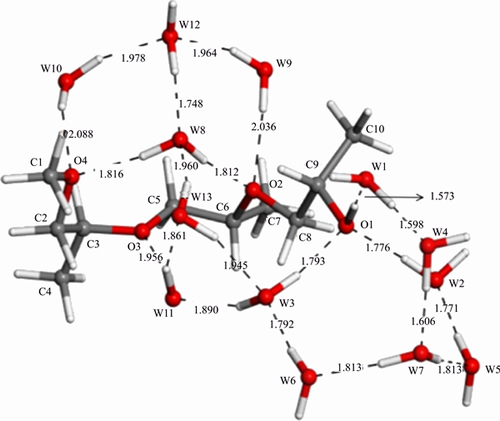
Figure 7 Most stable structure of DF200-13H2O (W—Water molecule)
Table 7 Changes of bond lengths of DF200-13H2O
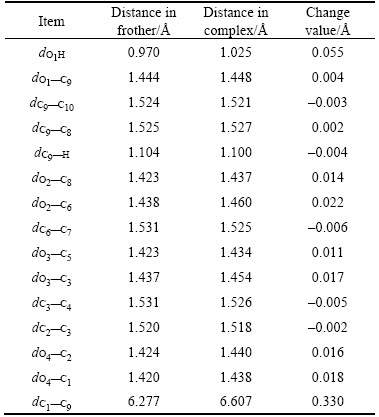
Table 8 Changes of angles of DF200-13H2O
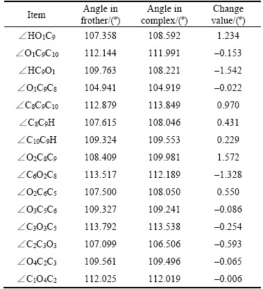
Figure 8 PDOS of O atom in frother molecule before and after H2O adsorption:
3.3 Frothers adsorption layer at gas–liquid interface
Firstly, a 90 ×20 ×10 , density of 1 g/cm3 layer of water molecules with 750 water molecules is built and the layer itself can be regarded as the so-called liquid film. Then, a thickness of 20 vacuum layer is placed onto the surface of liquid film and finally a 90 ×20 ×30 crystal is obtained. The layer of vacuum and the layer of water molecules constitute the two sides of the gas–liquid interface. In this process, the function of amorphous cell is used. Secondly, a layer containing 32 frother molecules is placed above the liquid film within the layer of vacuum and making the polar head group of the frother molecule contacted the surface of the liquid film as closer as possible. It is not until the position of the layer of frother molecules has been finely adjusted that the geometry optimization can be started. The research findings are respectively shown in Figure 10.
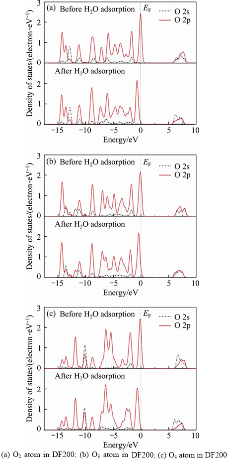
Figure 9 PDOS of O atom in DF200 before and after H2O adsorption:
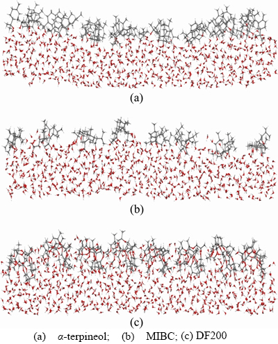
Figure 10 Layer of frother molecules adsorbing at gas–liquid interface:
The disintegration of the foam is mainly affected by two aspects: liquid film drainage effect and the diffusion of gas through the liquid film. The surface viscosity directly determines the speed of the liquid film drainage and it is mainly determined by the interaction between hydrophilic group (that is the polar head group in frother molecule) and water molecules. The higher the surface viscosity is, the lower the liquid film drainage rate will be. And the decrease of the liquid film drainage rate will make the foam more stable. Respectively, the structure of the frother molecule and the arrangement of the frother molecules on liquid film have an impact on the strength of the diffusion effect [18, 19].
As far as the liquid film drainage effect, the single α-terpineol molecule and MIBC molecule are similar in structure for they both contain just one —OH group. So the binding ability of these two is nearly the same (both bind with 7H2O to form the stable complex, see Sections 3.2.1 and 3.2.2). On the contrary, there are three —O— groups as the hydrophilic (polar head) groups in the DF200 molecule, especially they are distributed within the chain and not in one end. Generally speaking, the hydrophilic ability of the hydrophilic group which exists in the middle of the molecule (as —O— group in DF200) is stronger than that at the end (as —OH group in DF200). Additionally, from Section 3.2.3, it can be seen that there is 13H2O binding with one DF200 molecule to compose the stable structure. The number of the water molecules connected with the frother molecule can represent the surface viscosity. So in summary, among the three frothers, the surface viscosity of the liquid film of the DF200 is the strongest, while the α-terpineol and MIBC are almost at the same level. That is also to say, the liquid film drainage rate of DF200 is the lowest, while α-terpineol and MIBC are almost the same [18, 20].
In terms of the diffusion of gas through the liquid film: for the structure of the frother molecule, the hydrophobic group (that is the non-polar group in frother molecule) decided the diffusion velocity. The greater the hydrophobic group is, the smaller the diffusion velocity will be, and thus the stability of the foam will get much greater. The hydrophobic group(non-polar group) of MIBC is the smallest among the three, and the hydrophobic group is greater in α-terpineol than that in DF200. Although their hydrophobic groups both have 10 carbon atoms, the hydrophobic group in α-terpineol is one kind of complex structure which contains a space six-member ring like structure, while the hydrophobic group in DF200 is just a simple single chain structure. Hence, under the hydrophobic group level, the diffusion velocity of α-terpineol is the lowest and the velocity of DF200 is lower than α-terpineol. For the arrangement of the frother on liquid film, as demonstrated in Figure 10, the α-terpineol molecules are more neatly arranged and greater distributed which make the frother interface thicker on the thickness and higher on the intensity. All of these characteristics show that the layer of α-terpineol molecules blocks the diffusion of gas through the liquid film better than MIBC and DF200. As for DF200 and MIBC, it is obvious that MIBC is arranged much more loosely than DF200. For the stronger ability of binding with more water molecules, DF200 molecules are more deeply inset into the liquid film. So DF200 is more capable of blocking the gas diffuse through the liquid film than MIBC in terms of the arrangement on liquid film [18, 21].
The structure of α-terpineol molecule has a great impact on its foam stability. DF200 and MIBC are both liner chain structures. However, α-terpineol has a six-member ring structure with a carbon- carbon double bond, which can lower the flexibility of the generated bubble wall compared with liner chain structure. In addition, the branched structure on the ring can reduce its polarity, making the structure being certainly curved and consequently the ring structures being closely ranked, which can strengthen the stability of foam [18, 20–22].
Based on the discussion above, it can be concluded that the foam stability of α-terpineol is the best, followed by DF200 and MIBC, which are consistent with the experimental results[18, 19].
4 Conclusions
1) The adsorption of α-terpineol, MIBC, DF200 frothers at the gas–liquid interface is investigated by DFT simulations and MD method. The adsorption of frother at the gas–liquid interface is related to the structure of the polar head group and the non-polar group of frother molecule. Both α-terpineol molecule and MIBC molecule, which have a single —OH group, have almost the same spindle-like structure of hydration shell. The DF200 molecule includes a single —OH group and three —O— groups, resulting in the hydration shell containing more water molecules. It is found that the liquid film drainage rate of DF200 is the lowest, while α-terpineol and MIBC are almost the same.
2) Forcite simulation results suggest that because of the ringlike structure, the α-terpineol molecules are more neatly arranged and better distributed, which makes the frother interface thicker and higher intensity. It is obvious that MIBC is arranged much more loosely than DF200. However, for the stronger ability of binding with water molecules, DF200 molecules are more deeply inset into the liquid film than MIBC. These results suggest that at the gas–liquid interface, the diffusion performance of MIBC is the best, while α-terpineol is the worst. This can be ascribed to the structure of the different non-polar group in frother molecule.
3) Based on the above results, in terms of foam stability, it is revealed that α-terpineol is the best, followed by DF200 and MIBC.
References
[1] TAN Y H, FINCH J A. Frother structure-property relationship: Aliphatic alcohols and bubblerise velocity [J]. Minerals Engineering, 2016, 96–97: 33–38. DOI: 10.1016/ j.mineng.2016.05.014.
[2] KRACHTA W, HUNT C. Indirect measurement of frother concentration based on l-CCC curves [J]. Minerals Engineering, 2016, 92: 110–113. DOI: 10.1016/j.mineng. 2016.03.010.
[3] KOWALCZUK P B, MROCZKO D, DRZYMALA J. Influence of frother type and dose on collectorless flotation of copper-bearing shale in a flotation column [J]. Physicochemical Problems of Mineral Processing, 2015, 51(2): 547-558. DOI: 10.5277/ppmp150215.
[4] PHAN C M, NAKAHARA H, SHIBATA O, MOROI Y, NGUYEN C V, CHAUDHARY D. Surface potential of MIBC at air/water interface: A molecular dynamics study [J]. e-Journal of Surface Science and Nanotechnology, 2012, 10: 437–440. DOI: 10.1380/ejssnt.2012.437.
[5] XINGA Y W, GUID X H, CAOB Y J, WANGA Y W, XUA M D, WANGA D Y, LIA C W. Effect of compound collector and blending frother on froth stability and flotation performance of oxidized coal [J]. Powder Technology, 2017, 305: 166–173. DOI: 10.1016/j.powtec.2016.10.003.
[6] YIANATOSA J, VINNETTA L, CARRASCOA C, ALVAREZ-SILVAA M. Effect of entrainment in bubble load measurement on froth recovery estimation at industrial scale [J]. Minerals Engineering, 2015, 72: 31–35. DOI: 10.1016/j.mineng.2014.12.017.
[7] RAMOS O, CASTRO S, LASKOWSKI J S. Copper- molybdenum ores flotation in sea water: Floatability and frothability [J]. Minerals Engineering, 2013, 53: 108–112. DOI: 10.1016/j.mineng.2013.07.009.
[8] PARK H, WANG Jun-yu, WANG Li-guang. A comparative study of methyl cyclohexanemethanol and methyl isobutyl carbinol as frother for coal flotation [J]. International Journal of Mineral Processing, 2016, 10: 32–44. DOI: 10.1016/ j.minpro.2016.08.006.
[9] WANG Dian-zuo. Flotation reagents: Applied surface chemistry on minerals flotation and energy resources beneficiation [M]. Singapore: Springer,2016.
[10] CHEN Jian-hua, LAN Li-hong, CHEN Ye. Computational simulation of adsorption and thermodynamic study of xanthate, dithiophosphate and dithiocarbamate on galena and pyrite surfaces [J]. Minerals Engineering, 2013, 46-47: 136-143. DOI: 10.1016/j.mineng.2013.03.015.
[11] LI Yu-qiong, CHEN, Jian-hua, LAN Li-hong, GUO Jin. Adsorption of O2 on pyrite and galena surfaces [J]. The Chinese Journal of Nonferrous Metals, 2012, 22(4): 1184-1193. (in Chinese)
[12] ZHAO Cui-hua, CHEN Jian-hua, LONG Xian-hao, GUO Jin. Study of H2O adsorption on sulfides surfaces and thermokinetic analysis [J]. Journal of Industrial & Engineering Chemistry, 2014, 20(2): 605-609. DOI: 10.1016/ j.jiec.2013.05.021.
[13] CHEN Jian-hua, LONG Xian-hao, CHEN Ye. Comparison of multilayer water adsorption on the hydrophobic galena (PbS) and hydrophilic pyrite (FeS2) surfaces: A DFT study [J]. Journal of Physical Chemistry C, 2014, 118(22): 11657–11665. DOI: 10.1021/jp5000478.
[14] CHEN Mei-ling, WANG Zheng-wu, WANG Hai-jun, ZHANG Ge-xin, TAO Fu-ming. Investigation of adsorption of surfactant at the gas-liquid interface with quantum chemistry method [J]. Chinese Science Bulletin, 2007, 52(11): 1451–1455. (in Chinese)
[15] TUMA C, BOESE A D, HANDY C N. Predicting the binding energies of H-bonded complexes: A comparative DFT study [J]. Physical Chemistry Chemical Physics, 1999, 1(17): 3939–3947. DOI: 10.1039/A904357H.
[16] SHISHKIN O V, GORB L, LESZCZYBSKI J. Does the hydrated cytosine molecule retain the canonical structure? A DFT study [J]. Journal Physical Chemistry B, 2000, 104(22): 5357–5361. DOI: 10.1021/jp993144c.
[17] HUANG De-wei, ZHAO Cui-hua, CHEN Jian-hua, LI Yu-qiong, LI Wei-zhou. First-principle study of electronic structure and optical properties of Au-doped VO2 [J]. Journal of Central South University, 2017, 24(2): 270-275. DOI: 10.1007/s11771-017-3427-7.
[18] CHEN Yang. Measurement techniques of foam performance and influence factors of foam stability [J]. China Ming Magazine, 2014, 23(S2): 230–233. (in Chinese)
[19] DEVRIES A J. A fundamental investigation of the factors controlling the stability of foams [J]. Rubber Chemistry and Technology, 1958, 31(5): 1142–1205. DOI: 10.5254/1.3542363.
[20] ZHAO Long-mei. The foaming properties of common frother [J]. Sciencepaper Online, 2010, 5(6): 419–422. (in Chinese)
[21] DENG Li-jun. Effect of surface tension on bubble size in frother solutions [J]. China Science Paper, 2012, 9(12): 1340–1343. (in Chinese)
[22] GU Yan-ling. A new method of testing frother performance [J]. Transactions of Nonferrous Metals Society of China, 2013, 23(9): 2776–2780. DOI: 10.1016/S1003-6326(13) 62796-X.
(Edited by FANG Jing-hua)
中文导读
起泡剂在气液界面的吸附结构的DFT研究
摘要:采用密度泛函理论(DFT)模拟研究了起泡剂与气泡气液界面之间的吸附机理。在水相中,起泡剂分子的极性基团通过氢键与水分子连接,而非极性基团表现出疏水性并且排斥开其周围的水分子。水分子在单一起泡分子上的吸附现象表明,α-萜烯醇与7个水分子,MIBC与7个水分子,DF200与13个水分子的配合物分别达到了他们的稳定结构。水化层同时影响极性基团和非极性基团。DF200的液膜排液速率最慢,而α-萜烯醇和MIBC几乎相同。吸附在气–液界面处的起泡剂分子的吸附层显示α-萜烯醇分子排列整齐、分布更好,而DF200分子的排列比MIBC分子更加松散,这表明,与DF200和MIBC相比,α-萜烯醇分子层可以更好地阻止气体通过液膜扩散。模拟结果表明,α-松油醇的泡沫稳定性最好,其次是DF200和MIBC。
关键词:起泡剂;水相;气液界面;起泡性能;密度泛函理论
Foundation item: Projects(51574092, 51874106) supported by the National Natural Science Foundation, China; Project supported by Special Program for Applied Research on Super Computation of the NSFC-Guangdong Joint Fund(the second phase), China
Received date: 2017-03-26; Accepted date: 2018-10-26
Corresponding author: CHEN Jian-hua, PhD, Professor; Tel: +86-771-3232200; E-mail: jhchen@gxu.edu.cn; ORCID: 0000-0002-0254- 0655

