
Effect of sodium modification on microstructure and mechanical properties of thick-walled AlSi6Cu2.5 rheocast component
M. WESS?N, N. E. ANDERSSON, O. GRANATH
School of Engineering, Materials and Manufacturing-Casting, J?nk?ping University,
PO Box 1026, SE-551 11 J?nk?ping, Sweden
Received 13 May 2010; accepted 25 June 2010
Abstract: The microstructure and tensile properties were investigated in a thick-walled section (approximately 45 mm×43 mm) of a rheocast component produced by the RheoMetalTM process. Due to the long solidification period of such components, it is expected that the Al-Si eutectic formed will be coarse. Therefore, sodium (Na) was used as a modifying agent to reduce the coarseness of the eutectic. Tensile test bars were machined from three different sets of materials: 1) non-modified melt, 2) modified melt cast directly after Na addition, and 3) modified melt cast 30 min after Na addition. The alloy used was a secondary AlSi6Cu2.5 alloy (STENAL Rheo1), specially developed for rheocasting. The material was studied in the as-cast condition as well as after a T6 heat treatment. The results show that the Al-Si eutectic is significantly refined by the Na addition, even after a fading time of 30 min. However, it is observed that the Na modification generally has a detrimental effect on the mechanical properties, despite the structure refinement. This is especially true in the T6 heat treated condition, where the yield strength is reduced by more than 30%. Some possible mechanisms for the degradation of mechanical performance are discussed.
Key words: rheocasting; thick-walled component; eutectic modification; mechanical properties; sodium; Al alloys
1 Introduction
Semi-solid casting is characterised by the use of a partially solidified metal alloy having a globular microstructure, also known as slurry, to produce thick-walled or thin-walled cast components. Semi-solid casting is divided into two main routes: thixocasting and rheocasting. Thixocasting is the forming of components from reheated billets in the semi-solid state. Rheocasting is the production of semi-solid slurry from a melt normally followed by component casting in a high pressure die casting (HPDC) machine. The semi-solid route considered in this work is rheocasting, and slurry production has been done using a RheoMetalTM slurry station. The RheoMetalTM process is based on the rapid slurry forming (RSF) technology. This process involves an enthalpy exchange between two alloy systems where one alloy is the superheated melt and the other is the cold solid enthalpy exchange material (EEM) alloy piece, which is immersed and stirred in the melt. During stirring, melting and dissolution of the EEM occur quickly, thereby forming metal slurry. As a consequence, a new alloy system will form with a certain enthalpy and solid fraction. More in depth description of the RSF technology has been presented elsewhere[1-2]. The influence of slurry process parameters in the RheoMetalTM process has previously been investigated for aluminium alloys[3]. One of the advantages of using the RheoMetal TM process is that it is possible to produce thick-walled cast components, which are virtually free from porosity, using standard cold chamber HPDC machines. This means that components with pressure tightness requirements, which typically have been produced by gravity casting or even by machining from a blank, now can be produced at a lower cost via rheocasting. To achieve low porosity it is important to have a correct component design and ingate design. Some other rheocasting processes used to varying extent for producing aluminium slurries are new rheocasting (NRC), semi-solid rheocasting (SSR), sub liquidus casting (SLC), continuous rheoconversion process (CRP), swirled enthalpy equilibrium device (SEED) and Honda advanced semi-solid casting technology[4-9].
The most common alloys for semi-solid casting are A356 or A357. These alloys have been reported to generate good mechanical properties in rheocast components[10]. A new secondary unmodified alloy based on an AlSi6Cu2.5 composition has been developed in an effort to decrease the alloy cost in semi-solid casting towards the standard HPDC A380 alloy without severely reducing castability or mechanical properties[11]. This new alloy (STENAL Rheo1) is similar to A319, which has previously been investigated in thixocasting[12].
The effect of chemical eutectic modification by strontium or sodium in aluminium alloy castings is well known. It has also been claimed that mechanical stirring, such as electromagnetic stirring, has an effect on modification of silicon particles in rheocasting[13]. A major advantage of semi-solid casting is the possibility to cast thick-walled components with reduced porosity level, thus not lowering the mechanical properties by such defects. The aim of this work is to investigate the effect of chemical modification by sodium on microstructures and mechanical properties of thick-walled rheocast components using a secondary AlSi6Cu2.5 alloy.
2 Experimental
In this study, components were produced in open atmosphere rheocasting trials using a RheoMetalTM slurry station. In step 1 of the casting trials, an unmodified AlSi6Cu2.5 alloy was used. The chemical composition of this alloy, measured in the gating system of cast components, is shown in Table 1. In step 2 of the casting trials, the alloy was modified with sodium using Foseco SIMODAL-77 tablets. After this casting trial, the melt was held for 30 min before a third casting trial was made. These two trials will be referred to as “Na, 0 min” and “Na, 30 min” respectively, and their respective chemical composition, measured in the gating system of cast components, are also shown in Table 1.
Table 1 Chemical compositions of AlSi6Cu2.5 alloy unmodified (base) and modified with Na at various fading times (0 min and 30 min) (mass fraction, %)

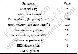
The rheocasting trial was done using a cold chamber HPDC machine having a 750 t locking force. A RheoMetalTM slurry station was connected to the HPDC machine together with an automatic robot dosing unit. Shot mass, casting machine parameters and slurry machine parameters were set according to the parameter layout in Table 2. After correct melt dosing and ladle transfer to the slurry station by the robot dosing unit, the EEM, with its height dimensioned for the EEM to be approximately 4% (mass fraction) of the melt mass, was immersed and stirred into the melt during 30 s for slurry production. After its formation, the slurry was automatically poured from the ladle into the shot sleeve of the HPDC machine for injection into the die cavity.
Table 2 Shot mass, casting machine parameters and slurry machine parameters
All components were cast with a gating system modified according to rheocasting principles. After casting, the gating systems were separated from the components for sample evaluation purposes. The height and width of the gating where the samples were taken was approximately 45 mm and 43 mm, respectively, giving a cross section area of 1 765 mm2, as illustrated in Fig.1. Samples for microscopy investigation were taken from the centre of the cross section. The surface of the hardness test samples was ground flat before testing. Normal metallographic procedures for aluminium alloys were followed during microscopy sample preparation and polishing. Microstructures were studied using a Leica DMRX optical microscope as well as a JEOL 7001F FEGSEM. Seven tensile test specimens were taken from the gating, as shown in Fig.1. The dimensions of these specimens are shown in Fig.2. The crosshead velocity of the tensile test machine was 1 mm/min, applying an increasing load until the specimen fractured. A double-sided clip-on type extensometer with gauge length of 20 mm was used. Six of the specimens were used for tensile testing, and one specimen was saved for reference purposes.
The tensile test bars were evaluated both in the as-cast state and in a T6 heat treated state. The following heat treatment cycle was applied: solution heat treatment at 490 °C for 6 h, quenching in water, and artificial aging at 170 °C for 10 h. The Brinell hardness was measured using a 5 mm ball and a load of 612.5 N.

Fig.1 Dimensions of gating system, also showing locations for taking tensile test bars
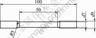
Fig.2 Dimensions of tensile test specimen (Unit: mm)
3 Results and discussion
For good rheocasting characteristics, it is desirable to use alloys with a large amount of primary α(Al) phase, hence relatively low Si-contents. However, at a too low Si-content, problems related to hot tearing can be expected. The calculated solid fraction of the alloy used in this trial, using Thermo-Calc[14] together with the TTAL database[15], is shown in Fig.3. It is found that the amount of primary α(Al) phase formed is between 54% and 58% assuming Scheil segregation and full equilibrium. This is slightly higher as compared with the more commonly used A356 and A357 alloys, where the amount of primary α(Al) phase is around 50%. A simple thermal analysis of the non-modified melt was done by measuring the temperature in the centre of a graphite cup (d50 mm) during solidification. The recorded cooling curve is shown in Fig.4. It is seen that temperatures for onset of the α(Al) phase (labelled FFC_A1 in Fig.3), as well as for the Si-eutectic, correspond rather well with the Thermo-Calc predictions. However, the thermal analysis reveals that the precipitation of the Cu-rich phases Al7Cu2Fe and Al2Cu starts at around 505 °C and 500 °C, respectively, which is 15-20 °C lower than the Thermo-Calc predictions assuming Scheil segregation. The discrepancy can most likely be explained by nucleation characteristics which naturally are not accounted for in the equilibrium calculations.
The microstructures evaluated in the centre of the cross section for the three different materials produced, i.e. non-modified, Na, 0 min, and Na, 30 min, are shown in Figs.5(a)-(c). Naturally, the microstructure consists of predominantly globular α(Al) grains surrounded by the α(Al)/Si eutectic (most easily seen in the Na modified samples). Additionally, a small amount of massive intermetallic phases exist.

Fig.3 Scheil segregation (solid line) and equilibrium (dotted line) computed by ThermoCalc[14] using TTAL database[15] (original AlSi6Cu2.5 composition from Table 1 used)
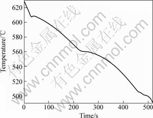
Fig.4 Cooling curve measured during solidification in d50 mm sampling cup using non-modified AlSi6Cu2.5 alloy
It is clear that the Na modification has led to a significant refinement of the eutectic as expected, by comparing Fig.5(a) with Figs.5(b) and (c). In the modified samples, it is difficult to distinguish the individual Si lamellae using light optical microscopy, while the Si lamellae have a length up to approximately 100 μm in the non-modified sample. Interestingly, the coarseness of the α(Al)/Si eutectic does not change to any major extent even after a fading time of 30 min, even though the Na content has decreased from 4.3×10⁻⁵ to 3×10⁻⁵ (see Table 1). This means that even a very small amount of sodium provides a proper modification effect on the α(Al)/Si eutectic.
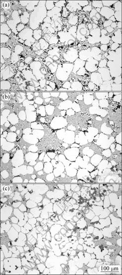
Fig.5 Microstructures obtained in various materials produced: (a) AlSi6Cu2.5; (b) Na, 0 min; (c) Na, 30 min
By using a SEM supplied with a EDS detector, the chemical composition of the intermetallic phases was analyzed. In Fig.6, the appearance of the phases Al2Cu and Al15(Fe,Mn)3Si2 (denominated “ALPHA” in Fig.3) are shown.
The hardness values evaluated in the centre as well as close to the surface are shown in Table 3. The most striking feature of these measurements is that the hardness is lower in the Na modified samples. The hardness on the surface as well as in the centre has decreased by almost 10 % directly after Na modification. There is no major change in hardness of the modified samples after a fading time of 30 min. Generally, a fine microstructure is expected to have a higher hardness than a coarse one. However, the measurements in this experimental series indicate the contrary result. Some possible mechanisms which could lead to such an abnormal behaviour are discussed below.
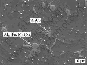
Fig.6 SEM image indicating appearance of major intermetallic phases existing in microstructure
Table 3 Brinell hardness including standard deviations obtained in each component

1) It is generally accepted that the modification effect of the α(Al)/Si eutectic is obtained by a reduced growth velocity, thereby decreasing the growth temperature. The growth velocity, v, and microstructure coarseness, λ, can be related to each other using the following equation[16]:
v?λ2=C (1)
where C is a constant.
A consequence of a lower growth temperature is that the α(Al) phase is given more time to grow before being interrupted by the eutectic growth, thus leading to a higher primary α(Al) phase content. The hardness of the eutectic is higher than that of the α(Al), which consequently will give the result that a modified melt could lead to a microstructure with a lower hardness than a non-modified one. An attempt was made to quantify the amount of primary α(Al) phase in the samples, but due to the very coarse eutectic structure in the non-modified samples, it is impossible to distinguish between primary and eutectic α(Al) phase in this microstructure, and no reliable results are obtained.
2) Elements added in small amounts can have a very strong effect on the phase morphology during eutectic growth, in addition to the coarseness. This is typically the case in cast irons where the existence of minute amounts of trace elements such as lead can give rise to “spiky” graphite or other degenerated graphite morphologies[17]. The elements act either by directly changing the conditions at the phase boundary, thereby affecting the growth morphology, or by indirectly eliminating other surface active elements. This is probably the mechanism by which added Mg alters the S and O contents in cast irons, thereby controlling the transition from lamellar graphite to compacted graphite and then to nodular graphite. Thus, these elements affect the phase interfaces, and it is then also possible that the cohesion between the phases is affected negatively. Consequently, the addition of Na to Al-Si alloys might lead to weaker contact between the Si-phase and the α(Al) phase, which will lead to a lower hardness. It is, however, beyond the scope of this experimental work to investigate this in more detail.
3) When the Na addition is made, it is observed that the melt surface is oxidized more than that before the addition, and also obtains a slight blue colour. As a natural consequence, more oxides might have ended up in the final castings. Normally, it is not expected that the hardness should be significantly affected by small amounts of oxides incorporated into the microstructure. Instead, such defects will mainly control the elongation at fracture. However, it cannot be excluded that the hardness might be reduced if the oxide content is increased.
The results from the tensile tests of the non heat treated samples are shown in Table 4, and complete stress-strain curves from material version (the sample having the highest fracture elongation) are plotted in Fig.7.
Obviously, the yield strength also has decreased by almost 10% in the Na modified samples as compared with the non-modified ones. The ultimate tensile strength is not significantly affected by the Na modification, even though the samples cast 30 min after the modification treatment show somewhat lower values. The elongation values have increased after Na modification. Further, it is interesting to note that the standard deviation values generally are lower in the Na modified samples. This positive effect is most likely related to the significant refinement of the Al-Si eutectic caused by the Na modification. The standard deviation and the elongation values are both strongly connected to the defect (oxide) content.
Table 4 Tensile properties including standard deviations obtained in as-cast condition


Fig.7 Stress-strain curves obtained for various materials in as-cast state as well as in T6 heat treated state
The strength has been strongly increased by the T6 treatment, as seen in Table 5. The corresponding stress―strain curves (the samples having the highest fracture elongation) are also shown in Fig.7. The most obvious feature is that the Na modified samples now have significantly larger standard deviation for the yield strength as well as the tensile strength. Further, the strength level is strongly reduced by the Na modification; even the yield strength has been reduced by more than 30% when comparing the non-modified samples with the modified ones cast after 30 min. There is no major difference in fracture elongation between different materials.
Table 5 Tensile properties including standard deviations obtained after T6 heat treatment

During tensile testing, it is observed that the stress level increases discontinuously for the Na modified samples, thus giving rise to a jagged stress-strain curve. Typically, this behaviour starts after a strain of approximately 2%. The effect is the strongest for the T6 heat treated samples cast directly after Na modification, as can be seen when comparing the curves in Fig.7. It is beyond the scope of this investigation to make an in-depth analysis of this phenomenon. However, it is assumed that it can be related to crack growth characteristics and decohesion between phases within the Al-Si eutectic.
Some representative SEM images of fracture surfaces obtained in the unmodified sample as well as in the “Na, 0 min” sample in the T6 state are shown in Fig.8. In contrast to the observation about the melt surface oxidation during Na addition, as previously mentioned, no obvious difference in the fracture surfaces appearance with respect to oxides can be found.
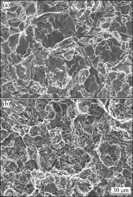
Fig.8 Typical fracture surface morphologies of unmodified (a), and Na, 0 min (b) samples
4 Conclusions
1) There is a significant refinement of the Al-Si eutectic by the Na addition. The effect is preserved even after a fading time of 30 min in the holding furnace.
2) Generally, there is a degradation of the mechanical properties after the Na modification treatment. The mechanical properties are further degraded after a fading time of 30 min in the holding furnace. This is valid both in the as-cast state as well as in the T6 heat treated state.
3) Consequently, the authors do not recommend the use of Na as a modifying agent for thick-walled rheocast components.
References
[1] WESS?N M, CAO H. The RSF technology: A possible breakthrough for semi-solid casting processes [C]//Proc 3rd Int Conf on High Tech Die Casting, AIM. Vicenza, Italy, 2006.
[2] GRANATH O. Semi-solid casting of aluminium and magnesium alloys [R]. Department of Materials and Manufacturing Technology, Research Series from Chalmers University of Technology. Report No. 24, 2007.
[3] GRANATH O, WESS?N M, CAO H. Determining the effect of slurry process parameters on semisolid A356 alloy microstructures produced by the RheoMetalTM process [J]. Int J of Cast Met Res, 2008, 21(5): 349-356.
[4] KAUFMANN H, WABUSSEG H, UGGOWIZER P J. Metallurgical and processing aspects of the NRC semi-solid casting technology [J]. Aluminium, 2000, 76 (1/2): 70-75.
[5] MARTINEZ R A, FLEMINGS M C. Evolution of particle morphology in semi-solid processing [J]. Metall Mater Trans A, 2005, 36: 2205-2210.
[6] JORSTAD J, THIEMAN M, KAMM R, LOUGHMAN M, WOELKE T. Sub liquidus casting (SLC): Process concept and product properties [C]//AFS Transactions and the 107th Annual Castings Cong. Milwaukee, USA, 2003: 399-405.
[7] PAN Q Y, APELIAN D, HOGAN P. The continuous rheoconversion processTM: Optimization 6c industrial applications [J]. Metallurgical Science and Technology, 2006, 24(2): 9-18.
[8] DOUTRE D, HAY G, WALES P, GABATHULER J P. SEED: A new process for semi-solid forming [C]//Proc 42nd Annual Conf of Metallurgists of CIM, Int Symposium on Light Metals. Vancouver, Canada, 2003: 293-306.
[9] YAMAZAKI M, TAKAI A, MURAKAMI O, KAWABATA M, TANIKAWA H, ITO O, KUROKI K. Development of a high-strength aluminium cylinder block for diesel engine employing a new production process [C]//SAE World Congress. Detroit, USA, 2004, 2004-01-1447.
[10] BASNER T, EVANS M. Rheocasting of semi-solid A357 aluminium [C]//SAE World Congress. Detroit, USA, 2000, 2000-01-0059.
[11] STENA Aluminum AB. http://website: www.stenametall.com [EB/OL]. 2010-08-27
[12] BERGSMA S C, LI X, KASSNER M E. Semi-solid thermal transformations in Al-Si alloys. Ⅱ: The optimized tensile and fatigue properties of semi-solid 357 and modified 319 aluminum alloys [J]. Mater Sci Eng A, 2001, 297(1/2): 69-77.
[13] NAFISI S H, GHOMASHCHI R, EMADI D, SHEHATA M T. Effect of stirring on the silicon morphological evolution in hypoeutectic Al-Si alloys [J]. TMS Light Metals, 2005: 1111-1116.
[14] SUNDMAN B, JANSSON B, ANDERSSON J O. The thermo-calc databank system [J]. Calphad, 1985, 9: 153-190.
[15] SAUNDERS N J. The application of calculated phase equilibria to multi-component aluminium alloys [J]. Japanese Inst Light Metals, 2001, 51(3): 141-150.
[16] KURTZ W, FISHER D J. Fundamentals of solidification [M]. Switzerland: Trans Tech Publications, 1984: 208.
[17] KANNO T. Abnormal graphite in spheroidal graphite cast iron [J]. Journal of Japan Foundry Engineering, 2004, 76(2): 130-134.
(Edited by YANG Bing)
Corresponding author: M.WESS?N; Tel: +4636-101666; E-mail: Magnus.Wessen@jth.hj.se
DOI: 10.1016/S1003-6326(09)60352-6

