
Microstructure and deposition mechanism of
electrodeposited Cu/liquid microcapsule composite
XU Xiu-qing, ZHU Li-qun, LI Wei-ping, LIU Hui-cong
School of Materials Science and Engineering, Beihang University, Beijing 100191, China
Received 8 October 2010; accepted 2 April 2011
Abstract: The nanostructured copper/microcapsule containing liquid core materials composite (copper/liquid microcapsules composite) was prepared using direct current (DC) electrodeposition method. The surface morphology and microstructure of composite were investigated by means of scanning electron microscopy (SEM), transmission electron microscopy (TEM) and X-ray diffraction (XRD). The results show that the microstructure of electrodeposited layer transformed from bulk crystal to nano structure because of the participation of microcapsules. The diameters of microcapsules and the copper grain sizes in the composite were 2-20 ��m and 10-20 nm, respectively. In addition, the electrodeposition mechanism of composite in the deposition process followed electrochemistry theory, which was proved by the theoretical analysis result and the experiment results. Meanwhile, the co-deposition process model was presented.
Key words: copper/liquid microcapsule composite; DC electrodeposition; nanostructure; electrodeposition mechanism
1 Introduction
Nowadays, composite coatings have been widely used in auto and aerospace industries due to their special physical, chemical, biological and mechanical properties, etc [1-3]. Especially, nanostructured composites have attracted more and more attention in recent years. Numerous research evidences show that nanostructured coatings possess better physical and mechanical performance than conventional coarse-grained coatings [4-5]. One way to obtain nanostructure during plating is using pulse reverse current [6] by controlling the magnitude of current and pulse width; another is adding nano particles [7-9]. At present, nanostructured composites such as Ni/ZrO2, Ni/SiC, Ni/PZT, Ni/diamond, and Cu/graphite coatings have been successfully produced by pulse current and pulse reverse current electrodeposition. All these nano-composites above are obtained by metal ions co-deposition with solid particles. Compared with solid particles, the metal/liquid microcapsule composites exhibit some distinctive advantages. One of the promising advantages of this composite is that the encapsulated liquid core material can be released gradually to modify the properties of coating surface.
Unfortunately, few investigations on the electrolytic co-deposition of metals and liquid microcapsules have been published. Available researches focus on the preparation process of microcapsules and the performance of composite coating [10-12]. In our previous work [13-15], we had also reported the successful co-deposition of liquid microcapsules with nickel and copper, where excellent wear resistance, corrosion resistance and hydrophobic properties of the composite coating were exhibited. However, it was found that the copper grains became very fine due to the participation of liquid microcapsule during the deposition process. The microstructure of metal/liquid microcapsule composites and their formation mechanism have not been further discussed. Besides, the co-deposition process of microcapsule is quite different from that of solid particles. Guglielmi��s model is used to explain the mechanism of metal/nano solid particles composite. But for the Cu/liquid microcapsule composite, this model seems inappropriate obviously due to the restriction of electronic double layer thickness. Therefore, a new theory is needed to interpret the electrodeposition mechanism of this composite.
In this study, the sizes of liquid microcapsules obtained were in the range of 2-20 ��m and the nanostructured Cu/liquid microcapsule composite was prepared using the direct current electrodeposition method. The effects of microcapsules on microstructure and its formation mechanism of the composite were investigated. Meanwhile, the electrodeposition mechanism of composite containing liquid microcapsules was further analyzed.
2 Experimental
2.1 Materials
The core and shell materials of the microcapsules were BH-102 liquid hydrophobic agent (the main component was described in detail in Ref. [16]) and methyl cellulose (MC, cP 15-25), respectively. Span 80 and anhydrous alcohol acted as dispersant and flocculant in the preparation procedure of liquid microcapsule, respectively.
For the electroplating, the cathode was a low-carbon steel plate (1%, mass fraction): with dimensions of 30 mm��12 mm��0.6 mm and the anode was a phosphorized copper plate. The electrolyte consisted of 200 g/L copper sulfate, 60 g/L sulfuric acid and 60 mg/L hydrochloric acid. The chemicals of analytical reagent grade and distilled water were used to prepare the solution.
2.2 Preparation of copper/liquid microcapsule composite
Firstly, the liquid microcapsule was prepared by means of the phase separation method. The detailed preparation procedure was as follows. 20 mL 0.01 g/mL aqueous MC solution was added to a beaker and stirred at 1 000 r/min at room temperature. Then 1 mL hydrophobic agent was added dropwise to the MC solution. After 5 min, minor Span 80 and 5 mL anhydrous alcohol were added at the speed of 10 mL/min and then the stirring speed was decreased gradually. Thus, the liquid microcapsules with diameter of 2-20 ��m were prepared. The structure of liquid microcapsule was described in Ref. [17].
Subsequently, the copper/microcapsules composite coating was prepared from an acid sulfate bath (100 mL) containing 20% (volume fraction) microcapsule emulsion. To prevent dissolution of cathode during electroplating, nickel electroplating pretreatment was carried out under the condition of 5 A/dm2 and 50 ��C for 5 min in a watts-type bath. During electrolytic co-deposition process, the anode was placed at the bottom of the bath and the cathode was laid down on the upper layer of the solution. In addition, the temperature of solution was kept at (20 ��1) ��C and the current density was maintained at 3 A/dm2 for 3 h.
2.3 Microstructure characterization
The surface morphologies and microstructures of pure copper coating and composite coating were analyzed on scanning electron microscope (SEM, HITACHI S-530, 20 kV) and transmission electron microscope (TEM, JEM-2100F, 200 kV), respectively. And the texture was determined by X-ray diffraction spectrometer (XRD, D/max 2200PC, 40 kV, 40 mA) with Cu K�� radiation at a scanning rate of 6 (��)/min. The grain sizes of the nanocrystalline layers were calculated using Scherer��s formula.
2.4 Cathodic polarization measurement
To analyze the influence of the participation of microcapsules on the deposition process, cathodic polarization behavior in plating bath was performed by electrochemical analyzer (CHI 604A) at room temperature. The data were obtained in a three-electrode mode. The specimen with exposure area of 1.0 cm2 was used as working electrode, saturated calomel electrode (SCE) was used as a reference electrode, and a platinum (Pt) was used as an auxiliary electrode.
3 Results and discussion
3.1 Morphological microstructure and analysis
Figure 1 shows the top view and cross-section view of pure copper and composite coatings. As observed in Fig. 1(b), a large number of microcapsules are distributed evenly on composite surface and their diameters are in the range of 2-20 ��m. The result confirms that the microcapsules are capable of electrolytic co-deposition with copper ions. Moreover, microcapsules can be deposited in coating by layer upon layer with increasing the plating time (Fig. 1(c)). Additionally, the composite coating exhibits the finer grains compared with pure copper coating because of the participation of microcapsules, which may affect its mechanical properties. The mechanical properties of Cu/microcapsule composite will be further discussed in future experiments.
To further verify the grain size of composite, TEM analysis was performed. Figure 2 displays the TEM surface images of pure coating and composite coatings. Obvious columnar crystals with radial diameters ranging from hundreds nanometers to several micrometers can be seen in Fig. 2(a). In addition, there are a lot of twin substructures inside the columnar crystals. The corresponding selected-area electron diffraction (SAED) of the circle area in Fig. 2(a) shows a lattice pattern, which indicates the single crystal feature of the copper coating. For composite, the bulk columnar crystals have not been found and a lot of nano crystals with the size of 10-20 nm are observed in Fig. 2(b). The corresponding selected-area electron diffraction (SAED) pattern (inset of Fig. 2(b)) with concentric rings indicates poly- crystalline structure of composite coating. Figure 2(c) shows the high resolution TEM (HRTEM) image from the circle area in Fig. 2(b). As seen, the measured interplanar spacings of 2.08 and 1.79 ? are in agreement with the d-spacings of the (111) plane (2.08 ?) and the (200) plane (1.80 ?) of copper according to the JCPDS card No. 04��0836. Careful inspection from these images confirms the formation of nano crystals with different crystal orientations.
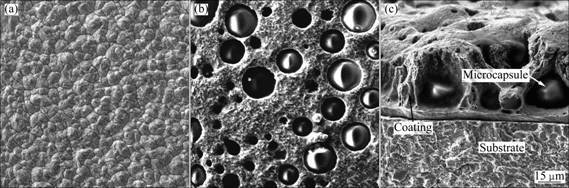
Fig. 1 SEM images of coatings: (a) Pure copper coating; (b) Copper/liquid microcapsule composite; (c) Cross-section of composite coating
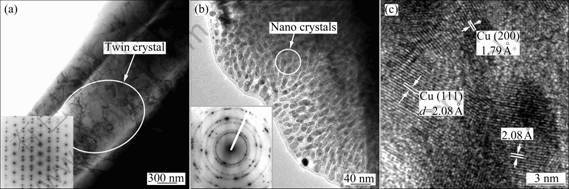
Fig. 2 TEM images of pure Cu (inset shows SAED pattern) (a), and composite (inset shows SAED pattern) (b) and HRTEM image from circle area of copper/liquid microcapsule composite (c)
Based on the experiment results above, it can be concluded that nanostructure transition happened after microcapsules were deposited in plating copper coating. Correspondingly, the grain sizes changed from micro-grade of copper coating to nano-grade of composite and the microstructure of composite also transformed to polycrystalline structure. To verify the crystal structure of the whole coatings, XRD analysis was performed. Figure 3 shows the XRD patterns of copper coating and composite. As shown, there are diffraction peaks characterizing face-centered cubic (FCC) structure of copper (JCPDS card No. 04��0836). The preferential orientation is Cu (220) for the copper coating. However, the obvious preferential orientation becomes weak for the composite coating, the preferential diffraction intensities of Cu (111) and Cu (200) increase obviously and their diffraction peaks become wider than those of pure copper, which indicates the refinement of grains of composite. The average size of nano-crystalline composite coating is about 30 nm according to the Scherer��s formula, which is in accordance with the grain size observed by TEM in Fig. 2(a).
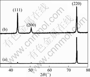
Fig. 3 XRD patterns of pure copper coating (a) and composite coating (b)
Figure 4 presents the cathodic polarization curves of the acidic sulfate copper-plating baths with and without microcapsule emulsion. It can be seen that the addition of microcapsule emulsion to the electrolyte results in the cathode polarization and makes the cathodic potential more negative. The concentration of metal cation in the electrolyte decreases when microcapsule emulsion is added to plating bath. Simultaneously, the existence of microcapsules increases the difficulty of mass transfer and the solution resistance. These are favorable to cathodic polarization and further lead to the formation of fine and homogeneous coating. Besides, the following reasons may also cause the refinement of composite grains: 1) plenty of Cu ions absorb onto the surface of microcapsules, which can enhance the nucleation chance of Cu ions; 2) deposited microcapsules as the second phase particles can inhibit the growth of copper crystals; 3) electroplating bath contains unencapsulated liquid core and shell materials, which can form a film at defects of growing grain surface and hinder grains to continue growth. So the grains of composite are refined obviously compared with that of pure copper coating.
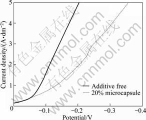
Fig. 4 Cathodic polarization curves of acidic sulfate copper baths with and without microcapsule emulsion
According to our previous experiment result from Ref. [15], addition of microcapsules to the electrolyte, even at a low concentration of 4% (volume fraction), caused the cathode to polarize. Although the shell and core of microcapsule in this study are different from those of microcapsule reported in Ref. [13], the polarization degrees that they cause are similar. The content of microcapsules in composite and the deposition rate decrease when the addition of microcapsules to the electrolyte is beyond 25% (volume fraction) [14]. So the nanostructured composite may be obtained when the addition of microcapsules emulsion exceeds a certain concentration. Additionally, it is found that the electroplating time also affects the formation of nano-crystals. The specific electrodeposition process parameters to obtain nanostructured composite need to be further studied.
3.2 Deposition mechanism of Cu/liquid microcapsules composite
As we known from above, electrolytic co-deposition of liquid microcapsules with metal ions in an acidic copper-plating bath was successfully carried out. Moreover, the nanostructured composite was obtained because of the participation of liquid microcapsules during the electrolytic co-deposition process. At present, many articles have been published describing the elecrodepositon mechanism of composite containing solid particles, such as Guglielmi��s model [18], the mechanical interception mechanism and the electrochemistry theory. However, few investigations have been concerned with composite containing liquid microcapsules. In our previous research [14-15], the size of the prepared liquid microcapsules was less than 10 ��m and a few quantity of microcapsules in the composite were found. Recently��it can be found that microcapsules with the diameter of 2-20 ��m are more beneficial to increasing the composite amount of microcapsules in plating coating. Therefore, we attempt to seek a theory to interpret the electrodeposition mechanism of this composite.
The electrochemistry theory holds that electrophoresis migration of charged particles under electric field force is a key factor influencing particles into plating coating. During the electrodeposition process, the cathode surfaces are with negative electric charges. Therefore, if the surface of particles has sufficient positive charges and the cathode polarization is greater, it is favorable to the co-deposition of metal ions and particles at high speed. Based on the electrochemistry theory, we think that it is more appropriate to explain the electrodeposition mechanism of composite containing liquid microcapsules with the size of 2-20 ��m. To verify this point, the movement of microcapsules under electric field force is analyzed by means of physical knowledge. It is hypothesized that microcapsule surface has positive charges and the charge density per unit area of microcapsules with different sizes is equal. According to the momentum theorem, the momentum equation of microcapsule in the plating bath should be:
 (2)
(2)
where F represents the electric field force, t is unit time, m and v refer to the quality and deposition speed of microcapsule, respectively. From Eq. (2) the following equation can be deduced:
 (3)
(3)
where E is the electric field which is a fixed value, q represents the total electric quantity of microcapsule, R and �� refer to the radius and the density of microcapsule, respectively. Because microcapsules can suspend in the plating bath, it is considered that the density of microcapsule is close to that of water. Thus, Eq. (3) is converted into:
 (4)
(4)
where ��0 is the charge density per unit area of microcapsule surface. Eq. (4) can be further simplified as:
 (5)
(5)
Here, E, �� and ��0 are fixed values. Therefore,
 (6)
(6)
Equation (6) implies that the smaller the radius of microcapsule is, the faster the deposition speed of microcapsule becomes. According to the theoretical analysis, the amount of microcapsules with small size should be greater than that of microcapsules with large size. As seen in Fig. 1(a), it can be confirmed that the experimental results are in accordance with the theoretical analysis conclusions above. Therefore, the hypothesis we made is correct, which illustrates the electrodeposition mechanism of composite following electrochemistry theory. Different from solid particles, liquid microcapsules are spherical in shape and its smooth external surface has certain elasticity. So it is easy to desorb from the growing copper coating and to return the bath for small sized microcapsules under the impact of subsequent microcapsules and copper ions.
Figure 5 depicts the electrodeposition process of Cu/liquid microcapsule composite. The force condition of microcapsule in the bath can be expressed in Fig. 5(d), where E represents the electric field F0 and G refer to the buoyancy and gravity of microcapsule, respectively.
Firstly, the microcapsules suspend in the plating bath in the absence of external electric field as seen in Fig. 5(a). At this time, the buoyancy is equal to the gravity of microcapsule. Secondly, the stable chelation between ��OH and ��O groups of shell material (MC) and metal ions (Cu2+) takes place��as shown in Fig. 5(b). Then the adduct ions with positive charge move towards cathode under the electric field force. Finally, these adduct ions are forced to deposit on the cathode surface at a high electrophoretic velocity (Fig. 5(c)).
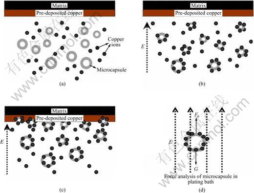
Fig. 5 Schematic diagrams of electrodeposition process for Cu/liquid microcapsule composite: (a) Initial state of plating bath; (b) Polymerization of ions under electric field force; (c) Adduct ions moving towards cathode; (d) Force analysis of microcapsule in plating bath
4 Conclusions
1) A nanostructured copper composite containing liquid microcapsule with the diameters of 2-20 ��m is obtained using DC electrodeposition. In the course of co-deposition, the participation of microcapsule emulsion causes the cathode polarization, increases the cathodic overpotential and refines the grains of composite.
2) TEM result shows the size of copper grains of composite is 10-20 nm.
3) The electrodeposition mechanism of composite follows electrochemistry theory and the microcapsules with the diameter of 2-20 ��m are more beneficial to deposition. Furthermore, the model of copper ions co-deposition with liquid microcapsules is put forward.
References
[1] KUO S L, CHEN Y C, GER M D, HWU W H. Nano-particles dispersion effect on Ni/Al2O3 composite coatings [J]. Mater Chem Phys, 2004, 86: 5-10.
[2] BALAJI R, PUSHPAVANAM M, YOGESH KUMAR K, SUBRAMANIAN K. Electrodeposition of bronze�CPTFE composite coatings and study on their tribological characteristics [J]. Surf Coat Technol, 2006, 201 (6): 3205-3211.
[3] BARCENA J, MAUDES J, COLETO J, BALDONEDO J L, de SALAZAR G J M. Microstructural study of vapour grown carbon nanofibre/copper composites [J]. Compos Sci Technol, 2008, 68(6): 1384-1391.
[4] IBRAHIM A, LIMA R S, BERNDT C C, MARPLE B R. Fatigue and mechanical properties of nanostructured and conventional titania (TiO2) thermal spray coatings [J]. Surf Coat Technol, 2007, 201(16-17): 7589-7596.
[5] WANG Y, XU Z. Nanostructured Ni-WC-Co composite coatings fabricated by electrophoretic deposition [J]. Surf Coat Technol, 2006, 200(12-13): 3896-3902.
[6] CHANG L M, AN M Z, GUO H F, SHI S Y. Microstructure and properties of Ni-Co/nano-Al2O3 composite coatings by pulse reversal current electrodeposition [J]. Appl Surf Sci, 2006, 253(4): 2132-2137.
[7] WANG Sheng-chang, WEI Wen-cheng. Characterization of electroplated Ni/SiC and Ni/Al2O3 composite coatings bearing nanoparticles [J]. J Mater Res, 2003, 18: 1566-1574.
[8] STEINBACH J, FERKEL H. Nanostructured Ni-Al2O3 films prepared by DC and pulsed DC electroplating [J]. Scripta Mater, 2001, 44 (8-9): 1813-1816.
[9] QU N S, CHAN K C, ZHU D. Pulse co-electrodeposition of nano Al2O3 whiskers nickel composite coating [J].Scripta Mater, 2004, 50(8): 1131-1134.
[10] ALEXANDRIDOU S, KIPARISSIDES C, FRANSAER J, CELIS J P. On the synthesis of oil-containing microcapsules and their electrolytic codeposition [J]. Surf Coat Technol, 1995, 71: 267-276.
[11] ZHU Li-qun, GUO Yan-hong, LI Wei-ping, LIU Hui-cong. Study on liquid microcapsules for electrolytic co-deposition [J]. Journal of Functional Materials, 2008, 39(9): 1507-1510. (in Chinese)
[12] ZHENG Tian-liang, ZHU Li-qun, ZHANG Wei. Corrosion resistance performance of liquid-containing microcapsule composite nickel and copper coating [J]. Acta Aeronautica Astronautics Sin, 2006, 27(1): 147-151. (in Chinese)
[13] ZHU Li-qun, ZHANG Wei, LIU Feng. Study on properties of composite copper coating with microcapsule [J]. Materials Engineering, 2004(1): 12-15. (in Chinese)
[14] GUO Yan-hong, LI Wei-ping, LIU Hui-cong, ZHU Li-qun. Influence of electrodepositing parameters on composite copper coating with liquid hydrophobic agent microcapsules [J]. Journal of Functional Materials, 2009, 40(3): 463-466. (in Chinese)
[15] ZHU Li-qun, ZHANG Wei, LIU Feng, HE Ying-he. Electrodeposition of composite copper/liquid-containing microcapsule coatings [J]. J Mater Sci, 2004, 39: 495-499.
[16] XU Xiu-qing, ZHU Li-qun, LI Wei-ping, LIU Hui-cong. Microstructure and deposition mechanism of electrodeposited Cu/liquid microcapsule composite[J]. Appl Surf Sci, 2011, (257): 5524-5528.
[17] GHOSH S K, Functional coatings by polymer microencapsulation [M]. Germany: WILEY-VCH, 2006: 297-341.
[18] LOW C T J, WILLS R G A, WALSH F C. Electrodeposition of composite coatings containing nanoparticles in a metal deposit [J].Surf Coat Technol, 2006, 201(1-2): 371-383.
�����Cu/Һ�����Ҹ��϶Ʋ���۽ṹ����������
������, ����Ⱥ, ����ƽ, ���۴�
�������պ����ѧ ���Ͽ�ѧ�빤��ѧԺ������ 100191
ժ Ҫ������ֱ����������Ʊ����ṹ��Cu/Һ�����Ҹ��϶Ʋ㡣����ɨ���������(SEM)�����������(TEM)��X��������(XRD)�����ͱ������϶Ʋ�ı�����ò���۽ṹ�������������������ʹ�ø��϶Ʋ��ɴ־��ṹת��Ϊ�����ṹ�����жƲ���Һ�����Ҽ�ͭ�����ijߴ�ֱ�Ϊ2~20 ��m ��10~20 nm�����⣬ͨ�����۷���֤ʵ��ͭ��Һ�����ҵĵ����������ѭ�绯ѧ�������������������Ӧ�ĵ��������ģ�͡�
�ؼ��ʣ�ͭ/Һ�����Ҹ��϶Ʋ㣻ֱ������������ṹ�����������
(Edited by YANG Hua)
Foundation item: Project (50771010) supported by the National Natural Science Foundation of China
Corresponding author: LIU Hui-cong; Tel: +86-10-82317113; Fax: +86-10-82317133; E-mail: liuhc@buaa.edu.cn
DOI: 10.1016/S1003-6326(11)60997-7

