J. Cent. South Univ. (2016) 23: 2941-2950
DOI: 10.1007/s11771-016-3358-8

On the accuracy of higher order displacement discontinuity method (HODDM) in the solution of linear elastic fracture mechanics problems
Abolfazl Abdollahipour, Mohammad Fatehi Marji, Alireza Yarahmadi Bafghi, Javad Gholamnejad
Faculty of Mining and Metallurgical Engineering, Yazd University, Yazd, P.O. Box, 89195-741, Iran
 Central South University Press and Springer-Verlag Berlin Heidelberg 2016
Abstract: The higher order displacement discontinuity method (HODDM) utilizing special crack tip elements has been used in the solution of linear elastic fracture mechanics (LEFM) problems. The paper has selected several example problems from the fracture mechanics literature (with available analytical solutions) including center slant crack in an infinite and finite body, single and double edge cracks, cracks emanating from a circular hole. The numerical values of Mode I and Mode II SIFs for these problems using HODDM are in excellent agreement with analytical results (reaching up to 0.001% deviation from their analytical results). The HODDM is also compared with the XFEM and a modified XFEM results. The results show that the HODDM needs a considerably lower computational effort (with less than 400 nodes) than the XFEM and the modified XFEM (which needs more than 10000 nodes) to reach a much higher accuracy. The proposed HODDM offers higher accuracy and lower computation effort for a wide range of problems in LEFM.
Key words: accuracy; higher order displacement discontinuity method; LEFM; mode I stress intensity factor; mode II stress intensity factor
1 Introduction
The boundary element methods have been extensively used in the field of linear elastic fracture mechanics (LEFM). The dual boundary element method (DBEM) incorporating two pairs of independent boundary integral equations is used extensively in the analyses of crack propagation process and fatigue [1-9]. NATARAJAN et al [10] proposed an XFEM method for SIF computation and SIMPSON and TREVELYAN [11] developed an enriched BEM and dual BEM to accurately compute the SIFs. The displacement discontinuity method (DDM) which is an indirect boundary element method is especially efficient for LEFM problems. It is based on a solution which expresses the stresses and displacements at a point due to a constant displacement discontinuity over a line segment in an elastic body [12]. Constant displacement discontinuity elements are simple to use and are widely utilized in analyzing engineering problems [13-16]. However, these models, fail to accurately predict the stresses and displacements for field points near boundaries. Also due to the singularity variations and
and for the stresses and displacements near the crack ends, the accuracy of the displacement discontinuity method at the vicinity of the crack tip decreases [17-19]. These shortcomings have been resolved by using higher order displacement discontinuity (HODD) elements [20-21]. CRAWFORD and CURRAN [20] used linear and quadratic displacement discontinuity elements to achieve better results. Since then HODD have been developed and used to achieve higher accuracy in LEFM problems [22-27]. Higher order elements increase the accuracy of the numerical results, but the problem of the crack tip singularities cannot be solved efficiently. The use of the crack tip elements can substantially improve the accuracy of the method for crack analyses [12, 28]. This paper uses the cubic variation of displacement discontinuity elements as ordinary higher order elements and four special elements for the treatment of crack tips in HODDM. Then, several example problems are solved by the proposed method and the results of Mode I and Mode II SIFs are compared with corresponding analytical results cited in the fracture mechanic literature. The effect of number of elements, the ratio of crack tip length to the original crack length (l/a) and the ratio of crack length to specimen width (a/w) are also investigated. Some outlines have been proposed for the ratio of l/a and ratio of a/w for finite body problems.
2 Higher order displacement discontinuity formulation
Four special crack tip elements accompanying cubic boundary elements are implemented in a higher order displacement discontinuity method to investigate the effect of these elements on the accuracy of the Mode I and Mode II SIFs results in several fracture mechanics problems.
The DDM permits crack surfaces to be discretized and computes crack opening displacements (normal displacement discontinuity), and crack sliding displacements (shear displacement discontinuity) directly as a part of the solution for each element [28].
2.1 Formulation of cubic displacement discontinuity elements
A cubic DD element (Dk(��)) is divided into four equal sub-elements. Each sub-element contains a central node for which the nodal DD is evaluated numerically (the normal and shear displacement discontinuity components Dy and Dx respectively) [29].
 (1)
(1)
where Dk1(i.e. Dx1 and Dy1 ), Dk2(i.e. Dx2 and Dy2 ), Dk3 (i.e. Dx3 and Dy3), and Dk4 (i.e. Dx4 and Dy4), are the cubic nodal displacement discontinuities and
 (2)
(2)
are the cubic collocation shape functions using a1=a2= a3=a4. A cubic element is shown in Fig. 1. The potential functions f(x, y), and g(x,y) for the cubic case are derived from
 (3)
(3)
in which the common function, Fj, is defined as

 (4)
(4)
where the integrals I0, to I3 are expressed as follows:
 (5)
(5)
and ��1, ��2, r1 and r2 are defined as

 (6)
(6)
The partial derivatives of I3 which are used to calculate displacement discontinuities are provided in appendix A. I0, I1 and I2 are completely explained by the first author in Ref. [28].
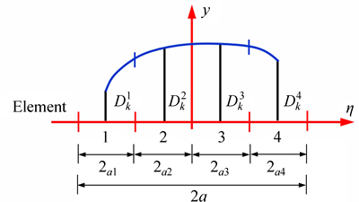
Fig. 1 Cubic collocation for cubic element displacement discontinuity
2.2 Formulation of special crack tip elements
Since the singularities of the stresses and displacements near the crack ends may reduce their accuracies, special crack tip elements are used to increase the accuracy of the DDs near the crack tips [28]. As shown in Fig. 2, the DD variation for four nodes can be formulated using a special crack tip element:
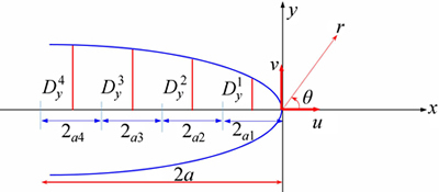
Fig. 2 Displacement correlation technique for special crack tip element [28]
containing four nodes (or having four special crack tip sub-elements).

 (7)
(7)
where the crack tip element has a length a1=a2=a3=a4.
Considering a crack tip element with the four equal sub-elements (a1=a2=a3=a4), the shape functions NC1(��) to NC4(��) can be obtained as
 (8)
(8)
Substituting Eq. (7) into Eq. (3) and rearranging the terms, a common special function FC(x, y) can be obtained as


 (9)
(9)
The singular integrals are included in the common special function FC(x, y) which can be abbreviated as
 (10)
(10)
Then, following special singular integrals can be deduced from Eq. (10) as
 (11)
(11)
The special singular integrals IC1, IC2, and IC3 previously are solved by the first author in Ref. [28]. The solution of IC4 is provided in appendix B. Based on the linear elastic fracture mechanics (LEFM) principles, the Mode I and Mode II stress intensity factors (SIFs) KI and KII can be easily deduced [28, 30]. Consideing a crack tip element of length 2a, then the SIFs with respect to the normal and shear displacement discontinuities (assuming plane strain condition), can be determined [31] as

 (12)
(12)
where �� is the shear modulus and �� is Poisson ratio of the brittle material.
Several well-known problems in the field of fracture mechanics have been chosen to investigate the accuracy and applicability of the problem. Following properties have been used in all problems: far-field or boundary stress ��=10 MPa, modulus of elasticity E=10 GPa, Poisson ratio v=0.2 and fracture toughness KIC=2 MPa��m1/2 geometrical parameters are given in each problem.
3 Center slant crack under far field uniform tension
The center slant crack under far field uniform tension is shown in Fig. 3. The slant angle, ��=45�� and half crack length a=1 m are assumed in the analysis. A crack tip element length to half crack length ratio, l/a= 0.1 has been used for the numerical solution of the problem. The analytical solution of the first and second mode SIFs, KI and KII, for the center slant crack problem are given as [32-33]
 (13)
(13)
Figure 4 shows the results obtained by various higher order crack tip elements using, DDM (with constant displacement discontinuity elements) [29, 34], and HODDM (with cubic displacement discontinuity elements) against analytical result obtained by Eq. (13).
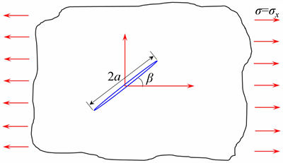
Fig. 3 Center slant crack in an infinite body under far field tension
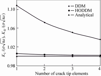
Fig. 4 Normalized modes I and II SIFs using DDM and HODDM with various number of crack tip elements
The results in Fig. 4 show that using more crack tip elements has increased the accuracy of both methods; however, HODDM gives very accurate results and is much more efficient than the DDM. The most accurate results have been obtained when using four crack tip elements in both DDM and HODDM; however, the error in DDM is around 3.6% while HODDM has predicted SIFs with less than 0.2% error.
Another center crack problem (��=90��), has been solved to compare the results with an XFEM method proposed by NATARAJAN et al [10]. They used Schwarz�CChristoffel conformal mapping (SC Map) for numerical integration. Figure 5 shows the results of HODDM, standard XFEM, and XFEM + SC Map proposed in Ref. [10]. They succeeded in improving the accuracy of the XFEM; however, their accuracy is still not comparable with the accuracy of HODDM. Using only a small number of elements (less than 400 nodes) in HODDM compared to the XFEM methods (more than 10000 nodes), a much more accurate result has occurred.
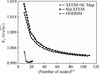
Fig. 5 Comparison of normalized stress intensity factor,  for center crack problem (obtained by proposed HODDM and XFEM methods given in Ref. [10])
4 Center slant crack in a finite plate
SIMPSON and TREVELYAN [11] developed an enriched BEM and dual BEM to accurately compute the SIFs. Their formulation makes use of the Partition of Unity Method (PUM) such that functions obtained from a priori knowledge of the solution space can be incorporated in the element formulation. The problem of a central inclined crack in a finite plate (see Fig. 6) is analyzed with results of SIMPSON and TREVELYAN for the case of a/w=0.5, h/w=2 and ��=45��. Results obtained by MURAKAMI [35] are used for reference. Figure 7 shows the normalized SIF for different methods using various number of elements along the crack. Although using 2 enriched crack tips has improved the accuracy of by results SIMPSON and TREVELYAN, but HODDM (using cubic and four special crack tip elements) yet has provided better results than enriched BEM. Using any number of elements more than 36 has resulted in less than 0.001% error in HODDM.
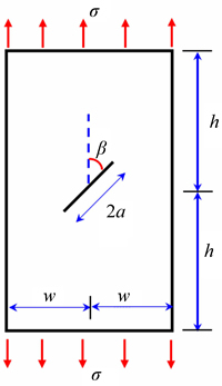
Fig. 6 Inclined center crack in a finite plate
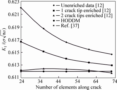
Fig. 7 Mode I results for inclined center crack, comparison of different methods
5 Single edge-cracked specimen
The calculation of stress intensity factors for the single edge-cracked geometry has received much attention due to its frequent use as a test specimen in LEFM. Consider a single edge-cracked geometry as shown in Fig. 8. The analytical solution to this problem is given as [30]
 (14)
(14)
For the problem shown in Fig. 8, let the width of the plate, w=1 m, a/w=0.1, then from Eq. (14) the analytical normalized value of
The single edge crack problem in a finite plate has been solved using proposed HODDM with cubic and four special crack tip elements in this paper. Figure 9 shows the effect of the number of elements along the crack on the value of normalized SIF ( ) for a single edge crack problem. Using more than 9 elements along the crack has reduced the error to less than 0.1%.
Let the ratio of crack tip element length, l, to crack length, a, changes as l/a=0.05, 0.1, 0.15, 0.2, 0.25, 0.3, 0.35 and 0.4 and take the number of the element along the boundaries of the problem as 60 and those along the crack as 10, the computed results forare compared with the corresponding analytical value (Fig. 10). It is shown that using l/a>0.15 considerably decreases the accuracy of HODDM for the single edge crack problem.
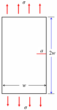
Fig. 8 A single edge-cracked specimen with w=1 m
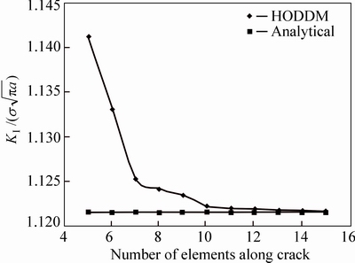
Fig. 9 Analytical and numerical values of normalized Mode I SIF,  , for single-edge cracked specimen, using different number of elements along crack and l/a=0.1
Figure 11 shows the effects of the different crack length to width ratio (different a/w ratios) on the value of for a single edge crack problem. For a/w<0.2, the error in SIF computation is less than 1%.
6 Double edge cracked plate
The double edge cracked plate is a common specimen in research and practice of fracture mechanics. The accuracy and applicability of the proposed HODDM are investigated through the computation of Mode I SIF for this problem. Consider a double edge cracked plate as shown in Fig. 12. The analytical solution to this problem is given as [34]
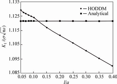
Fig. 10 Analytical and numerical values of normalized Mode I SIF,, for single-edge cracked specimen using different crack tip length to crack length ratio (l/a)
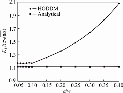
Fig. 11 Numerical values of normalized Mode I SIF, , for single edge crack using different crack length to width ratio (different a/w ratios)

 (15)
(15)
For the problem shown in Fig. 12, the same properties as those in the single-edge cracked problem are used. The problem is solved by HODDM. Figure 13 shows the effect of the number of elements along the crack on the value of normalized SIF for a double edge crack problem. Again the use of more than 9 elements has reduced the error in SIF computation to less than 0.1%.
The accuracy of the HODDM is tested against various number of crack tip to crack length ratios in Fig. 14. The number of boundary elements is kept at 60 and that along the crack as 10.
The computed results for  are compared with the corresponding analytical value in Fig. 14. Once more the use of l/a > 0.15 has reduced the accuracy of the HODDM.
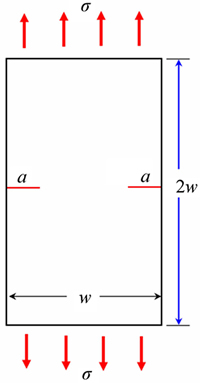
Fig. 12 Double edge crack in a finite plate with w=1 m
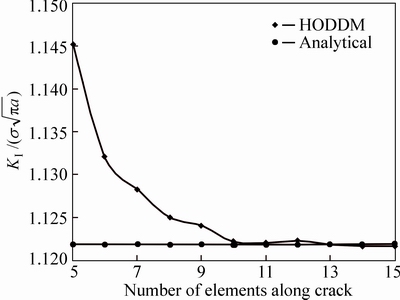
Fig. 13 Analytical and numerical values of normalized Mode I SIF, , for double edge crack, using different number of elements along crack and l/a=0.1
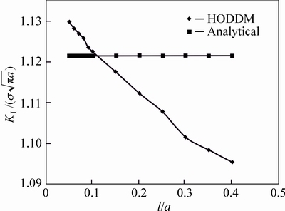
Fig. 14 Analytical and numerical values of normalized Mode I SIF, , for double edge crack using different crack tip length to crack length ratio (different l/a ratios)
Figure 15 shows the effect of the different crack length to width ratios (different a/w ratios) on the value of for a double edge crack problem. The accuracy of the HODDM decreases as a/w increases. The rate of reduction in accuracy has increased considerably for a/w >0.25.
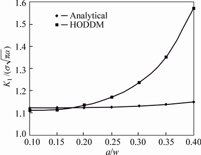
Fig. 15 Numerical values of normalized Mode I SIF, , for double edge crack using different crack length to width ratio (different a/w ratios)
7 Emanating cracks from a circular hole
Cracks emanating from a circular hole are of significant engineering importance, especially in the petroleum industry. Accurate determination of key fracture mechanics parameters is essential for hydraulic fracturing design and production rate. The geometry of the problem is depicted in Fig. 16. The problem is solved using HODDM and results are compared with the solution provided by TADA et al [34].
Using the line of symmetry shown in Fig. 16 only one-half of the problem is modeled. A symmetry line may be incorporated in the HODDM by including the effects of image boundary elements in the influence coefficients similar to that proposed by CROUCH and STARFIELD [23].50 elements on the circular hole and 10 elements along the crack have been used. Normalized SIF for different l/a ratios is compared with the corresponding analytical value in Fig. 17. It can be seen that the best results has been obtained at l/a =0.3 where the error is less than 0.2%.
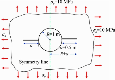
Fig. 16 Circular hole with two emanating cracks
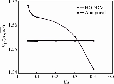
Fig. 17 Analytical and numerical values of normalized Mode I SIF, , for emanating cracks from a circular hole using different crack tip length to crack length ratios (l/a)
8 Discussion
The effects of number of elements, l/a and a/w on Modes I and II SIFs were investigated and best options were determined for each case. Besides the higher accuracy of the HODDM among other numerical methods, it should be noted that the number of elements for reaching the mentioned accuracy was substantially less than other methods. While the FEM and XFEM are not comparable in number of elements to HODDM (compare number of nodes in Fig. 5 for FEM, XFEM and HODDM). XBEM also needs more number of elements to be comparable to HODDM.
Several selected problems which are well-known infinite problems (i.e. center slant crack under far-field tension, cracks emanating from a circular hole) and test specimen problems (i.e. center slant crack in finite plate and single and double edges cracked plates) were investigated. A symmetry line was used in section 8 for the problem (which can be considered a simple hydraulic fracture case) to compute Mode I SIF. It should be noted that symmetry lines cannot be used when the crack propagation is investigated since the cracks will not follow the exact same path at both sides of the symmetry lines.
9 Conclusions
Higher order elements have significantly improved the accuracy of the DDM. In this paper, the HODDM implementing cubic boundary elements and four special crack tip elements has been introduced. The accuracy of the HODDM was investigated through comparison with analytical and other numerical solutions in the literature. It showed that the accuracy of HODDM lies among the most accurate methods. While the BEM is more efficient than other numerical methods (e.g. FEM and XFEM) because its semi-analytical approach, utilizing HODDM with cubic boundary elements and special crack tip elements have provided better results than other BEM methods. The accuracy of the proposed method was verified using the following steps. Several well-known problems in research and practice of fracture mechanics were studied. The results obtained by HODDM were compared with the corresponding results obtained by analytical and other numerical results in the literature. The HODDM demonstrated less than 0.2% error in all problems, showing high accuracy. It was shown that HODDM provides better results while using fewer elements hence improving efficiency and reducing computation time.
In the case of finite problems, some restrictions were met which should be noted and used as an outline to obtain the best results using HODDM. The length of crack to the width of the plate (a/w) should be less than 0.2. The length of the crack tip to crack length (l/a) should be less than 0.15 (best result l/a=0.1).
Appendix A
Cubic Integral I3, and its derivatives:


Let,
 ;
;
 ;
;
 ;
;
 and
and
 .
.
Therefore,


Appendix B
Special singular integral IC4 and its derivatives:


where,


and G1 and G2 are:


References
[1] GALVIS A F, SOLLERO P. 2D analysis of intergranular dynamic crack propagation in polycrystalline materials a multiscale cohesive zone model and dual reciprocity boundary elements [J]. Comput Struct, 2016, 164:1�C14.
[2] BENEDETTI I, ALIABADI M H, DAVI G. A fast 3D dual boundary element method based on hierarchical matrices [J]. Int J Solids Struct, 2008, 45: 922-933.
[3] DI PISA C, ALIABADI M H. Fatigue crack growth analysis of assembled plate structures with dual boundary element method [J]. Eng Fract Mech, 2013, 98: 200-213.
[4] THANH TU B, POPOV V. Boundary element dual reciprocity method with overlapping sub-domains [J]. Bound Elem Other Mesh Reduct Methods XXXI, 2008: 179-187.
[5] CHUANG S H, YUEH C Y, HUANG L H. Dual boundary element model coupled with the dual reciprocity method to determine wave scattering by a concentric cylindrical system mounted on a conical shoal [J]. Eng Anal Bound Elem, 2015, 56: 30-38.
[6] TAN M, WANG P, LI J, LIU Q, YANG Q. Numerical simulation and fracture evaluation method of dual laterolog in organic shale [J]. J Appl Geophys, 2014, 100: 1-13.
[7] YUN B I, ANG W T. A dual-reciprocity boundary element approach for axisymmetric nonlinear time-dependent heat conduction in a nonhomogeneous solid [J]. Eng Anal Bound Elem, 2010, 34: 697-706.
[8] KAMALI YAZDI A, OMIDVAR B, RAHIMIAN M. Improving the stability of time domain dual boundary element method for three dimensional fracture problems: A time weighting approach [J]. Eng Anal Bound Elem, 2011, 35: 1142�C1148.
[9] ROMLAY F R M, OUYANG H, ARIFFIN A K, MOHAMED N A N. Modeling of fatigue crack propagation using dual boundary element method and Gaussian Monte Carlo method [J]. Eng Anal Bound Elem 2010, 34: 297-305.
[10] NATARAJAN S, MAHAPATRA D R, BORDAS S P A. Integrating strong and weak discontinuities without integration subcells and example applications in an XFEM/GFEM framework [J]. Int J Numer Meth Eng, 2010, 83: 269-294.
[11] SIMPSON R, TREVELYAN J. A partition of unity enriched dual boundary element method for accurate computations in fracture mechanics [J]. Comput Methods Appl Mech Eng, 2011, 200: 1-10.
[12] CROUCH S L. Solution of plane elasticity problems by the displacement discontinuity method I. Infinite body solution [J]. Int J Numer Methods Eng, 1976, 10: 301-343.
[13] BEHNIA M, GOSHTASBI K, MARJI M F, GOLSHANI A. The effect of layers elastic parameters on hydraulic fracturing propagation utilizing displacement discontinuity method [J]. Anal Numer Methods Min Eng, 2012, 3: 1-14.
[14] HAERI H, SHAHRIAR K, FATEHI MARJI M, MOAREF VAND P. Simulating the bluntness of TBM disc cutters in rocks using displacement discontinuity method [C// 13th Int Conf Fract. Beijing: International Congresson Fracture, 2013.
[15] FATEHI MARJI M, GHOLAMNEJAD J, EGHBAL M. on the crack propagation mechanism of brittle substances under various loading conditions [C]// 11th Int Multidiscip Sci Geo-Conference. Albena, Bulgaria: SGEM, 2011.
[16] HAERI H, SHAHRIAR K, FATEHI MARJI M, MOAREFVAND P. An experimental and numerical study of crack propagation and cracks coalescence in the pre-cracked rock-like disc specimens under compression [J]. Int J Rock Mech Min Sci Geomech Abstr, 2013, 67: 20-28.
[17] ABDOLLAHIPOUR A, FATEHI MARJI M, YARAHMADI- BAFGHI A, GHOLAMNEJAD J. Simulating the propagation of hydraulic fractures from a circular wellbore using the displacement discontinuity method [J]. Int J Rock Mech Min Sci, 2015, 80: 281-291.
[18] COURTESEN D L. Cavities and gas penetration from blasts in stressed rock with flooded joints [J]. Acta Astron, 1979, 6: 341-363.
[19] HAERI H, SHAHRIAR K, FATEHI MARJI M, MOAREFVAND P. A boundary element analysis of the crack propagation mechanism of random micro cracks in rock-like specimens under uniform normal tension [J]. J Min Environ, 2014, 6: 73-93.
[20] CRAWFORD A M, CURRAN J H. Higher order functional varriation displacement discontinuity elements [J]. Int J Rock Mech Min Sci Geomech Abstr, 1982, 19: 143-148.
[21] FATEHI MARJI M. Higher order displacement discontinuity method in rock fracture mechanics [D]. Yazd: Yazd University, 2015.
[22] ABDOLLAHIPOUR A. Crack propagation mechanism in hydraulic fracturing procedure in oil reservoirs [D]. Yazd: University of Yazd, 2015.
[23] CROUCH S L, STARFIELD A M. Boundary element methods in solid mechanics [M]. London: George allen & Unwin, 1983.
[24] FATEHI MARJI M. Modelling of cracks in rock fragmentation with a higher order displacement discontinuity method [D]. Ankara: Middle East Technical University, 1997.
[25] FATEHI MARJI M, HOSSEINI-NASAB H. Application of higher order displacement discontinuity method using special crack tip elements in rock fracture mechanics [C]// 20th World Min Congr Expo. Tehran: Tehran university, 2005: 699-704.
[26] ITOU S. Effect of couple-stresses on the Mode I dynamic stress intensity factors for two equal collinear cracks in an infinite elastic medium during passage of time-harmonic stress waves [J]. Int J Solids Struct, 2013, 50: 1597-1604.
[27] ABDOLLAHIPOUR A, FATEHI MARJI M, YARAHMADI- BAFGHI A, GHOLAMNEJAD J. Numerical investigation on the effect of crack geometrical parameters in hydraulic fracturing process of hydrocarbon reservoirs [J]. J Min Environ, 2016, 7: 205-214.
[28] FATEHI MARJI M, HOSSEINI NASAB H, KOHSARY A H. On the uses of special crack tip elements in numerical rock fracture mechanics [J]. Int J Solids Struct, 2006, 43: 1669-1692.
[29] FATEHI MARJI M, HOSSEINI-NASAB H, MORSHEDI A H. Numerical modeling of the mechanism of crack propagation in rocks under TBM disc cutters [J]. Mech Mater Struct, 2009, 4: 605-627.
[30] SANFORD R J. Principles of fracture mechanics [M]. USA: Prentice Hall, 2003.
[31] SHOU K J, CROUCH S L. A higher order displacement discontinuity method for analysis of crack problems [J]. Int J Rock Mech Min Sci Geomech Abstr, 1995, 32: 49-55.
[32] GUO H, AZIZ N I, SCHMITT L C. Linear elastic crack tip modeling by displacement discontinuity method [J]. Engin Fract Mech, 1990, 36: 933-943.
[33] WHITTAKER B N, SINGH R N, SUN G. Rock fracture mechanics, principles design and applications [M]. Netherland: Elsevier Science Ltd, 1992.
[34] TADA H, PARIS P C, IRWIN G R. The stress analysis of cracks handbook [M]. 3rd ed. New York: ASME, 2000.
[35] MURAKAMI Y. Stress intensity factors handbook [M]. Oxford, England: Pergamon Press, 1987.
(Edited by YANG Hua)
Received date: 2015-09-02; Accepted date: 2015-12-16
Corresponding author: Abolfazl Abdollahipour, PhD; Tel/Fax: +98-9124570897; E-mail: ab.abdollahipour@gmail.com

