B4C��ǿ�������ϲ��������¶ȵķǽӴ������Ͷ�Ŀ�����
��Դ�ڿ����й���ɫ����ѧ��(Ӣ�İ�)2015���1��
�������ߣ�A.TASKESEN K. KUTUKDE
����ҳ�룺271 - 283
�ؼ��ʣ����������ϲ��ϣ������¶ȣ�ĥ�𣻷ǽӴ��������Ҷȹ���
Key words��metal matrix composite; drilling temperature; wear; non-contact measurement; grey relation
ժ Ҫ�����ù�ѧ���¼ƶ��ڲ�ͬ���������µ�B4C���������ϲ��ϵ������¶Ƚ��зǽӴ��������о��˿��������������ٶȡ��������ʺ͵��߲��϶���������¶ȵ�Ӱ�졣������������¶Ⱥ͵���ĥ����������������Ż����������������������¶�Ӱ������������ҪΪ�������������������Լ�������������������������á������������������϶���������¶ȵ�Ӱ����Խ�С��������������С�������ٶȽϵͣ��������ʽϸߣ�����Ӳ�ʺϽ�ʱ�������¶Ƚϵ͡������Ż���������������Ի�ýϵ͵������¶Ⱥͽ�С�ĵ���ĥ��
Abstract: Non-contact measurements of machining temperatures were performed with optical pyrometer when drilling particle (B4C) reinforced metal matrix composites (MMCs) with different drills. The effect of particle content, cutting speed, feed rate and tool material on the maximum drilling temperature was investigated. The drilling parameters were optimized based on multiple performance characteristics in terms of the maximum cutting temperature and tool wear. According to the results, the most influential control factors on the cutting temperatures are found to be particle fraction, feed rate and interaction between the cutting speed and particle content, respectively. The influences of the cutting speed and drill material on the drilling temperature are found to be relatively lower for the used range of parameters. Minimum cutting temperatures are obtained with lower particle fraction and cutting speed, with relatively higher feed rates and carbide tools. The results reveal that optimal combination of the drilling parameters can be used to obtain both minimum cutting temperature and tool wear.
Trans. Nonferrous Met. Soc. China 25(2015) 271-283
A. TASKESEN1, K. KUTUKDE2
1. Industrial Design Engineering, Gazi University, Teknikokullar 06500, Ankara, Turkey;
2. Institute of Science and Technology, Gazi University, Teknikokullar 06500, Ankara, Turkey
Received 16 January 2014; accepted 22 May 2014
Abstract: Non-contact measurements of machining temperatures were performed with optical pyrometer when drilling particle (B4C) reinforced metal matrix composites (MMCs) with different drills. The effect of particle content, cutting speed, feed rate and tool material on the maximum drilling temperature was investigated. The drilling parameters were optimized based on multiple performance characteristics in terms of the maximum cutting temperature and tool wear. According to the results, the most influential control factors on the cutting temperatures are found to be particle fraction, feed rate and interaction between the cutting speed and particle content, respectively. The influences of the cutting speed and drill material on the drilling temperature are found to be relatively lower for the used range of parameters. Minimum cutting temperatures are obtained with lower particle fraction and cutting speed, with relatively higher feed rates and carbide tools. The results reveal that optimal combination of the drilling parameters can be used to obtain both minimum cutting temperature and tool wear.
Key words: metal matrix composite; drilling temperature; wear; non-contact measurement; grey relation
1 Introduction
Metal matrix composites (MMCs) exhibit some important properties such as high specific strength, excellent wear resistance, low thermal expansion and lightweight. Due to these superior properties, MMCs are used as a substitute for conventional materials in some engineering applications such as aerospace, electronics, automotive, medical and military industries. However, machining of these composites is difficult because of hard abrasive reinforcement particles causing higher cutting temperatures and rapid tool wear, thus leading to high cost, size error and poor surface [1].
Temperature generated during the drilling process is one of the significant parameters controlling the tool wear [2]. Furthermore, machining temperature tends to increase since the drill is embedded in the workpiece, softening the drill bit and shortening the tool life. Thus, the cutting tool may be used more effectively by knowing the temperature mechanisms dependent on the machining parameters and conditions. Since drilling operations come generally after turning or milling processes, undesirable hole quality results in some unfavorable consequences as well. For this reason, precisely measuring and analyzing the drill temperatures are significant in designing drills and machining parameters for longer tool life, lower surface roughness, better hole quality and improved mechanical properties of the workpiece [3].
There is almost no study in the literature regarding the drilling temperatures during drilling of MMCs. In the present work, a novel technique was developed for non-contact measuring of temperatures at cutting edge generated during the drilling of MMCs reinforced with different B4C particle fractions. The drilling parameters were set by Taguchi experimental design methodology. The influence of particle content, drill material, spindle speed and feed rate on the maximum cutting temperature was determined. The cutting parameters were optimized according to the temperatures and tool wear. Before introducing this research, a brief review of the drilling temperature and existing temperature measuring techniques used for the drilling operations was presented.
2 Literature studies on drilling temperature
Literature studies on the drilling of MMCs focus primarily on the cutting forces, tool wear, surface roughness and burr formation. However, analysis of drilling temperatures, which negatively affect the tool life and hole quality, is needed. Various measuring methods of drilling temperatures were developed in previous studies such as embedding wire and thermocouples into the workpiece (Fig. 1(a)) [4] or in drill (Fig. 1(b)) [5], drill-foil thermocouple system (Fig. 1(c)) [3], measurement of microhardness, scanning electron microscopy and thermosensitive images. On the other hand, few researchers used non-contact measuring methods to accurately measure the temperature of cutting edge (Fig. 1(d)) [6,7]. Additionally, knowing the response time of the measuring device is tremendously important when measuring the cutting temperatures [8-14].
The most widely used method of wire-workpiece (Fig. 1(a)), in which thermocouples are embedded in workpiece as near as the hole wall, has a number of disadvantages [3]. In this method, measured maximum temperature depends on heat conductivity of the drilled workpiece and contact ratio between the thermocouple and workpiece, as well as the response time of the system. Moreover, a separate wire and thermocouple must be embedded for each test specimen, and a great care must be taken to ensure that the thermocouple is embedded at the desired location. For example, under the same cutting conditions, temperature results of COZ et al [11] are different from those of ZEILMANN and WEINGAERTNER [14] due to the distance of the thermocouples from the hole wall.
In the method of tool-thermocouple system, a thin wire and thermocouples are epoxied in the clearance face of the drill near the cutting edge through the coolant holes of drill bit (Fig. 1(b)). This method also has a disadvantage that there is a distance between the thermocouples and the cutting edge. Literature studies state that the maximum machining temperature occurs on the secondary shear zone at the rake face of cutting tool (Fig. 2) [15]. However, the placement of thermocouples at this zone is impossible since they would be damaged. Furthermore, the drill temperature cannot be measured by this method with small diameter drills because they do not have coolant channels.
Unlike the thermocouple methods, non-contact measurement method has some advantages over the other methods mentioned above. The major advantage of this method is that it continuously measures the cutting edge temperatures, so the temperature values can be continuously stored through the drilling depth. BHOWMICK et al [6] indicated that temperature measurement by using non-contact infrared termometer was a practical and effective method. In this method, emissivity of the cutting tool might be needed.

Fig. 1 Temperature measurement methods during drilling process

Fig. 2 Temperature regions of metal cutting process [15]
In the previous studies on the machining temperatures, some researchers developed analytical and computational models to predict the temperatures during the drilling process. WU and HAN [16] studied the prediction of maximum drilling temperature by using finite element analysis. They indicated that their simulated results experienced a good agreement with the measured temperatures. BRANDAO et al [4] used an analytical model to evaluate the temperature, heat flux and convection coefficient when drilling AISI H13 steel by using new and worn drill bits with conditions of dry, minimal quantity lubrication (MQL) and coolant. The lowest cutting temperatures were found with the use of coolant, followed by MQL and dry conditions. BONO and NI [17] developed a model in order to predict heat flow in the workpiece during dry drilling by assuming that total heat formation was due to the sum of shearing and friction. This heat formation was correlated with the tool geometry and cutting forces. They experienced some measuring problems by embedding thermocouples close to the hole wall. They claimed that the uncertainty in the location of the thermocouples was a great problem in measuring the drilling temperatures.
With regard to the workpiece materials, most of the earlier studies on the temperature measurement deal with the drilling of steels such as AISI 1040, AISI 1045 and AISI H13 as well as Ti6Al4V alloys. In addition, there are limited studies on the polymer composites [18], magnesium alloys, cast iron and aluminum alloys [3,7,13]. Some researchers stated that drilling temperature increases as both cutting speed and feed rate increase due to increasing spent power [3,7,13,16,18]. Moreover, increasing rate of the temperature decreases with the increase in feed rate [13]. In addition, increasing drilling depth or hole number has an effect on the temperature increase when intermittently drilling AISI 1040 and Al 7075-T651 alloy [9,12]. However, there is a different study pointing out that drilling temperature decreases as feed rate increases [12]. Minimum drilling temperature was obtained with a combination of lower spindle speed, higher feed rate and lower cutting depth when drilling Ti6Al4V alloy [11,14,19]. BAGCI and OZCELIK [8] implied that influence of drilling depth on the cutting temperature is important, but that of cutting speed and feed rate is insignificant. Figure 3 depicts the maximum measured temperatures found in the literature when drilling different types of workpiece materials. According to these results, maximum drill temperatures are seen during drilling of titanium and AISI carbon steels, while the minimum tool temperatures are observed during the drilling of aluminum alloys [7]. With respect to coolant conditions, decrements of the cutting temperature during flooded turning, milling and drilling are nearly 5%, 10%-15% and 20%-25%, respectively, as compared to dry machining [7]. Drilling with cutting fluid through coolant channels of the drill bit helps the temperature to maintain at a constant level and to decrease by 50% [19]. Furthermore, the maximum temperatures while the drilling under MQL condition do not exceed the temperatures during wet circumstances [6]. On the other hand, around 50% reduction in the temperatures is obtained with MQL applied through the coolant holes as compared with MQL applied with an external nozzle [14].

Fig. 3 Maximum temperature values observed during drilling of various workpieces in literatures
In previous studies, there are different results regarding the place of maximum cutting temperature on the drill bit. For example, according to some researchers, the maximum drilling temperature occurs close to the chisel edge [16, 20]. However, UEDA et al [7] argued that drilling temperature on the cutting edge increases linearly with increasing distance from the drill center, and it reaches the highest value near the drill corner. In addition, BONO and NI [20] found that the temperature rises with an increase in point angle.
3 Experimental
3.1 Materials
In this work, matrix material of the workpiece was 7xxx series aluminum alloy and its chemical composition was 5% Zn, 3.5% Cu, 2.5% Mg (mass fraction) and balanced Al. Three reinforcement materials of 10%, 15% and 25% B4C (mass fraction) with an average particle size of 30 ��m were used. The composites were produced by powder metallurgy (PM) method in prismatic dimensions of 50 mm��70 mm��12 mm. This method was similar to the fabrication route used by previous researchers [21-25]. Mechanical properties of the workpieces are listed in Table 1.
Table 1 Mechanical properties of composites

3.2 Plan of experiments and drilling process
With regard to experimental design, Taguchi��s L27 (313) orthogonal array was chosen since it has the ability to control the interactions among the factors [26]. For drilling experiments, control factors and levels of each parameter are given in Table 2. Total of 108��2 holes were drilled according to Taguchi��s 27 experiments for confirmation purpose. Drilling experiments were performed with CNC controlled vertical machining center (VMC-550 Johnford Fanuc Series O-M) having the capacity of 15 kW and 3500 r/min under dry machining conditions. The materials and geometrical properties of the drill bits are listed in Table 3.
3.3 Measurements
Before measuring the drilling temperatures, emissivity values of the cutting tools at different temperatures were experimentally obtained. For this purpose, drill bits were heated between 300 ��C and 900 ��C in a furnace, of which the temperature was preset. At that time, emissivity values of each drill bit were measured and recorded using the optical pyrometer.
Table 2 Drilling parameters and levels

For non-contact measuring of the temperatures in inaccessible regions, measuring device needs to get sight of that region. During the drilling process, contactless measurement of the tool��s cutting edge temperature is difficult due to the embedded drill bit. In order to overcome this difficulty, the drilling experiments were performed with the workpieces having 24 pre-drilled holes of 1 mm (Fig. 4). In addition, flank wears of the drill bits were measured with a Mitutoyo�CTM�C20X optical microscope having 5 ��m accuracy.
Technical specifications and arrangement of the laser pyrometer used in the experiments are illustrated in Fig. 5. The pyrometer has different spot diameters according to the distance, as seen in Fig. 5(a). In this work, drilling temperatures were measured at distance from 150 mm to the cutting edge (Fig. 5(b)). Therefore, the optical pyrometer has to move together with the cutting tool in order to maintain this distance and spot diameter. For this purpose, a fastening device for the pyrometer was designed and manufactured, as seen in Fig. 6. One end of the fastening device was mounted on the machine tool��s spindle and the other end was fixed with the pyrometer. Later, parallelism of the pyrometer in three axes (x, y, z) was arranged by using a dial gauge. Distance of 150 mm in feed direction between the middle of the cutting edge and pyrometer was adjusted. Hence, pyrometer moved at the same speed with the feed rate keeping the 150 mm distance during the drilling process. Finally, drilling temperatures were recorded by using Compact Connect software.
Figure 7 depicts typical temperature variations at the cutting edge of the drill bit. As the drill bit goes deep, more heat is generated because of the formation of chips and friction at the tool��s clearance face [4]. In this graph, the temperature started with 300 ��C since the measuring range of the device was between 200 ��C and 1200 ��C, as seen in Fig. 5.
Table 3 Cutting tool properties


Fig. 4 Composite specimen with pre-drilled 24 holes by EDM machine

Fig. 5 Technical specifications, focal length and spot distance of non-contact temperature measurement device (a), and arrangement of pyrometer (b)
4 Results and discussion
4.1 Emissivity values of cutting tools
Non-contact measuring instruments generally measure the temperatures according to the emissivity (��) values of the materials, which are determined from experiments. However, cutting tools have different emissivity values at different temperatures due to multiple material combinations. For this reason, emissivity values of the drill bits were measured at different temperatures between 300 ��C and 900 ��C with the optical pyrometer. Figure 8 shows the emissivity values of HSS, carbide and TiAlN coated carbide tools. Emissivity of cutting tools decreases until a temperature of approximately 500 ��C and then it increases.
4.2 Drilling temperatures
Average temperature variations of the cutting edge according to the machining parameters are shown in Fig. 9. As can be seen from Fig. 9, an increase of the feed rate results in a decrease in the temperature. This status can be explained by the easy flowing and discharging of chips, since 80% of the temperature generated on the drilling process is discharged with the chip [27,28]. Therefore, as the feed rate increases, generated chips will be easily discharged. Additionally, previous studies also argued that the drilling temperatures decreased with increasing feed rate owing to less contact time between hard particles and the cutting edge [12,19].

Fig. 6 Test setup for temperature measurement

Fig. 7 Typical temperature variations when drilling 25% composite with carbide tool at 1000 r/min and 0.1 mm/r
Figure 10 shows the response graphs of drilling temperature regarding the effects of factors on the tool temperature. The tool temperature increases with the reinforcement particle content by the reason of higher contact ratio and rubbing activity between the abrasive B4C particulates and cutting edge. This idea was supported by previous studies stating that abrasive forces and thus wear rate increased when density of the hard particle increased [29].

Fig. 8 Emissivity results of HSS, carbide and TiAlN coated carbide tools
Past studies indicated that there was an increase in heat formation during the drilling process depending on the increase of cutting speed leading to the friction forces [3,7,13,16,18,19]. In the present work, even though tool temperature increases with the spindle speed, variations in the tool temperature as a function of spindle speed are weak compared to those of particle fraction or feed rate (Fig. 10). The reason for this can be attributed to the tool wear mechanisms on the machining of ferrous and nonferrous materials. For example, flank and crater wears grow when the cutting speed is increased during the drilling of ferrous materials, as well as certain high strength alloys, due to higher interface temperature between the cutting tool and workpiece [30]. However, an increase in the cutting speed has a less influence on cutting temperature at the interface during the drilling of nonferrous materials. Accordingly, cutting speed does not significantly affect the cutting of aluminum alloys since the melting temperature of the aluminum alloys (550-660 ��C) is close to the softening temperature of the HSS tools (540-600 ��C) and is much smaller than that of carbide tools (870-1100 ��C) [31]. In addition, machining forces and temperatures are usually low due to good heat conductivity of the aluminum [32].

Fig. 9 Effects of process parameters on drilling temperature

Fig. 10 Mean response graphs of factors for drilling temperature
When test results were discussed in terms of the drill materials, low temperature was produced with carbide tools than HSS tools. The reason can be attributed to the hardness of drill bit and wear mechanisms on the cutting tool. The best results in terms of cutting temperatures were obtained with carbide, TiAlN coated carbide and HSS drills, respectively (Fig. 10).
4.3 Tool wear
Based on the experimental results, the most important tool wear mechanism was abrasive wear, and no edge chipping was observed after drilling for one time with each drill. Figure 11 shows the effects of drilling parameters on the flank wear. It can be deduced from this figure that the tool wear can improve if the feed rate is increased over the used range of feeds. Furthermore, a reduction of tool temperature with increased feed rate might be another influential cause of decreasing the tool wear or vice versa [33,34].
From Fig. 11(b), one can understand that flank wear increases with reinforcement content for all feed rates due to similar reasons of tool temperature mentioned before. More than that, the results of response graphs, presented in Fig. 12, the effects of factors on the tool wear showed that there was also nearly similar correlation between the drill temperatures and the tool wear with regard to the effects of machining conditions on the responses.

Fig. 11 Effects of process parameters on tool wear according to cutting tool and spindle speed (a) and feed rate and particle content (b)
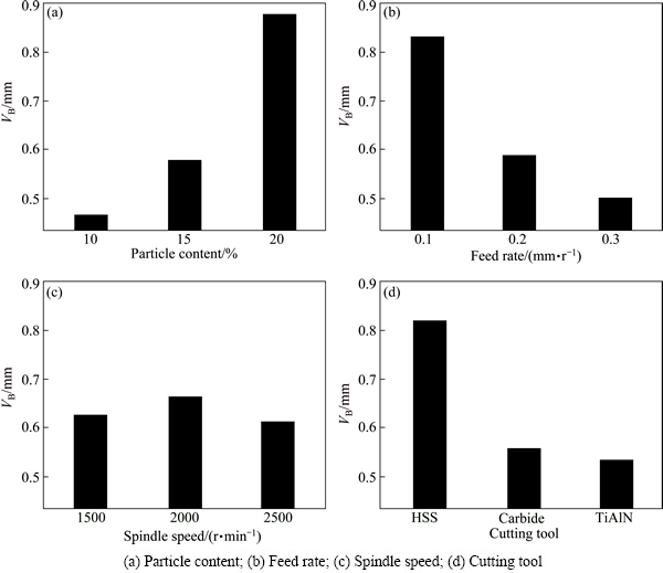
Fig. 12 Mean response graphs of factors for tool wear
4.4 Multi response optimization with grey relational analysis (GRA)
In this section, maximum drilling temperature and tool wear were simultaneously optimized with GRA, a valuable methodology for the design of qualitative and discrete parameters. With this method, the following steps are followed in order to optimize the process parameters:
1) The experimental results are normalized (data pre-processing).
2) The grey relational coefficient and grey relational grade are computed.
3) The experimental results are analyzed.
4) The optimal levels of the process parameters are selected.
5) The optimal parameters through the confirmation experiments are verified.
Experimental results for the maximum tool temperature (tmax) and tool��s flank wear (VB) conducted by using L27(313) orthogonal array are given in Table 4. For calculating the grey grade, the maximum temperature of the tool and tool wear were normalized in the range between zero and one [35,36]. This process is called the data pre-processing, and is required due to the different range and unit of each data. Data pre-processing transfers the original sequence to a comparable one. In this work, calculation method of ��the smaller the better�� was used since minimization of the temperature and tool wear is intended. For calculating the normalized value of the j-th response of the k-th experiment, Zj(k), the following expression can be used:
 (1)
(1)
where Yj(k) is the original value to be normalized, maxj[Yj(k)] is the largest value of Yj(k), and min[Yj(k)] is the smallest value of Yj(k).
For example, the normalized value for j=1-2, k=1-27 can be computed as follows:
Y1(1)=(496.7-299.4)/(496.7-273.4) =0.8836 (2)
Y2(1)=(1.78-0.66)/(1.78-0.36)=0.7887 (3)
The normalized values for Tmax and VB are presented in Table 4.
Table 4 Taguchi experimental design, normalized values and grey grades for tool��s maximum temperature (Tmax) and tool�� flank wear (VB)

4.4.1 Computing grey relational coefficient and grey relational grade
Grey relational coefficient ��(k) is calculated to express the relationship between the ideal and actual normalized experimental results. The grey relational coefficient e(k) can be expressed as follows [37,38]:


 (4)
(4)
where Z0(j) is the ideal sequence which has the value of 1, and ��j(k) is the grey relational coefficient of the j-th performance characteristic of the k-th experiment.
Distinguishing coefficient �� is defined in the range of 0�ܦΡ�1. It is generally taken as 0.5. If this coefficient is small, distinguishing capability would be higher (the value may be adjusted based on the practical needs of the system).
Grey relational grade (GRG, average value of the grey relational coefficients) is the geometrical similarity between Z0 and Zj in a grey system and it can take a value between zero and one, [0,1]. A higher grey relational grade indicates a strong relational degree between the comparative and ideal sequence. Grey relational grade ��k for the k-th experiment can be determined from the following equation:
 (5)
(5)
where n is the number of responses.
For example, the grey relational grade for the maximum tool temperature (Tmax) at level 1 can be calculated by averaging the grey relational coefficients as follow:
 (6)
(6)
The results of calculated grey relational coefficients ej(k) (j=1, ��, 2) and grey relational grade ��k (k=1, ��, 27) using Eq. (4) and Eq. (5), respectively, for different cutting conditions are given in Table 4. The calculated grey relational grades for each experiment were put in order from maximum (optimum) to minimum and then they were presented in the rightmost of the table. The optimal value, which was the maximum of grey relational grade, was found to be the 17th experiment for initial parameters (Table 4).
In the next step, the main effects of each factor were calculated from the value of grey relational grade. The maximum grey relational grades of each factor were calculated (Table 5) and effects of the factors are plotted in Fig. 13. By maximizing the grade values (Table 5 and Fig. 13), minimum of the temperature and tool wear can be simultaneously obtained at the A1B3C1D2 optimal machining conditions.
Table 5 Main effects of factors on grey grade

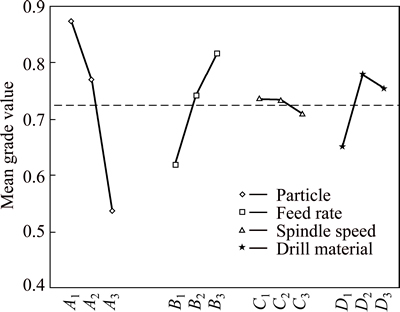
Fig. 13 Effect of each factor with regard to multiple performance on grey grade
4.5 Analysis of variance (ANOVA) for grey relational grade
Analysis of variance is applied to determine which parameter significantly influences the drilling temperature. In ANOVA, F-value of particle fraction (A) 533.31 designates that the particle fraction is significant with the probability of <0.0001. ��Prob F�� values less than 0.05 denote that the terms are significant [37]. In this situation, A, B, D, A��B and A��C are the significant terms which influence the grey grade in drilling MMCs (Table 6). According to the ANOVA results presented in Table 6, the most efficient factor on the grey grade is found to be particle content as 63.4%, followed by the feed rate (21.4%) and drill material (10.1%).
Table 6 ANOVA results for grey grade
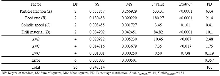
Table 7 Results of confirmation experiments
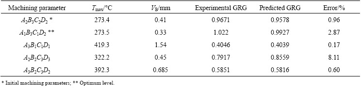
4.6 Optimal cutting conditions and confirmation experiments
In the final step, prediction and verification of the performance characteristics regarding the selected initial parameter setting were carried out. Confirmation experiments were performed to validate the applicability and reproducibility of the optimization method adopted in this work. Grey relational grade under the optimum conditions, ��predicted, is predicted by using the following model:
 (7)
(7)
where ��m is the total mean of grey relational grade, ��i is the mean grey relational grade at optimal level, and N is the number of main design parameters that significantly affect the multiple performance characteristics [35]. For example, predicted GRG at A1B3C1D2 optimal machining conditions can be calculated as following:
��predicted=��m+(A1-��m)+(B3-��m)+[(A1B3-��m)-(A1-��m)-(B3-��m)]+(C1- ��m)+[(A1C1-��m)-(A1-��m)-(C1-��m)]+[(B3C1-��m)-(B3-��m)-(C1- ��m)]+(D2-��m)
The results of the confirmation experiments for the optimal drilling conditions of A1B3C1D2 are found to be Tmax=273.5 ��C and VB=0.33 mm, respectively. Predicted grey grade with Eq. (7) is found to be 0.9927. In addition, Table 7 and Fig. 14 present the comparison between the predicted and experimental grey grades under different machining conditions. These results show that the predicted results are compatible with the confirmation experiments. Thus, the grey relational analysis is a very powerful method for estimating the grey relational grade in the drilling of Al/B4C reinforced MMCs.

Fig. 14 Comparison of grey relational grades
5 Conclusions
1) The influential factors on the tool temperature are found to be particle mass fraction and feed rate, respectively. Tool temperatures increase with the increase of reinforcement content.
2) For the used range of parameters, increasing the feed rate decreases the cutting temperature due to easy flowing and discharging of cut chips. Although tool temperature increases with the spindle speed, variations in the tool temperature as a function of spindle speed are weak compared to those of particle fraction or feed rate.
3) Regarding the cutting tools, lower temperatures are produced with carbide drills than that with HSS drills. The effect of the cutting parameters on the tool wear is found to be similar to that on the tool temperature.
4) From the grey relational analysis, the optimum level of particle content of B4C is 10%, feed rate is 0.3 mm/r, spindle speed is 1500 r/min and drill material is uncoated carbide tool. Hence, this method is useful in order to optimize the drilling parameters, considering simultaneously minimum tool temperature and tool wear, in drilling MMCs for the used range of levels.
Acknowledgments
This research was supported by Gazi University (07/2008-8). The authors thank TOBB Economy, Technology University and Prof. Dr. Mustafa UBEYLI for providing laboratory opportunities during the fabrication of the MMCs. Authors express their gratitudes to  and Mr. Serdar ISKENDER for enabling tensile and impact tests for fabricated composites.
References
[1] RAJMOHAN T, PALANIKUMAR K. Application of the central composite design in optimization of machining parameters in drilling hybrid metal matrix composites [J]. Measurement: Journal of the International Measurement Confederation, 2013, 46(4): 1470-1481.
[2] MATSUMURA T, HORI I, SHIRAKASHI T. Analysis of cuttinng temperature in drilling process [J]. International Journal of Material Forming, 2010, 3(S1): 499-502.
[3] BONO M, NI J. A method for measuring the temperature distribution along the cutting edges of a drill [J]. Journal of Manufacturing Science and Engineering, 2002, 124(4): 921-922.
[4] BRANDAO L C, COELHO R T, LAURO C H. Contribution to dynamic characteristics of the cutting temperature in the drilling process considering one dimension heat flow [J]. Applied Thermal Engineering, 2011, 31(17-18): 3806-3813.
[5] BAGCI E, OZCELIK B. Analysis of temperature changes on the twist drill under different drilling conditions based on Taguchi method during dry drilling of Al 7075-T651 [J]. International Journal of Advanced Manufacturing Technology, 2006, 29(7-8): 629-636.
[6] BHOWMICK S, LUKITSCH M J, ALPAS A T. Dry and minimum quantity lubrication drilling of cast magnesium alloy (AM60) [J]. International Journal of Machine Tools & Manufacture, 2010, 50(5): 444-457.
[7] UEDA T, NOZAKI R, HOSOKAWA A. Temperature measurement of cutting edge in drilling��Effect of oil mist [J]. Annals of the CIRP, 2007, 56(1): 93-96.
[8] BAGCIE,OZCELIKB.Effectsofdifferentcoolingconditionsontwistdrilltemperature[J].InternationalJournalofAdvancedManufacturingTechnology,2007,34(9-10):867-877.
[9] BAGCI E, OZCELIK B. Finite element and experimental investigation of temperature changes on a twist drill in sequential dry drilling [J]. International Journal of Advanced Manufacturing Technology, 2006, 28(7-8): 680-687.
[10] BAGCI E, OZCELIK B. Influence of cutting parameters on drill bit temperature in dry drilling of AISI 1040 steel material using statistical analysis [J]. Industrial Lubrication and Tribology, 2007, 59(4): 186-193.
[11] COZ G L, MARINESCU M, DEVILLEZ A, DUDZINSKI D, VELNOM L. Measuring temperature of rotating cutting tools: Application to MQL drilling and dry milling of aerospace alloys [J]. Applied Thermal Engineering, 2012, 36(1): 434-441.
[12] OZCELIK B, BAGCI E. Investigation of the effect of drilling conditions on the twist drill temperature during step-by-step and continuous dry drilling [J]. Materials and Design, 2006, 27(6): 446-454.
[13] OZCELIK B, BAGCI E. Experimental and numerical studies on the determination of twist drill temperature in dry drilling: A new approach [J]. Materials and Design, 2006, 27(10): 920-927.
[14] ZEILMANN R P, WEINGAERTNER W L. Analysis of temperature during drilling of Ti6Al4V with minimal quantity of lubricant [J]. Journal of Materials Processing Technology, 2006, 179(1-3): 124-127.
[15] RAJPUT R K. A textbook of manufacturing technology: Manufacturing processes [M]. New Delhi: Laxmi Publications Pvt Ltd, 2007: 391-392.
[16] WU J, HAN R D. A new approach to predicting the maximum temperature in dry drilling based on a finite element model [J]. Journal of Manufacturing Processes, 2009, 11(1): 19-30.
[17] BONO M, NI J. A model for predicting the heat flow into the workpiece in dry drilling [J]. Journal of Manufacturing Science and Engineering, 2002, 124(4): 773-777.
[18] WEINERT K, KEMPMANN C. Cutting temperatures and their effects on the machining behaviour in drilling reinforced plastic composites [J]. Advanced Engineering Materials, 2004, 6(8): 684-689.
[19] LI R, SHIH A J. Spiral point drill temperature and stress in high-throughput drilling of titanium [J]. International Journal of Machine Tools & Manufacture, 2007, 47(12-13): 2005-2017.
[20] BONO M, NI J. The location of the maximum temperature on the cutting edges of a drill [J]. International Journal of Machine Tools and Manufacture, 2006, 46(7-8): 901-907.
[21]  M, AC1R A,
  M S, DEMIR T. On the surface roughness of Al-4%Cu/B4C metal matrix composites machined by milling operation [J]. Science and Engineering of Composite Materials, 2008, 15(2): 131-139.
[22] M, ACIR A, SERDAR M,  B. Effect of feed rate on tool wear in milling of Al-4%Cu/B4Cp composite [J]. Materials and Manufacturing Processes, 2008, 23(8): 865-870.
[23] ACIR A, TURGUT Y,  A study on the cutting force in milling of boron carbide particle reinforced aluminum composite [J]. Science and Engineering of Composite Materials, 2009, 16(3): 187-195.
[24] YILBAS B S, KHAN S, RAZA K, KELES O, UBEYLI M, DEMIR T, KARAKAS M S. Laser cutting of 7050 Al alloy reinforced with Al2O3 and B4C composites [J]. International Journal of Advanced Manufacturing Technology, 2010, 50(1-4): 185-193.
[25] TASKESEN A, KUTUKDE K. Optimization of the drilling parameters for the cutting forces in B4C-reinforced Al-7xxx-series alloys based on the taguchi method [J]. Materials and Technology, 2013, 47(2): 169-176.
[26] TSAO C C. Taguchi analysis of drilling quality associated with core drill in drilling of composite material [J]. International Journal of Advanced Manufacturing Technology, 2007, 32(9-10): 877-884.
[27] ERTUNC H M, LOPARO K A, OCAK H. Tool wear condition monitoring in drilling operations using hidden Markov models (HMMs) [J]. International Journal of Machine Tools and Manufacture, 2001, 41(9): 1363-1384.
[28]  An experimental investigation of effect of cutting parameters on cutting zone temperature in drilling [J]. Journal of The Faculty of Engineering and Architecture of Gazi University, 2013, 28(1): 1-6.
[29] ALRASHDAN A, MAYYAS A T, HASSAN A M, HAYAJNEH M T. Drilling of Al-Mg-Cu alloys and Al-Mg-Cu/SiC composites [J]. Journal of Composite Materials, 2011, 45(20): 2091-2101.
[30] COELHO R T, YAMADA S, ASPINWALL D K, WISE M L H. The application of polycrystalline diamond (PCD) tool materials when drilling and reaming aluminium based alloys including MMC [J]. International Journal of Machine Tools and Manufacture, 1995, 35(5): 761-774.
[31] HAMADE R F, ISMAIL F. A case for aggressive drilling of aluminum [J]. Journal of Materials Processing Technology, 2005, 166: 86-97.
[32] TASKESEN A, KUTUKDE K. Analysis and optimization of drilling parameters for tool wear and hole dimensional accuracy in B4C reinforced Al-alloy [J]. Transactions of Nonferrous Metals Society of China, 2013, 23(9): 2524-2536.
[33] AHAMED A R, ASOKAN P, ARAVINDAN S, PRAKASH M K. Drilling of hybrid Al-5%SiCp-5%B4Cp metal matrix composites [J]. International Journal of Advanced Manufacturing Technology, 2010, 49(9-12): 871-877.
[34] DAVIM J P, MONTEIRO BAPTISTA A. Cutting force, tool wear and surface finish in drilling metal matrix composites [J]. Proceedings of the Institution of Mechanical Engineers, Part E: Journal of Process Mechanical Engineering, 2001, 215(2): 177-183.
[35] RAJMOHAN T, PALANIKUMAR K, KATHIRVEL M. Optimization of machining parameters in drilling hybrid aluminium metal matrix composites [J]. Transactions of Nonferrous Metals Society of China, 2012, 22(6): 1286-1297.
[36]  . Experimental investigation and multi-objective analysis on drilling of boron carbide reinforced metal matrix composites using grey relational analysis [J]. Measurement: Journal of the International Measurement Confederation, 2014, 47(1): 321-330.
[37] PALANIKUMAR K. Experimental investigation and optimisation in drilling of GFRP composites [J]. Measurement: Journal of the International Measurement Confederation, 2011, 44(10): 2138-2148.
[38] PALANIKUMAR K, LATHA B, SENTHILKUMAR V S, DAVIM J P. Analysis on drilling of glass fiber-reinforced polymer (GFRP) composites using grey relational analysis [J]. Materials and Manufacturing Processes, 2012, 27(3): 297-305.
A.TASKESEN1, K. KUTUKDE2
1. Industrial Design Engineering, Gazi University, Teknikokullar 06500, Ankara, Turkey;
2. Institute of Science and Technology, Gazi University, Teknikokullar 06500, Ankara, Turkey
ժ Ҫ�����ù�ѧ���¼ƶ��ڲ�ͬ���������µ�B4C���������ϲ��ϵ������¶Ƚ��зǽӴ��������о��˿��������������ٶȡ��������ʺ͵��߲��϶���������¶ȵ�Ӱ�졣������������¶Ⱥ͵���ĥ����������������Ż����������������������¶�Ӱ������������ҪΪ�������������������Լ�������������������������á������������������϶���������¶ȵ�Ӱ����Խ�С��������������С�������ٶȽϵͣ��������ʽϸߣ�����Ӳ�ʺϽ�ʱ�������¶Ƚϵ͡������Ż���������������Ի�ýϵ͵������¶Ⱥͽ�С�ĵ���ĥ��
�ؼ��ʣ����������ϲ��ϣ������¶ȣ�ĥ�𣻷ǽӴ��������Ҷȹ���
(Edited by Yun-bin HE)
Corresponding author: A. TASKESEN; Tel: +90-5442939793; Fax: +90-3122120059; E-mail: taskesen@gazi.edu.tr
DOI: 10.1016/S1003-6326(15)63602-0

