Trans. Nonferrous Met. Soc. China 23(2013) 2454-2459
Effect of travelling magnetic field on interface morphology in directionally solidified Sn-Cd alloy
Lei WANG, Jun SHEN, Ling-shui WANG, Zhou-rong FENG, Heng-zhi FU
State Key Laboratory of Solidification Processing, Northwestern Polytechnical University, Xi'an 710072, China
Received 15 August 2012; accepted 15 October 2012
Abstract: The diversity of interface morphologies is observed for directionally solidified Sn-0.65%Cd alloy under a travelling magnetic field (TMF) in the 4 mm-diameter sample. Under an upward TMF, planar and cellular interface morphologies transform alternately with increasing magnetic flux density (B��10.3 mT). The interface morphology transforms from shallow cellular to deep cellular morphology under a weak downward TMF (B=3.2 mT). When the magnetic flux density increases further, both sides of the interface morphology appear to be slightly inconsistent, but they roughly tend to be planar under a strong downward TMF (B��10.3 mT). The interface instability may be attributed to the flow driven by the TMF. Moreover, the shape of interface appears to be almost flat under an upward TMF, but deflective under a downward TMF.
Key words: directional solidification; travelling magnetic field; interface morphology; Sn-Cd alloy
1 Introduction
Using travelling magnetic field (TMF) is an efficient technique to control the flow of conducting fluids and the heat/mass transfer in the crystal growth process [1-7]. A TMF is created by means of applying out-of-phase alternating current to a number of co-coils. As a result, a meridional travelling Lorentz field is induced when a conductive melt is applied inside. The direction of Lorentz force can be controlled conveniently by changing the phase sequence. It is predicted that the intensity and direction of the flow in the melt may change when the magnetic flux density and direction of the TMF are changed. In other words, the meridional flow induced by a TMF can intensify or counteract natural convection.
During the past decade, the effects of the flow induced by a TMF on the solid-liquid interface morphology of the semiconductor were studied in a bigger sample diameter which lay in the range of 20-110 mm [8-12]. The results show that an upward TMF appears to be not beneficial to the flattening of interface. According to the distribution of Lorentz force field induced by a TMF, the Lorentz force increases radially from the center to the rim of the sample [12]. In other words, the Lorentz force is larger in a bigger diameter sample, which may result in a strong flow. For a smaller diameter sample, the Lorentz force is smaller in the conductive melt, and the size of the Buoyancy and Lorentz force may be of the same order of magnitude, which may lead to a complex flow. The complex flow may have a meaningful effect on the interface morphology. However, little research has been done in a smaller diameter sample. Moreover, the interface morphology of the semiconductor in the previous studies [8-12] appears to be concave, but the interface morphology is convex in Sn-Cd system in a smaller diameter sample without magnetic field [3]. The flow patterns at the concave or convex interface front may be different. It is worth mentioning that the previous studies [8-12] are mostly carried out by simulation, but the present experimental investigation is conducted by the standard Bridgeman method. Accordingly, the research of interface morphology in a smaller diameter sample is very important.
In this work, the effect of travelling magnetic field on the interface morphology is studied for Sn-0.65%Cd (mass fraction) alloy in the 4 mm-diameter sample. As it has been predicted that the fluid flow plays an important role in solid-liquid interface morphology, an unusual phenomenon is observed, and a probable analysis is conducted in the current work.
2 Experimental
Alloy with nominal composition of 0.65% Cd was prepared from Sn and Cd of 99.99% purity. Directional solidification was conducted in a vertical Bridgman furnace with a coaxial TMF generator. The sample dimensions were 4 and 90 mm in diameter and length, respectively. After being heated to 430 ��C in a vacuum of 10-1 Pa and kept for 15 min for temperature stabilization, the sample contained in an alumina crucible was pulled at the velocity of 4 ��m/s. The thermal gradient ranged from 95.1 to 109 K/cm under the upward/downward travelling magnetic field (B=0, 3.2, 6.3, and 10.3 mT). The direction of Lorentz force field could be changed by shifting the phase sequence of three-phase alternating current. At the end of the experiment, the crucible was dropped into liquid Ga-In-Sn alloy to quench the solid-liquid interface.
The quenched sample was longitudinally sectioned, polished and etched. A Leica DM4000M optical microscope was applied to characterizing the microstructures. Composition analysis was carried out near the solid-liquid interface of a quenched sample by scanning electron microscopy�Cenergy dispersive spectroscopy (SEM-EDS).
3 Results
Figure 1 shows that the solid-liquid interface morphologies change obviously under different TMF. It can be seen from Fig. 1(a) that the interface morphology is shallow cellular without magnetic field. The interface morphologies appear to be planar, cellular and planar under the upward TMF of B=3.2, 6.3, and 10.3 mT, respectively, as shown in Figs. 1(b), (c), and (d), respectively. It can be observed from Figs. 1(a) and (e) that the interface morphology transforms from shallow cellular to deep cellular morphology when the magnetic flux density changes from 0 to 3.2 mT under a downward TMF. When the magnetic flux density increases further, the interface morphology appears to be slightly inconsistent (Figs. 1(f) and (g)), and one side of the interface is cellular and the other side is planar, but the interface roughly tends to be planar under a strong downward TMF (B��10.3 mT). Moreover, the interface is almost geometrically flat (the flat interface is different from the planar interface which is relevant to the cellular or dendritic interface) without magnetic field or under an upward TMF, while the interface becomes geometrically deflective under a downward TMF.
4 Discussion
It is well-known that the flow intensity increases with increasing sample diameter. Compared with the flow intensity in a bigger diameter, it is smaller in a 4 mm-sample diameter, which is helpful to investigating the effect of TMF on the interface morphology. In addition, the above experimental results show that the solidification structure of Sn-0.65%Cd alloy is almost single-phase, and only the interface morphologies change under different TMF. It is different from Sn-1.8%Cd alloy in which the structures appear to be bands under a downward TMF or islands under an upward TMF [3]. For the significant influence on the interface morphology of Sn-0.65%Cd alloy under different TMF, the constitutional supercooling theory may be reasonably used to interpret it. According to the constitutional supercooling theory, the interface is unstable when
 (1)
(1)
where GL, v, mL, C0, k and DL are the temperature gradient in the liquid, the growth rate of the crystal, the liquidus slope, the alloy composition, the equilibrium partition coefficient and the diffusion coefficient of solute in the liquid, respectively. In Eq. (1), v and C0 are constant, and GL is not largely changed under a TMF. It is predicted that the flow induced by a TMF may affect k, mL and DL. It is well-known that the flow driven by the magnetic field can affect the chemical potential of the system and phase equilibrium, which may lead to a change in the equilibrium partition coefficient k and the liquidus slope mL of an alloy system. Consequently, the effect of TMF on the coefficient k and slope mL is discussed in the following passage.
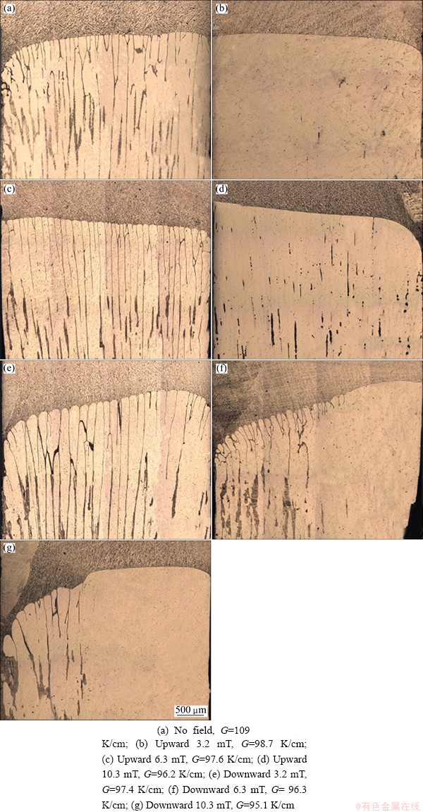
Fig. 1 Solid-liquid interface morphologies of Sn-0.65%Cd alloy in 4 mm-diameter sample at pulling rate of 4 ��m/s
It is well-known that k is modified as k�� when the flow exists in the melt,
 (2)
(2)
where k�� and �� are the effective partition coefficient and the boundary layer thickness, respectively. Thus, Eq. (1) can be modified as [13]
 (3)
(3)
According to thermodynamics theory, the chemical potentials of solute element A is described as
 (4)
(4)
 (5)
(5)
where �� is the chemical potential of the pure A ( =
= ); S is the entropy; ��T is the difference between melting temperature of pure A (Tm) and the actual temperature T; R is the gas constant; x is the solute mole fraction [14]. In the case of the flow, it is considered that
  and
and  are modified as
  and
and  , respectively. At the two-phase equilibrium, we can set Eq. (4) equal to Eq. (5), the following equation is obtained:
 (6)
(6)
where  is the latent heat of pure A. In dilute solution (Sn-0.65%Cd), T �� Tm (melting point of pure A) is supposed. Thus, we obtain
 (7)
(7)
where  and
and  are the modified slopes of liquidus and solidus, respectively. According to
 and Eq. (2), we have

 (8)
(8)
Therefore, Eq. (3) can be further modified as
 (9)
(9)
We assume that M is equal to  , and N is equal to
  . That is, the right part of Eq. (9) is simplified as M/N. According to qualitative analysis, M and N increase simultaneously by the different amount with increasing boundary layer thickness ��. It is predicted that M/N should be a nonlinear function of the boundary layer thickness ��. A preliminary analysis is supposed to present the change of M/N to explain the variety of interface morphologies.
The similar growth condition was simulated by the finite volume software FLUENT in Ref. [3]. The results showed that the flow velocity firstly decreases and then increases with increasing magnetic flux density (B��10.3 mT) under an upward TMF at the interface front, and the flow velocity will decrease with increasing magnetic flux density (B��10.3 mT) under a downward TMF. Generally, the boundary layer thickness �� increases when the flow velocity at the interface front deceases.
In the case of an upward TMF, the boundary layer thickness �� firstly increases and then decreases with increasing magnetic flux density (B��10.3 mT). The value of M/N can change by sine wave, as shown in Fig. 2(a). It is necessary to explain that GL/v appears to be laid in a range because of the small variation of GL under different TMF. The magnetic flux densities of 0, 3.2, 6.3 and 10.3 mT are laid in the regions A, B, C and D in Fig. 2(a), respectively. The cellular interface appears in regions A and C, and the planar interface occurs in regions B and D. Therefore, the planar and cellular interface morphologies change alternately under an upward TMF (B��10.3 mT).
In the case of a downward TMF, the boundary layer thickness �� increases gradually with increasing magnetic flux density (B��10.3 mT). The value of M/N may change in an uncertain pattern, as shown in Fig. 2(b). The magnetic flux densities of 0, 3.2, 6.3 and 10.3 mT are induced in regions A, B, C and D in Fig. 2(b), respectively. The shallow cellular interface appears in the region A, and the deep cellular occurs in region B. The planar interface will form in regions C and D. Consequently, the interface morphology is cellular under a weak downward TMF, and it roughly tends to be planar under a strong downward TMF (B��10.3 mT).
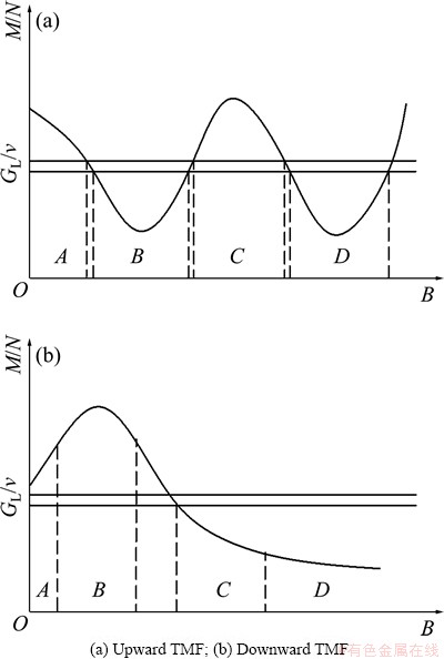
Fig. 2 Sketches of change of M/N with increasing magnetic flux density
However, the morphologies on two sides of the interface become slightly inconsistent. One side of the interface is cellular and the other side is planar, which may be attributed to the damping flow under a downward TMF. It was reported that the flow driven by the downward TMF counteracts nature convection [3], and the damping flow leads to the interface deflection and solute segregation [8]. Under a downward TMF, the damping flow can hinder heat and mass transfer near the interface, which may cause the fluctuation of the temperature and concentration in the interface. The fluctuation of the temperature and concentration results in the inconsistent morphologies on two sides of the interface, and the interface deflection and solute segregation (Fig. 3) become large. The inconsistent morphologies on two sides of the interface and the bigger segregation may also be attributed to the competition between Buoyancy and Lorentz force. According to the distribution of Lorentz force field induced by a TMF, the Lorentz force increases radially from the center to the rim of the TMF generator, and the Lorentz force is tiny at the center of the TMF generator. Consequently, the Lorentz force is very small in a small diameter sample (4 mm) in the present experiment, and the size of the Buoyancy and Lorentz force may be of the same order of magnitude, which may lead to a complex flow. When Buoyancy is dominant, it tends to break the axisymmetric nature of the flow pattern near the interface in the experiment, as reported by NOEPPEL et al [15].
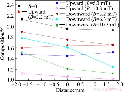
Fig. 3 Radial solute distribution under different TMF near interface by EDS area-scanning
Moreover, this result shows that an upward TMF is helpful to the flattening of interface in this experiment, while an upward TMF appears to be not beneficial to the flattening of interface [8-12]. This should be attributed to the different flow pattern without magnetic field. The flow pattern is upward near the wall in Sn-0.65%Cd alloy, and the interface is always slightly convex, as shown in Fig. 4(a), which is similar to the nature convection pattern in Al-3.5%Ni [2] and Al-4.5%Cu [16], because the rejected solute is heavier than the solvent in these alloys. However, the interface appears to be slightly concave in the crystal growth of semiconductors without magnetic field [8-12], and the corresponding flow pattern is converse to it at the convex interface frontier, as shown in Fig. 4(b). The different flow pattern at the interface frontier may lead to a big discrepancy between the previous study [8-12] and the present one.
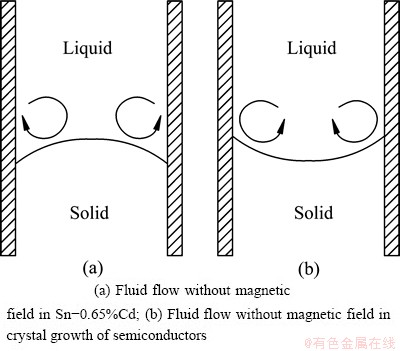
Fig. 4 Sketches of fluid flow
5 Conclusions
1) Planar and cellular interface morphologies transform alternately with increasing magnetic flux density (B��10.3 mT) under an upward TMF.
2) Under a downward TMF, the transformation of interface morphology is shallow cellular �� deep cellular with the application of a weak TMF, and it roughly trends to be planar when the magnetic flux density increases further (B��10.3 mT).
3) An upward TMF appears to be beneficial to flattening the interface for Sn-0.65%Cd alloy.
References
[1] RUDOLPH P. Travelling magnetic fields applied to bulk crystal growth from the melt: The step from basic research to industrial scale [J]. J Cryst Growth, 2008, 310(7-9): 1298-1306.
[2] ZAIDAT K, MANGELINCK-NOEL N, MOREAU R. Control of melt convection by a travelling magnetic field during the directional solidification of Al-Ni alloys [J]. CR Mecanique, 2007, 335(5-6): 330-335.
[3] WANG Lei, SHEN Jun, QIN Ling, FENG Zhou-rong, WANG Ling-shui, FU Heng-zhi. The effect of the flow driven by a travelling magnetic field on solidification structure of Sn-Cd peritectic alloys [J]. J Cryst Growth, 2012, 356: 26-32.
[4] MIN Zhi-xian, SHEN Jun, FENG Zhou-rong, WANG Ling-shui, WANG Lei, FU Heng-zhi. Effects of melt flow on the primary dendrite spacing of Pb-Sn binary alloy during directional solidification [J]. J Cryst Growth, 2011, 320(1): 41-45.
[5] MIN Zhi-xian, SHEN Jun, WANG Ling-shui, LIU Lin. Effect of traveling magnetic field on dendrite growth of Pb-Sn alloy during directional solidification [J]. Transactions of Nonferrous Metals Society of China, 2011, 21(9): 1976-1980.
[6] SU Yan-qing, XU Yan-jin, ZHAO Lei, GUO Jing-jie, FU Heng-zhi. Effect of electromagnetic force on melt induced by traveling magnetic field [J]. Transactions of Nonferrous Metals Society of China, 2010, 20(4): 662-667.
[7] XU Yan-jin, SU Yan-qing, LUO Liang-shun, LI Xin-zhong, LIU Jiang-ping, GUO Jing-jie, CHEN Rui-run, FU Heng-zhi. Effect of traveling magnetic field on gas porosity during solidification [J]. Transactions of Nonferrous Metals Society of China, 2011, 21(9): 1981-1985.
[8] LYUBIMOVA T P, CROELL A, DOLD P, KHLYBOV O A, FAYZRAKHMANOVA I S. Time-dependent magnetic field influence on GaAs crystal growth by vertical Bridgman method [J]. J Cryst Growth, 2004, 266(1-3): 404-410.
[9] SCHWESIG P, HAINKE M, FRIEDRICH J, MUELLER G. Comparative numerical study of the effects of rotating and travelling magnetic fields on the interface shape and thermal stress in the VGF growth of InP crystals [J]. J Cryst Growth, 2004, 266(1-3): 224-228.
[10] ROTSCH C F, JOCKEL D, ZIEM M, RUDOLPH P. Numerical optimization of the interface shape at the VGF growth of semiconductor crystals in a traveling magnetic field [J]. J Cryst Growth, 2008, 310(7-9): 1505-1510.
[11] LANTZSCH R, GRANTS I, PATZOLD O, STELTER M, GERBETH G. Vertical gradient freeze growth with external magnetic fields [J]. J Cryst Growth, 2008, 310(7-9): 1518-1522.
[12] SOCOLIUC V, VIZMAN D, FISCHER B, FRIEDRICH J, MULLER G. 3D numerical simulation of Rayleigh-Benard convection in an electrically conducting melt acted on by a travelling magnetic field [J]. Magnetohydrodynamics, 2003, 39(2): 187-200.
[13] MIN Nai-ben. Physical basis of crystal growth [M]. Shanghai: Shanghai Science and Technology Press, 1982: 206. (in Chinese)
[14] HU Han-qi. Fundamentals of metal solidification [M]. 2nd ed. Beijing: China Machine Press, 2000: 70. (in Chinese)
[15] NOEPPEL A, CIOBANAS A, WANG X D, ZAIDAT K, MANGELINCK N, BUDENKOVA O, WEISS A, ZIMMERMANN G, FAUTRELLE Y. Influence of forced/natural convection on segregation during the directional solidification of Al-based binary alloys [J]. Metall Mater Trans B, 2010, 41(1): 193-208.
[16] LI Xi, FAUTRELLE Y, REN Zhong-ming. Influence of thermoelectric effects on the solid�Cliquid interface shape and cellular morphology in the mushy zone during the directional solidification of Al-Cu alloys under a magnetic field [J]. Acta Mater, 2007, 55(11): 3803-3813.
�в��ų��Զ�������Sn-Cd�Ͻ������ò��Ӱ��
�� �ף��� ��������ˮ�������٣�����־
������ҵ��ѧ ���̼��������ص�ʵ���ң����� 710072
ժ Ҫ����ֱ��Ϊ4 mm��Sn-0.65%Cd�Ͻ����в��ų��н��ж������̣���������������ò�Ƿḻ�����ġ������ϵ��в��ų��ϣ����Ŵų�ǿ�ȵ�����(B��10.3 mT)��ƽ����Ͱ�״���潻��ת�䡣���������µ���ǿ�ȵ��в��ų�(B=3.2 mT)ʱ��������ò��dz��״�����״ת�䡣���ų�ǿ�Ƚ�һ������ʱ����������������IJ�һ�£�������ǿ�Ĵų��½�����ò����������ƽ����(B��10.3 mT)�����ֽ���IJ��ȶ��Կ��ܹ������в��ų����������������⣬�����ϵ��в��ų��н�����״������ˮƽ�ģ����������µ��в��ų��н�����״����б�ġ�
�ؼ��ʣ��������̣��в��ų���������ò��Sn-Cd�Ͻ�
(Edited by Hua YANG)
Foundation item: Project (50774061) supported by the National Natural Science Foundation of China; Project (28-TP-2009) supported by the Research Fund of State Key Laboratory of Solidification Processing (NWPU), China
Corresponding author: Jun SHEN; Tel: +86-29-88494708; Fax: +86-29-88494080; E-mail: shenjun@nwpu.edu.cn
DOI: 10.1016/S1003-6326(13)62754-5

