Al 6013/Mg����Ħ�����ӵIJ������������
��Դ�ڿ����й���ɫ����ѧ��(Ӣ�İ�)2013���5��
�������ߣ�Pooya POURAHMAD Mehrdad ABBASI
����ҳ�룺1253 - 1261
�ؼ��ʣ����ֺ��ӣ�����Ħ���������棻���������������仯�����ѧ���ܣ�6013���Ͻ�þ��
Key words��dissimilar welding; friction stir welding; interface; material flow; intermetallic compounds; mechanical properties; aluminum 6013; magnesium
ժ Ҫ���о�����Ħ���������Ͻ�6013�ʹ�þ���ڽ�ͷ���洦�IJ�����������䡣�����Ͻ�6013�ʹ�þ��ֱ�����ں����ǰ����ͷ��ز࣬��������ں�������ƫ�����Ͻ��1 mm�������Ի����ȱ�ݵĺ��졣Ϊ���о�����Ħ����ʱ�������������������Ƕ�뺸�Ӳ�������Ϊʾ�ٲ��ϣ�������ɺ���X���߷��������ڲ����е�λ�á����������Ƕ��ǰ��������еĸ��躸������˷��ز�����У���Ƕ�ڷ��ز�����еĸ��������ڷ��ز��С��Ժ������������ȴ������о��ȴ����Ժ��ӽ�ͷ��ѧ���ܵ�Ӱ��ͽ�ͷ�������仯�������������������������ڽ�ͷ���洦������2�ֽ����仯���Al3Mg2��Al12Mg17��
Abstract: Material flow and phase transformation were studied at the interface of dissimilar joint between Al 6013 and Mg, produced by stir friction welding (FSW) experiments. Defect-free weld was obtained when aluminum and magnesium were placed in the advancing side and retreating side respectively and the tool was placed 1 mm off the weld centerline into the aluminum side. In order to understand the material flow during FSW, steel shots were implanted as indexes into the welding path. After welding, using X-ray images, secondary positions of the steel shots were evaluated. It was revealed that steel shots implanted in advancing side were penetrated from the advancing side into the retreating side, whereas the shots implanted in the retreating side remained in the retreating side, without penetrating into the advancing side. The welded specimens were also heat treated. The effects of heat treatment on the mechanical properties of the welds and the formation of new intermetallic layers were investigated. Two intermetallic compounds, Al3Mg2 and Al12Mg17, were formed sequentially at Al6013/Mg interface.
Trans. Nonferrous Met. Soc. China 23(2013) 1253-1261
Pooya POURAHMAD, Mehrdad ABBASI
Department of Materials Science and Engineering, Islamic Azad University, Karaj Branch, Karaj, Iran
Received 9 May 2012; accepted 20 September 2012
Abstract: Material flow and phase transformation were studied at the interface of dissimilar joint between Al 6013 and Mg, produced by stir friction welding (FSW) experiments. Defect-free weld was obtained when aluminum and magnesium were placed in the advancing side and retreating side respectively and the tool was placed 1 mm off the weld centerline into the aluminum side. In order to understand the material flow during FSW, steel shots were implanted as indexes into the welding path. After welding, using X-ray images, secondary positions of the steel shots were evaluated. It was revealed that steel shots implanted in advancing side were penetrated from the advancing side into the retreating side, whereas the shots implanted in the retreating side remained in the retreating side, without penetrating into the advancing side. The welded specimens were also heat treated. The effects of heat treatment on the mechanical properties of the welds and the formation of new intermetallic layers were investigated. Two intermetallic compounds, Al3Mg2 and Al12Mg17, were formed sequentially at Al6013/Mg interface.
Key words: dissimilar welding; friction stir welding; interface; material flow; intermetallic compounds; mechanical properties; aluminum 6013; magnesium
1 Introduction
Joined parts, made of aluminum and magnesium, are widely used in automotive, aerospace and other industries, where the combination of high strength and weight reduction is the main concern. Problems such as cracking, expulsion and void in the weld zone made joining of magnesium to aluminum alloys very difficult using conventional techniques. As CHEN and NAKATA [1] reported, a variety of attempts to weld these alloys using fusion welding technology led to a failure. These investigations showed that this technique was not suitable due to the formation of intermetallic compounds in the weld, which was deleterious to the mechanical properties. Therefore, friction stir welding (FSW) can be considered as a solution for these kinds of welding.
ATTALLAH and SALEM [2] and SAUVAGE et al [3] showed that defect-free welds with good mechanical properties can be made in a wide variety of aluminum alloys. Also, ABBASI GHARACHEH et al [4], AFRIN et al [5], and CAO and JAHAZI [6] achieved successful FSW joints for different magnesium alloys. Stir friction dissimilar welding between aluminum and magnesium has recently received much attention. YAN et al [7] investigated the friction stir weld ability of Mg alloy AZ31 to Al alloy 1060. As they reported, visually sound welds could be produced. However, the formation of a thin intermetallic layer at the interface would result in the welds exhibiting virtually no ductility. The intermetallic layers were identified as Al3Mg2 and Al12Mg17. Also KOSTKA et al [8] found that during friction stir welding of AZ31 to AA6040, two intermetallic phases were formed in the intermediate layer. Further studies revealed that these intermetallic compounds consisted of Al3Mg2 and Al12Mg17. FIROUZDOR and KOU [9,10] focused on the FSW of 6061 aluminum to AZ3. Their studies showed that placing materials in different sides of the weld contributed to different consequences. Also they reported that macroscopic intermetallics could be formed during FSW, which is a direct conclusion of melting in the interface of the weld.
In this study, the metallurgical parameters of friction stir welding of 6013 aluminum and pure magnesium were studied in order to provide more information for the practical friction stir welding of Al-Mg joints. The influences of heat treatment on intermetallic layers and mechanical properties of friction stir welded joints are also investigated.
2 Experimental
Aluminum 6013 and pure magnesium plates were welded by friction stir welding process. Specifications of the materials are summarized in Table 1. The weld has two sides relative to the centerline. One is referred to the advancing side (AS), where the rotational motion and linear motion of the pin are in the same direction. The other is the retreating side (RS), where the rotational motion and linear motion of the pin are in the opposite directions. YAN et al [7], KOSTKA et al [8], and KWON et al [11] reported that the best metallurgical quality for Al to Mg FSW joints can be achieved if aluminum and magnesium were placed in the advancing side and the retreating side, respectively. Considering these results, in this study, the magnesium plate was located on the retreating side and the aluminum plate was located on the advancing side. The initial dimensions of the plates were rectangular, 100 mm��100 mm��10 mm. FSW tool was made of H13 tool steel heat treated at 900 ��C for 1 h, and quenched in oil. The shoulder diameter of the tool was 20 mm. The pin of the tool had a conic shape (with the maximum diameter of 6 mm and the minimum diameter of 4 mm) and a height of 6 mm. In order to optimize the welding parameters, various tool rotation speeds from 800 to 2000 r/min, traverse speeds from 31 to 75 mm/min and an offset tool angle of 2�� and 3�� were applied. Experiments were performed first when the stirring pin was placed 1 mm off the centerline to the aluminum advancing side. Second, the stirring pin was placed exactly at the centerline and finally it was placed 1 mm off the centerline into the magnesium retreating side. Also, a copper block, as the heat sink, was placed under the joint assembly to prevent excessive heating during all of the tests.
Table 1 Chemical composition and mechanical properties of experimental materials

To investigate the material flow around the FSW tool, steel shots with a diameter of 1 mm were embedded firstly 1 mm into the advancing side and secondly 1 mm into the retreating side. In both tests welding was performed using optimized parameters. Then, X-ray images were taken from the welded joints to detect the secondary position of the steel shots. Distribution of the steel shots at different heights from the faying surface clarified the material flow from the face to root of the weld.
In order to study the effects of heat treatment on intermetallic phases and mechanical properties of the FSW joints, the specimens were heated to 320 ��C and held for 1, 2 and 4 h, respectively. Then, they were quenched in still air at room temperature. The mechanical properties of the joint were measured using tensile tests. The FSW joints were cross-sectioned perpendicular to the welding direction and then machined into rectangular specimen with dimensions of 200 mm��20 mm��6 mm for the tensile tests, whereas the weld zone was placed in the middle of the specimens and the welding has formed throughout the thickness. The metallurgical microstructures of the dissimilar weld interface were analyzed by scanning electron microscopy (SEM) equipped with an energy-dispersive X-ray spectroscopy (EDS) analysis system.
3 Results and discussion
3.1 Optimizing welding parameters
Welding of 6013 aluminum and pure magnesium was carried out only when placing the rotating pin 1 mm off the centerline into the aluminum advancing side. Inserting the pin into the centerline caused a process more like a milling process in which no welding could be reached. Also, inserting the pin 1 mm off the centerline into magnesium resulted in defected weld due to the melting of magnesium, and line defects were observed along the weld line. Attaining a good welding quality was possible when no melting occurred throughout the weld line. Aluminum required more heat input to become plastic, due to its higher heat conductivity (250 W/(m����C)), than that of Mg (156 W/(m����C)). Therefore, inserting the pin into the aluminum side caused the concentration of frictional heat in the aluminum side. MISHRA and MA [12] presented a series of equations for the FSW of aluminum alloys. Similarly, Eq. (1) determinates the principle correlation between the welding parameters and the heat generation in the FSW, in which the rotational speed (��) has direct effect on the heat input and linear speed (v) has the reverse effect on the heat input.
 (1)
(1)
To attain a sound weld by FSW between two dissimilar metals, it is better to insert the tool pin in the material with higher heat capacity and higher plasticity. Figure 1 shows the appearances of the FSW joints with different parameters of welding. A rotation speed of 1250 r/min, welding speed of 50 mm/min and tilt angle of 2�� caused a void throughout the weld line (Fig. 1(a)). This defect is likely to occur due to the poor stirring action and the low heat input. Increasing the rotation and welding speed up to 1600 r/min and 70 mm/min increased the size of the void. On the contrary, the surface morphology of the weld became smoother (Fig. 1(b)). In Fig. 1(c), heat generation increased due to the decrease of the linear welding speed. Consequently, the void became much smaller. Sound weld was obtained when the tilt angle of the weld was changed to 3�� with the rotation speed of 1600 r/min and the welding speed of 35 mm/min. This suggested that, 3�� of tilt angle of the pin improved the stirring action of the pin and caused more penetration force for the extrusion of Al into Mg. Changing the tilt angle helped the shoulder of the tool to push the stirred material from the front to the rear of the pin. Further reduction of the welding speed and increase of the rotation speed led to excessive heat generation which caused the weld metal to melt.
3.2 Material flow patterns
Figure 2(a) presents the original position of the steel shots planted in the aluminum advancing side. The X-ray image (Fig. 2(b)) taken after FSW of the same plate showed the secondary position of the shots. Consideration of the secondary position of steel shots showed that, from the surface to the depth of 6 mm of the weld, shots were exposed to the stirring action of the pin. As a result, the steel shots were moved about 1.5-2 mm into the retreating side and pushed back for about one diameter of the pin. The black arrow in Fig. 2 shows the movement of shot No. 2. Secondary position of the steel shots also proved that, there was no material flow below the pin and the root of joints. For example, since the steel shot No.1 was planted in the depth of 7 mm and the material was not stirred, the steel shot did not move. This suggested that to obtain a complete penetrated weld throughout the thickness of the plate, the pin height and the thickness of the plates should be nearly the same.
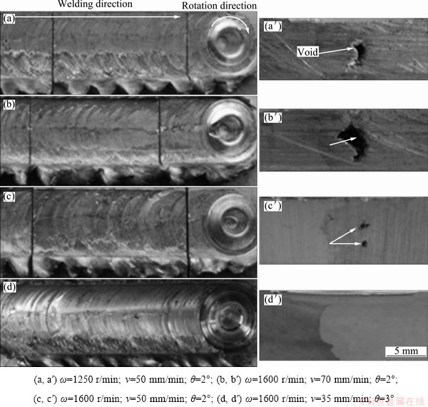
Fig. 1 Appearances of welds surface (a, b, c, d) and welds cross section (a��, b��, c��, d��) perpendicular to weld line
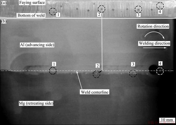
Fig. 2 (a) Initial place of steel shots planted into aluminum advancing side; (b) X-ray image after FSW showing secondary position of steel shots
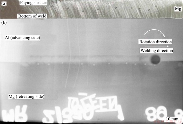
Fig. 3 (a) Initial place of steel shots planted into magnesium retreating side; (b) X-ray image after FSW showing secondary position of steel shots
Figure 3(a) shows the original position of the steel shots in the magnesium retreating side. Figure 3(b) also shows the X-ray image taken after FSW of the same plate that contained steel shots. In contrast with Fig. 2, steel shots remained in the retreating side; in this case, steel shots were moved for about 1.5-2 mm into the retreating and pushed back for about one diameter of the pin. The amount of this movement depended on the original places of the shots.
Figure 4 illustrates the difference between the movements of the steel shots in advancing and retreating sides separately. Steel shots in the advancing side moved through plasticized materials, turning �� degree into the retreating side and stored behind the pin. On the contrary, the steel shots in the retreating side tended to remain in the retreating side and was only pushed back with the movement of �� degree and stored behind the pin. Figure 5 shows a cross section of FSW joint. Interface macrograph of the welded specimens showed that, three different regions can be recognized in the interface regarding the depth of the region from the surface of the weld. The first region is the upper part, near the surface of the weld, where plastic deformation and material flow were strengthened due to the shoulder effect. It can be seen that aluminum was extensively extruded into magnesium and a rough and zigzag interface formed.

Fig. 4 Movement of steel shot during FSW

Fig. 5 (a) Cross section of weld showing different regions of interface; (b) Islanding and interlocking in upper part of weld
Likewise, interlocking was evident in the upper part of the weld due to the direct effect of the intensive plastic deformation and extrusion at the top of the weld. Islanding and interlocking were observed only in the upper part of the weld. The separation of the aluminum island in the magnesium side is shown as area No. 1 in Fig. 5(b), and the magnesium island in the aluminum side is shown as area No. 2 in Fig. 5(b). On the contrary, in the middle of the weld or the second region, the interface became smoother and the extrusion of aluminum into magnesium was less. The third region is near the end of the pin in which the extrusion of aluminum into magnesium was the least. Some differences of the extrusion and mixture of the materials in different regions are the consequence of diverse material flow and different penetration forces.
3.3 Microstructure observation of Al/Mg interface
The formation of the intermetallic phases in the as-welded and the heat treated specimens was studied using FSWed joints fabricated with the optimized parameters. SEM and EDS analyses were done in order to study the intermetallic compounds formed in the Al/Mg interface during the friction stir welding process. Figure 6 illustrates EDS analysis from an upper region and central region of the Al/Mg interface. From EDS line analysis and SEM image (Fig. 6(b)), it is evident that there was no intermetallic layer formed in the middle of the Al/Mg interface. On the contrary, it is revealed that in the upper part of the Al/Mg interface (Fig. 6(a)), continuous layer of intermetallic compound was formed at the weld interface.

Fig. 6 SEM and EDS analysis of as-welded FSW joints
According to the EDS quantitative analysis, the composition of the intermetallic layer is defined to be Al3Mg2 or �� phase (x(Al)=57.93%, x(Mg)=42.07%). The appearance of the intermetallic layer with a thickness of 2 ��m in the upper part of the interface can be attributed to the more heat input on the surface of the weld, which was generated by the friction effect of the shoulder. MORISHIGE et al [13] studied the fractography of an FSW joint of Al-Mg system. Similarly, they reported that the intermetallic phase was present in the upper part of the weld zone.
3.4 Effects of heat treatment on intermetallic layer in Al/Mg interface
MISHRA and MA [12] showed that, a huge amount of residual stress would remain in the weld zone as a result of stirring action and plastic deformation during the FSW process. This residual stress has a deleterious effect on the mechanical properties of the weld. In order to enhance the metallurgical properties and release the residual stress, post weld heat treatment was performed on the welded plates. The FSW joints were heat treated for 1, 2 and 4 h, respectively. In order to prevent melting in the interface, the heat treatment temperature was chosen to be 320 ��C due to the eutectic reactions at 437 and 450 ��C in the binary phase diagram of Al-Mg system [14]. Figure 7 illustrates the SEM image accompanied by the EDS line and quantitative analysis of Al/Mg interface after 1 h of heat treatment. The EDS line scan of the Al/Mg interface suggested that after 1 h of heat treatment, the thickness of the intermetallic layer was slightly increased to about 4 ��m. Quantitative analysis also revealed that the intermetallic layer would be Al3Mg2 or �� phase (x(Al)=58.51%, x(Mg)=41.49%) .

Fig. 7 EDS line and quantitative analysis of Al/Mg interface for FSW joint after heat treatment for 1 h at 320 ��C
From Fig. 8(a), it was observed that after 2 h of heat treatment, the intermetallic layer was thickened to about 12 ��m. Quantitative analysis showed that the intermetallic layer is �� phase with the composition of x(Al)=63.92% and x(Mg)=36.08%. Also in the EDS mapping analysis of the interface, the intermetallic layer was evident by the white arrow No. 1. FIROUZDOR and KOU [10] reported the presence of this thick intermetallic layer in the as-welded specimen. They stated that in the limited time of the FSW process, solid state diffusion was very low, therefore the presence of thick intermetallic layers was attributed to the solidification of the liquated material in the interface. Similarly, CHEN and NAKATA [1] reported that the layer of intermetallic compounds can be formed in the middle of the FSW lap joints as a result of melting during the welding. They stated that these intermetallics had solidified microstructure; however, in this study, the growth of intermetallic layer was due to the heat treatment and there was no sign of solidified microstructure in the interface.
Figure 9 shows that after 4 h of heat treatment, intermetallic layer in Al/Mg interface developed even more. Unlike other samples, the intermetallic layer in the interface consisted of two different compositons which could be detected by the quantitative analysis. Layer No. 1 was determined as Al12Mg17 or g phase (x(Al)=43.24%, x(Mg)= 56.76%), whereas the layer No. 2 was Al3Mg2 or �� phase (x(Al)=63.93%, x(Mg)=36.07%). It can be concluded that heat treatment of the FSW joints of aluminum and magnesium caused the growth of the intermetallic component in the Al/Mg interface and the overall thickness of the intemetallic layers was about 23 ��m.
Figure 10 shows a higher magnification SEM image taken from the 4 h-heat treated specimen. Al3Mg2 was always formed near the aluminum and Al12Mg17 was formed near magnesium. Al12Mg17 was the white etched texture and the dark pits were Mg-rich area.
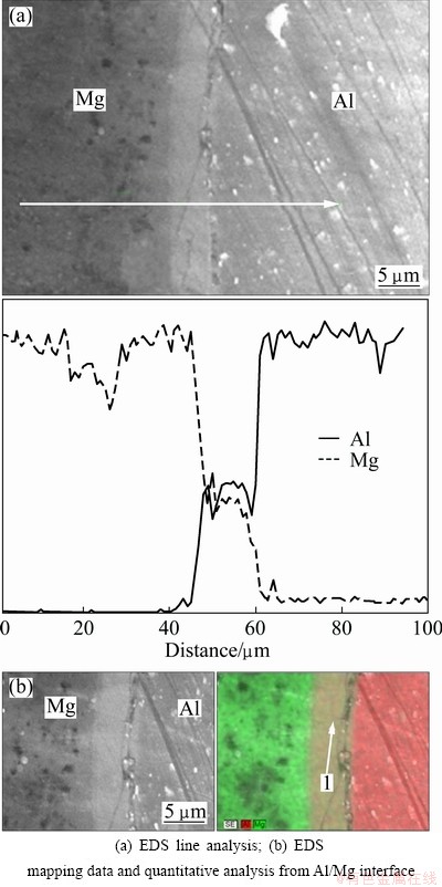
Fig. 8 SEM and EDS analysis of FSW joints after heat treatment for 2 h at 320 ��C
3.5 Effects of heat treatment on mechanical properties
Figure 11 shows the results of tensile tests for the as-welded and heat treated specimens. Tensile strength and elongation of the as-welded specimen were 20.62 MPa and 3.7%, respectively. Low tensile strength in this specimen could be attributed to the formation of a brittle layer of �� phase at the interface and residual stress [13]. After 1 h of heat treatment at 320 ��C, the tensile strength and elongation were improved up to 36.14 MPa and 4.5%, respectively. �� phase was thickened to about 4 ��m after 1 h heat treatment. Post weld heat treatment of dissimilar metals would lead to a new set of residual stresses due to different thermal expansion coefficients of aluminum and magnesium. But in this study, the tensile strength was improved after heat treatment. Since the difference between the thermal expansion coefficients of aluminum and magnesium is not much, the increase of tensile strength could be attributed to the effect of more stress relief than the generation of new stress in 1 h heat treatment. A 2 h heat treatment led to a decrease in the tensile strength and elongation to 32.62 MPa and 4%, respectively. This reduction of mechanical properties could be due to the growth of �� phase to about 12 ��m. A 4 h heat treatment caused a decrease in tensile strength and elongation to 20.28 MPa and 2.5%, respectively. This is due to the excessive growth of �� phase and the formation of new g phase between Mg and �� phase. The overall thickness of these layers reached up to 23 ��m. This excessive growth of brittle intermetallic layers would cause the join strength to decrease.

Fig. 9 EDS line and quantitative analysis of Al/Mg interface for FSW joint after 4 h of heat treatment at 320 ��C
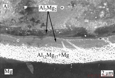
Fig. 10 SEM image of Al/Mg interface in FSW joint after 4 h of heat treatment at 320 ��C

Fig. 11 Tensile strength and elongation of as-welded and heat treated specimens
The tensile strength of gas tungsten arc welded joints of 1060/AZ31 without filler metal is nearly zero [7]; comparatively, the maximum tensile strength for FSW of Al 6013 to pure magnesium was 36.14 MPa in this study.
Figure 12 shows the location of fracture in the tensile specimens. For all specimens, the fracture took place along the Al�CMg interface same as that in Fig. 12. SEM analysis (Figs. 6 and 7) verified that the formation of intermetallic compounds took place exactly in the same area that the fracture would happen. The location of fracture suggested that the main reason of the failure was the formation of intermetallic compounds in the Al/Mg interface. Similarly, MORISHIGE et al [13] reported that all the tensile samples ruptured at the interface whereas the fracture surface has cracked at intermetallic phase.
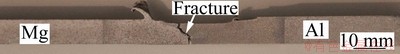
Fig. 12 Fracture location in tensile specimen
4 Conclusions
1) Defect-free welds were successfully achieved when the tool rotation speed was 1600 r/min, the traverse speed was 35 mm/min and the tilt angel was 3��. Welds were made only when the stirring pin was 1 mm off the centerline towards aluminum side.
2) From X-ray images, it was observed that material flow or displacement of the implanted steel shots in the advancing side was bigger than that in the retreating side.
3) Micrographs of cross section of dissimilar welds revealed three regions. The first upper region experienced extensive extrusion and stirring action where zigzag interface, interlocking and islanding were observed. The second middle region experienced less extrusion of aluminum into magnesium than the upper portion where the weld interface was smoother. The third bottom region is around the weld root and the extrusion of aluminum into magnesium was the least.
4) In as-welded specimen, a 2 ��m thickness layer of Al3Mg2 or �� phase was formed in the upper region of the weld. This is due to the higher temperature and extrusion effect imposed by the shoulder at upper region.
5) The thickness of intermetallic Al3Mg2 (�� phase) layer was about 4 ��m and 12 ��m after heat treatment of 1 h and 2 h, respectively. After 4 h of heat treatment, a new intermetallic layer was formed between Mg and �� layer. The composition of the new layer was detected to be Al12Mg17 and the total thickness of g and �� intermetallic layers were about 23 ��m.
6) The tensile strength increased after 1 h heat treatment. This was due to the more stress relief than the generation of new termal expansion stress. By extending heat treatment time to 2 and 4 h, the tensile strenght and elongation of the welds were decreased. This may be due to the increase of thickness of �� phase and the formation of new g intermetallic brittle phases.
References
[1] CHEN Y C, NAKATA K. Friction stir lap joining aluminum and magnesium alloys [J]. Scripta Materialia, 2008, 58(1): 433-436.
[2] ATTALLAH M M, SALEM H G. Friction stir welding parameters: A tool for controlling abnormal grain growth during subsequent heat treatment [J]. Materials Science and Engineering A, 2005, 391(1-2): 51-59.
[3] SAUVAGE X, DEDE A, CABELLO MUNOZ A, HUNEAU B. Precipitate stability and recrystallization in the weld nuggets of friction stir welded Al�CMg�CSi and Al�CMg�CSc alloys [J]. Materials Science and Engineering A, 2008, 491(1-2): 364-371.
[4] ABBASI GHARACHEH M, KOKABI A H, DANESHI G H, SHALCHI B, SARRAFI R. The influence of the ratio of ����rotational speed/traverse speed���� on mechanical properties of AZ31 friction stir welds [J]. Machine Tools & Manufacture, 2006, 46(15): 1983-1987.
[5] AFRIN N, CHEN D L, CAO X, JAHAZI M. Microstructure and tensile properties of friction stir welded AZ31B magnesium alloy [J]. Materials Science and Engineering A, 2008, 472(1-2): 179-186.
[6] CAO X, JAHAZI M. Effect of welding speed on the quality of friction stir welded butt joints of a magnesium alloy [J]. Materials and Design, 2009, 30(6): 2033-2042.
[7] YAN Jiu-chun, XU Zhi-wu, LI Zhi-yuan, LI Lei, YANG Shi-qin. Microstructure characteristics and performance of dissimilar welds between magnesium alloy and aluminum formed by friction stirring [J]. Scripta Materialia, 2005, 53(5): 585-589.
[8] KOSTKA A, COELHO R S, DOS SANTOS J, PYZALLAC A R. Microstructure of friction stir welding of aluminum alloy to magnesium alloy [J]. Scripta Materialia, 2009, 60(11): 953-956.
[9] FIROUZDOR V, KOU A. Al-to-Mg friction stir welding: Effect of material position, travel speed, and rotation speed [J]. Metallurgical and Materials Transactions A, 2010, 41(11): 2914-2935.
[10] FIROUZDOR V, KOU A. Formation of liquid and intermetallics in Al-to-Mg friction stir welding [J]. Metallurgical and Materials Transactions A, 2010, 41(12): 3238-3251.
[11] KWON Y J, SHIGEMATSU I, SAITO N. Dissimilar friction stir welding between magnesium and aluminum alloys [J]. Materials Letters, 2008, 62(23): 3827-3829.
[12] MISHRA R S, MA Z Y. Friction stir welding and processing [J]. Materials Science and Engineering R, 2005, 50(1-2): 1-78.
[13] MORISHIGE T, KAWAGUCHI A, TSUJIKAWA1 M, HINO M, HIRATA T, HIGASHI K. Dissimilar welding of Al and Mg alloys by FSW [J]. Materials Transactions, 2008, 49(5): 1129-1131.
[14] ASM Handbook. Vol. 3. Binary alloy phase diagram [M]. ASM International, 1992: 48.
Pooya POURAHMAD, Mehrdad ABBASI
Department of Materials Science and Engineering, Islamic Azad University, Karaj Branch , Karaj, Iran
ժ Ҫ���о�����Ħ���������Ͻ�6013�ʹ�þ���ڽ�ͷ���洦�IJ�����������䡣�����Ͻ�6013�ʹ�þ��ֱ�����ں����ǰ����ͷ��ز࣬��������ں�������ƫ�����Ͻ��1 mm�������Ի����ȱ�ݵĺ��졣Ϊ���о�����Ħ����ʱ�������������������Ƕ�뺸�Ӳ�������Ϊʾ�ٲ��ϣ�������ɺ���X���߷��������ڲ����е�λ�á����������Ƕ��ǰ��������еĸ��躸������˷��ز�����У���Ƕ�ڷ��ز�����еĸ��������ڷ��ز��С��Ժ������������ȴ������о��ȴ����Ժ��ӽ�ͷ��ѧ���ܵ�Ӱ��ͽ�ͷ�������仯�������������������������ڽ�ͷ���洦������2�ֽ����仯���Al3Mg2��Al12Mg17��
�ؼ��ʣ����ֺ��ӣ�����Ħ���������棻���������������仯�����ѧ���ܣ�6013���Ͻ�þ��
(Edited by Sai-qian YUAN)
Corresponding author: Mehrdad ABBASI; Tel: +98-261418232; E-mail: mehrdad600@gmail.com
DOI: 10.1016/S1003-6326(13)62590-X

