AZ91��AZ80þ�Ͻ���溬ʯī��������PEOͿ���Ħ����ʴ��Ϊ
��Դ�ڿ����й���ɫ����ѧ��(Ӣ�İ�)2018���2��
�������ߣ�L. PEZZATO V. ANGELINI K. BRUNELLI C. MARTINI M. DABAL��
����ҳ�룺259 - 272
�ؼ��ʣ������ӵ����������ĥ�ԣ���ʴ�ԣ�þ�Ͻ�ʯī������
Key words��plasma electrolytic oxidation; wear resistance; corrosion resistance; magnesium alloy; graphite nanoparticles
ժ Ҫ���õ����ӵ������(PEO)����AZ91 �� AZ80 þ�Ͻ�����Ʊ�Ϳ�㣬�о��ڵ��Һ������ʯī��������Ϳ�����ʴ�Ժ���ĥ���ܵ�Ӱ�졣���õ��ҺΪ���������κ����εļ�����Һ�����������ֲ�ͬ��PEO ����ʱ��(1 min��3 min)���ö���λ�������͵绯ѧ�迹��(EIS)����Ϳ�����ʴ�ԣ���ƽ��-��ʽ����Ħ��ʵ���������ĥ���ܡ���ɨ��羵��������(SEM-EDS)�۲�Ϳ�����֯��ò���۽ṹ��Ԫ����ɺ�Ϳ���ȡ����������ʯī������������Ϳ��ĺ�ȣ�����˱���Ŀ�϶��ʹͿ������ܣ�������������ʴ�Ժ���ĥ���ܡ�����AZ91���и��ߵ�������������ʴ���ܺ���ĥ���ܵ���߱�AZ80��������
Abstract: The effect of the addition of graphite nanoparticles into the electrolyte used to produce plasma electrolytic oxidation (PEO) coatings on AZ91 and AZ80 magnesium alloys was studied. The corrosion and wear resistances of the obtained coatings were investigated. A solution that contained both phosphates and silicates was used as electrolyte. Moreover, two different PEO treatment times were studied. The corrosion resistance was analyzed with potentiodynamic polarization and EIS tests; the wear resistance was investigated with a flat on ring tribometer. The results were related to the morphology, microstructure, elemental composition and thickness evaluated with SEM analysis. The presence of the graphite nanoparticles increased the thickness, produced a densification of the coating and sealed the pores on the surface, thus improving both the corrosion and wear resistance. The increase in the corrosion and wear resistances was more evident for AZ91 than for AZ80 due to the higher aluminum content.
Trans. Nonferrous Met. Soc. China 28(2018) 259-272
L. PEZZATO1, V. ANGELINI2, K. BRUNELLI1, C. MARTINI2, M.  1
1
1. Department of Industrial Engineering, University of Padua, Via Marzolo 9, 35131 Padova, Italy;
2. Department of Industrial Engineering, Alma Mater Studiorum, University of Bologna, V. le Risorgimento 4, 40136 Bologna, Italy
Received 23 January 2017; accepted 1 June 2017
Abstract: The effect of the addition of graphite nanoparticles into the electrolyte used to produce plasma electrolytic oxidation (PEO) coatings on AZ91 and AZ80 magnesium alloys was studied. The corrosion and wear resistances of the obtained coatings were investigated. A solution that contained both phosphates and silicates was used as electrolyte. Moreover, two different PEO treatment times were studied. The corrosion resistance was analyzed with potentiodynamic polarization and EIS tests; the wear resistance was investigated with a flat on ring tribometer. The results were related to the morphology, microstructure, elemental composition and thickness evaluated with SEM analysis. The presence of the graphite nanoparticles increased the thickness, produced a densification of the coating and sealed the pores on the surface, thus improving both the corrosion and wear resistance. The increase in the corrosion and wear resistances was more evident for AZ91 than for AZ80 due to the higher aluminum content.
Key words: plasma electrolytic oxidation; wear resistance; corrosion resistance; magnesium alloy; graphite nanoparticles
1 Introduction
The use of magnesium alloys in engineering applications has increased in the last years due to the attractive combination of low density and high strength specific ratio [1,2]. The main problems that affect these alloys are the corrosion and wear resistances that resulted very low. This behaviour is attributed in literature to the high chemical activity of magnesium and to the unstable imperfect natural oxide film on its surface [3,4].
Plasma electrolytic oxidation (PEO) treatment of metals, derived from traditional anodizing, is a process that induces the formation of an oxide ceramic coating on metal surfaces thanks to the application of high voltages and high current densities [5,6]. The PEO coatings are harder than the magnesium substrate and are characterized by higher wear and corrosion resistance [7]. In fact, PEO coatings are adherent to the substrate and contribute to reducing the wear of magnesium alloys. In particular, the presence of secondary phases into PEO coating can improve the wear resistance of the samples.
However, during dry sliding experiments, it was found that the friction coefficient of PEO coatings is higher than that of the magnesium substrate [8-10]. So, one objective of the scientific research in recent years was the development of composite PEO coatings characterized by higher tribological performance and lower friction coefficient. The addition of additives into the electrolyte induces significant changes in the resistance of the coatings. The introduction of zirconia particles was tested by some authors [11-13] in order to increase the hardness of the coating. More recent researches show that a good way to increase the tribological properties of PEO layers is the reduction of the friction coefficient by the introduction a solid lubricant into the coating. In this case, particles of solid lubricant, such as graphite, polytetrafluoroethylene (PTFE), MoS2, and WS2, are added directly into the electrolyte and dispersed with mechanical stirring or using special additives. During the formation of the PEO coatings the solid lubricant can be incorporated into the oxide ceramic coating. Using this approach some authors produced graphite- or MoS2-containing coatings on aluminum alloys using different types of electrolytes [14-16]. Other authors studied the effect of electric parameters on the embedding of Si3N4 nanoparticles into TiO2 coatings [17,18].
As discussed above, many papers can be found regarding the preparation of self-lubricant PEO coatings on aluminum and titanium alloys, but works regarding magnesium alloys are lacking.
In this work, graphite nanoparticles were added into the PEO electrolyte in order to reduce the wear and friction coefficient of the magnesium alloy. The graphite nanoparticles were preferred to graphite particles because, as reported by LV et al [19], smaller graphite grains could be adsorbed more easily on the coating surface and thus embedded to the coatings. PEO process was performed at high current densities and with short treatment time using AZ91 and AZ80 magnesium alloys as substrates. Moreover, the influence of the addition of graphite nanoparticles on both the corrosion resistance and the microstructure of the obtained samples was evaluated.
2 Experimental
The samples of AZ91 and AZ80 magnesium alloys were used as substrates for PEO coatings. The samples were cut from ingots and, before PEO treatment, were polished by standard metallographic techniques and then degreased in ultra-sonicated acetone. The PEO electrolyte was an aqueous alkaline solution with 50 g/L of Na5P3O10, 50 g/L of Na2SiO3, 40 g/L of NaOH and 3 g/L of graphite nanoparticles. The nanoparticles were dispersed in acetone before their addition to the PEO electrolyte. Samples without the addition of graphite were also produced to compare the results.
A TDK-Lambda DC power supply of 400 V/8 A capacity was used during the plasma electrolytic oxidation process.
A TEM image of the as-supplied graphite nanoparticles (<100 nm) is shown in Fig. 1.
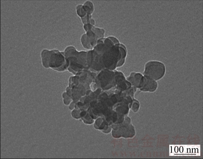
Fig. 1 TEM image of graphite nanoparticles
During the process, the sample of magnesium alloy worked as anode whereas for the cathode a carbon steel mesh was used. The electrolyte was agitated with magnetic stirring and was kept at room temperature using a cooling bath. The treatments were carried out at a constant current density of 0.5 A/cm2 and the voltage variations were measured. Two different treatment times were used: 1 min and 3 min.
The initial and final voltages, achieved during the treatment, were 70 and 100 V, respectively. The PEO coated samples were washed three times with a solution of deionized water and ethanol and then dried with compressed air. The coated samples were cut and the resulting cross-sections were mounted in epoxy resin and polished by standard metallographic techniques. The morphological features, the thickness of the coating and the elemental composition of both the surface and the cross-section of samples were investigated using a Cambridge Stereoscan 440 scanning electron microscope, equipped with a Philips PV9800 EDS.
The analysis of the phases of the coatings was performed using a Siemens D500 X-ray diffractometer with a monochromatic Cu K�� radiation source (��= 0.15405 nm), working at 40 kV and 30 mA.
In order to understand the influence of treatment time and graphite nanoparticles on the mechanical strength of the PEO layers, Vickers micro-hardness (HV0.1) was measured on polished cross section to avoid substrate contributions.
Dry sliding tests were carried out on untreated and PEO-treated samples (5 mm �� 5 mm �� 70 mm) using a flat-on-cylinder tribometer (block-on-ring contact geometry, ASTM G-77 [20]), described in further detail elsewhere [21]. A 100Cr6 (AISI 52100) bearing steel cylinder was used as counter material, with a surface hardness of HRC 60 and a roughness of Ra=0.2 ��m. Sliding tests were performed under conditions of ambient temperature and humidity (relative humidity ranging from 50% to 60%), at a fixed sliding speed of 0.3 m/s, a sliding distance of 500 m, and a normal load of 5 N. Friction force values were continuously recorded during each test as a function of sliding distance, by means of a bending load cell. Friction values were averaged over the steady state regime for each test and then averaged again over the 3 repetitions of each test.
After the tests, wear scar depths and widths on sliders and cylinders were separately evaluated by stylus profilometry (tip radius: 5 ��m). Wear depth values were obtained by averaging at least 3 profiles on each wear scar and then averaging again the mean values of each scar over the 3 repetitions of each test. Worn surfaces and wear debris were observed by Hirox KH 7700 3D-digital microscope and SEM-EDS, in order to identify the dominant wear mechanisms.
Potentiodynamic and electrochemical impedance spectroscopy (EIS) tests were carried out to study the corrosion resistance of the coatings. The potentio- dynamic experiments were performed with an AMEL 2549 potentiostat in a solution containing 0.05 mol/L NaCl and 0.1 mol/L Na2SO4, using as reference electrode, a saturated calomel electrode (SCE) and as counter electrode, a platinum electrode, with a scan rate of 0.5 mV/s. The EIS tests were carried out in the same solution described above, at the value of the open circuit potential and in a frequency range between 1��105 Hz and 1��10-2 Hz, using a perturbation amplitude of 10 mV. The impedance tests were recorded with a Materials Instrument Spectrometer coupled with the 2549 potentiostat and the ZView software was employed for the fitting of impedance spectra.
3 Results and discussion
The samples of AZ91 and AZ80 magnesium alloys, treated at different treatment time, with and without graphite nanoparticles (as described in the experimental section) were characterized, by SEM observation, before corrosion and tribological testing.
3.1 Surface analysis
The SEM images of the cross section and surface of PEO-coated AZ91 samples are shown in Fig. 2 (treatment without graphite nanoparticles) and Fig. 3 (treatment with graphite nanoparticles). Both the treatments, performed for 1 and 3 min, produced a continuous coating, characterized by the typically porous surface of PEO-treated samples. Cross-section SEM images showed good bonding at the interface between the substrate and the coating in all treated samples.
The main difference among the samples was the thickness of the PEO layer, which is summarized in Table 1.
The thickness of the protective layer increased with the treatment time (in this time range), which was in agreement with Refs. [22-24]. Moreover, a comparison between the samples produced with and without graphite nanoparticles, showed that the presence of graphite in the electrolyte contributed to producing thicker coating. This behavior can be linked with the electrical conductivity of the graphite particles, which influenced the discharge processes during PEO treatment [19]. Moreover, the presence of the graphite nanoparticles produced microstructural changes in PEO coatings: in fact, in accordance with Ref. [19], a densification in the coating was observed.
EDS spectra in Figs. 3(e) and (f) show that the barrier layer is rich in phosphates, whereas the porous layer is rich in silicates.
The comparison of higher magnification cross- section images of the PEO layers on AZ91 samples is shown in Fig. 4.
Cross-section analysis shows that, for the samples treated for 3 min, the typical microstructure of PEO coatings was obtained; in fact, as seen in Figs. 4(c) and (d), both the inner barrier layer and the external porous/technological one are clearly visible. Conversely, in the samples treated for 1 min, only the presence of the external layer was observed, due to the low thickness of the barrier layer (Figs. 4(a) and (b)). Figure 4 also clearly shows that the graphite nanoparticles filled the pores of PEO coating, as confirmed by EDS micro-analysis.

Fig. 2 SEM images of cross section (a, c) and surface (b, d) of PEO-treated AZ91 samples after being treated for 1 min (a, b) and 3 min (c, d)

Fig. 3 SEM images of cross section (a, c) and surface (b, d) of samples after being treated for 1 min (a, b) and 3 min (c, d) and EDS spectra of Points A (e) and B (f) in Fig. 3(c)
Table 1 Thickness and micro-hardness of PEO coatings on AZ91 and AZ80 magnesium alloys as function of treatment conditions

For the AZ80 alloy, the results in terms of thickness and morphology of the oxide ceramic coating were similar to those obtained for AZ91 and the SEM images of the cross sections at high magnifications are shown in Fig. 5.
Also for AZ80 alloy, the typically porous surface of PEO coatings can be observed in all the samples. All the coatings showed good uniformity and good bonding with the substrate. Only in the sample treated without graphite for 1 min, some adhesion problems were found, probably due to the metallographic preparation. Average thickness values for all the PEO-treated AZ80 samples are summarized in Table 1. Also in this case, the thickness of the PEO layer increased with the increase of the treatment time in the presence of graphite nanoparticles. Moreover, the densification of the coating occurred due to the presence of graphite nanoparticles. In analogy with the results obtained for AZ91, the graphite particles filled the pores that characterize the PEO layer, as confirmed by EDS analysis. The typical layered structures of the PEO coatings were observed in the samples treated for 3 min (Figs. 5(c) and (d)), whereas in the samples treated for 1 min (Figs. 5(a) and (b)), the inner barrier layer was less visible, due to the lower thickness.

Fig. 4 SEM images of cross sections of AZ91 alloy PEO-treated for 1 min (a, b) and 3 min (c, d) with (a, c) and without (b, d) graphite nanoparticles, and EDS spectrum of Point A in Fig. 4(c)

Fig. 5 SEM images of cross sections of AZ80 alloy PEO-treated for 1 min (a, b) and 3 min (c, d) with (a, c) and without (b, d) graphite nanoparticles
In order to identify the phases formed on PEO-treated AZ91 and AZ80 alloys with graphite nanoparticles, XRD analysis was performed. The pattern of AZ91 is shown in Fig. 6 and the coating was mainly composed of MgO, Mg2SiO4 and Mg3(PO4)2. The presence of Mg was due to the reflection from the substrate, whereas the peaks of graphite were not observed, due to low amount. The results were similar for AZ80.
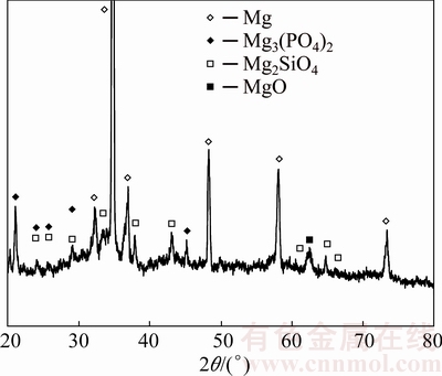
Fig. 6 XRD pattern of AZ91 alloy PEO-treated for 3 min with graphite nanoparticles
3.2 Corrosion resistance
The polarization curves for the samples of AZ91 and AZ80 are shown in Fig. 7 and the values of corrosion current densities and corrosion potentials, extrapolated from the curves in Fig. 7, are summarized in Table 2.
For AZ91, all the PEO-treated samples displayed an improved corrosion resistance compared with the untreated sample. In fact, all the PEO-treated samples were characterized by a corrosion current density, which is directly linked with the corrosion rate in the Faraday law, over one order of magnitude lower than that of the untreated sample. Moreover, also an increase in the corrosion potential was observed in the PEO-treated samples. The comparison among all the PEO-treated samples showed that the sample treated for 3 min with graphite nanoparticles in the electrolyte was characterized by a considerable improvement in the corrosion performance: this sample, in fact, showed an ennoblement in the corrosion potential of 0.5 V and a corrosion current density of two order of magnitude lower than that of the other PEO-treated samples (Fig. 7(b)). This behavior was related to the surface morphology, previously described. The coating in the samples treated for 3 min with graphite was thicker than all the other PEO coatings and the characteristic PEO pores present on the surface, were filled by the graphite. Moreover, the coating obtained with graphite nanoparticles was denser, thus improving the barrier effect of the oxide ceramic coating. These effects were less remarkable for the samples treated for 1 min with graphite (Fig. 7(a)), probably due to the thinner coatings. In fact, the sample treated for 1 min with graphite nanoparticles showed a corrosion resistance of only one order of magnitude lower than the one of the sample treated without graphite nanoparticles.

Fig. 7 Potentiodynamic polarization plots of AZ91 (a, b) and AZ80 (c, d) samples PEO-treated for 1 min (a, c) and 3 min (b, d)
Table 2 Corrosion potentials and corrosion current densities obtained for different PEO-treated samples from potentiodynamic polarization tests

For the AZ80 alloy, the anodic polarization plots are shown for the samples treated for 1 min in Fig. 7(c) and for the samples treated for 3 min in Fig. 7(d). Also for this alloy, all the PEO-treated samples exhibited an improved corrosion resistance compared with the untreated samples, with a decrease of more than one order of magnitude in the corrosion current density and an ennoblement in the corrosion potential. Also in this case, a remarkable improvement in the corrosion resistance was observed for the sample treated for 3 min with graphite nanoparticles, with a decrease of one order of magnitude in the corrosion current density and an increase of about 1.1 V in the corrosion potential, in comparison with other PEO-treated samples. The corrosion performance was correlated with the surface morphology, and in particular with the thicker, denser and ��graphite filled�� oxide ceramic coating of the sample obtained with the treatment of 3 min with graphite nanoparticles in the electrolyte.
EIS tests were performed to better understand the corrosion behavior of different samples. The equivalent circuits shown in Fig. 8 were used to fit the experimental data with the software Z-view. The Randles circuit (Fig. 8(a)) was employed for the untreated substrates, since only the natural oxide layer was present, whereas for the coated samples, the circuit shown in Fig. 8(b) was used. This circuit was ordinarily used to fit EIS data coming from PEO-coated samples [25,26], where R1 is the resistance of the solution; R2 is related to the polarization resistance of the external porous layer; R3 represents the polarization resistance of the internal barrier layer. In the circuit a constant phase element instead of a capacitance was used, since often the measured capacitance is not ideal. In this case, CPE1 is correlated with the porous layer, whereas CPE2 with the barrier layer.
The impedance representation of CPE is written as
Z(CPE)=1/[Q(j��)n] (1)
where �� is the angular frequency and Q is the constant phase element. The number n is an empirical exponent and can assume the value of 1 in the case of a perfect capacitor, and 0 in the case of a perfect resistor. If the value of n is less than 1, Q behaves as a capacitor. If the value of the exponent n is approximately 1, Q is similar to a pure capacitor and can be considered valid the well-known Eq. (2):
C=��0��A/dox (2)
where C is the capacitance; ��0 is the permittivisty of vacuum; �� is the dielectric constant; A is the effective area; dox is the thickness of the oxide layer.
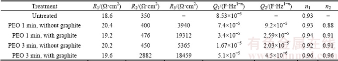
The results for the AZ91 magnesium alloy, reported in terms of Nyquist plots, and the results of the fitting of the experimental data (where a good fitting quality was obtained with a Chi square value that varied between 0.001 and 0.01) are shown in Figs. 9(a) and (b) and Table 3.
The reported EIS data confirmed the results coming from potentiodynamic polarization tests. The PEO- treated samples were characterized by higher corrosion performances if compared with the untreated ones. In fact, an increase of several orders of magnitude in the polarization resistance was recorded. The samples treated without graphite nanoparticles in the electrolyte showed a similar behavior to the sample treated for 3 min that was characterized by only slightly higher values of R2 and R3. However, the difference in the thickness of the coatings, which was found during SEM analysis, was confirmed by the fact that the value of Q2 in the sample treated for 1 min is one order of magnitude higher than that of the sample treated for 3 min. The difference in the values of Q1 is less important. Considering the samples treated with graphite nanoparticles, for both the treatments (1 and 3 min), a remarkable increase in the corrosion resistance was recorded if compared with the samples without graphite treatment. An increase both in the values of R2 and R3 can be noted, together with a decrease in the values of Q2. This fact can be linked with the presence of graphite that closed the pores on the surface of the sample and caused a variation in the discharge mechanism allowing to obtain thicker and denser protective coatings, if compared with the corresponding samples treated without graphite. The sample with the best corrosion performance resulted to be the one treated for 3 min with graphite nanoparticles: this sample was characterized by the highest values of R2 and R3. Moreover, the sample was also characterized by the lowest value of Q2 and, thus, it was characterized by the presence of the thickest protective layer, confirming the results previously reported in Section 3.1 (surface analysis). It should be noted that with EIS analysis it was possible to appreciate the improvement in the corrosion resistance of the sample treated for 1 min with graphite in comparison with the sample treated for the same time, but without graphite nanoparticles.
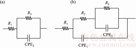
Fig. 8 Equivalent circuits employed for curve fitting of untreated sample (a) and of other treated samples (b)

Fig. 9 Nyquist plots of AZ91 (a, b) and AZ80 (c, d) samples PEO-treated for 1 min (a, c) and 3 min (b, d)
Table 3 Fitting results of experimental data for AZ91 magnesium alloy samples after EIS tests

EIS tests were also performed on the AZ80 magnesium alloy samples and the results, reported in terms of Nyquist plots, and the fitting of the experimental data (where a good fitting quality was obtained with a Chi square value that varied between 0.008 and 0.01) are reported in Figs. 9(c) and (d) and Table 4.
Also for AZ80 magnesium alloy EIS test was carried out to better evaluate the corrosion performance of different samples. The Nyquist plots showed that all the PEO-treated samples exhibited a remarkably higher corrosion performance than the untreated sample, with an increase of several orders of magnitude in the polarization resistance.
The samples treated for 1 and 3 min without graphite in the electrolyte had a similar corrosion behavior: only a slight increase in the value of R3 and a slight decrease in the value of Q2 were observed for the sample treated for 3 min, characterized by a thicker protective layer. The samples treated for 1 and 3 min with graphite showed a similar corrosion resistance and were characterized by a value of R3 almost one order of magnitude higher if compared with the samples treated without graphite. This fact can be explained with the presence of the graphite particles that filled the pores, increasing the barrier effect of the coating. Regarding the values of Q2, a comparison of the samples treated for the same time with and without graphite nanoparticles showed that the presence of graphite induced a decrease in the value of Q2 and so an increase in the thickness of the coating (in agreement with microstructural observations in Section 3.1). This fact was correlated with the modification in the discharge phenomena produced by the conductive graphite particles. Also for AZ80, EIS analysis allowed to better evaluate the corrosion resistance of different samples, due to its higher precision than anodic polarization tests: in particular, the behavior of the sample treated for 1 min with graphite particles was better explained.
Comparing the above two different magnesium alloys, the effect of the PEO treatment on the corrosion performances was more important for the AZ91 samples than for the AZ80 ones. This fact is in accordance with the literature, regarding the influence of alloy composition on the characteristics of PEO coatings on magnesium alloys [27,28], where the authors reported that increasing the aluminum content in the alloy produced an increase in the corrosion and mechanical properties of the PEO-coated samples.
3.3 Microhardness
In order to understand the influence of treatment time and graphite nanoparticles on the mechanical properties of the PEO layers, Vickers microhardness (HV0.1) tests were carried out in polished cross section. The results of micro-indentation tests on both PEO-treated alloys are shown in Table 1.
Table 4 Fitting results of experimental data for AZ80 magnesium alloy samples after EIS tests
For both the alloys, an increase in the treatment time produced an increase in the hardness of the coating, which is in agreement with literature data, indicating that an increase in the thickness of the coating produces an increase in the hardness [29]. Moreover, it was observed that the presence of graphite in the electrolyte produced an increase in the hardness in comparison with the samples obtained without graphite. This fact was related to microstructural changes in the coating: the presence of the graphite nanoparticles produced a densification of the coating and, usually, a denser coating is characterized by higher values of hardness. Similar behavior was found for graphite-containing PEO coating produced on aluminum alloys [19,30]. The increase in the hardness with the presence of the graphite nanoparticles was higher for AZ91 than that for AZ80 magnesium alloy.
3.4 Tribological behavior
Dry sliding tests were carried out on AZ91 and AZ80 samples according to different PEO process parameters (treatment time, presence or absence of graphite nanoparticles). Comparative tribological tests were also performed on the untreated alloys as reference.
As regarding friction, representative plots of the coefficient of friction (COF) recorded during the test as a function of sliding distance for different samples (untreated substrate and PEO-treated samples after 1 min with graphite nanoparticles) are compared in Fig. 10(a). The plots for PEO treatments carried out for 3 min on AZ80 with or without graphite nanoparticles are shown in Fig. 10(b). In all sliding tests, the untreated substrates gave highly comparable friction results (i.e., nearly completely overlapping COF vs sliding distance plots), therefore, only one of the untreated substrates (AZ80) was added in these comparisons, so as to make Figs. 10(a) and (b) more readable. A full presentation of average COF data can be found in Figs. 11(a) and (b).
The plots in Fig. 10(a) show that PEO-treatment increased the coefficient of friction of the alloys, due to the abrasive action of the rough and hard treated surface on the counterfacing steel. This COF enhancement on going from the untreated alloys (COF ~ 0.8 in dry sliding conditions [31] to the PEO-treated samples), was well documented in Refs. [32-34].

Fig. 10 Comparison of coefficient of friction as function of sliding distance for PEO-treated alloys (both after 1 min treatment, with graphite nanoparticles) and for untreated substrate (AZ80) (a) and coefficient of friction as function of sliding distance for PEO-treated AZ80 after 3 min treatment, with or without graphite nanoparticles, compared to untreated substrate (b)
Moreover, the plots in Fig. 10(a) show that both PEO-treated alloys (after 1 min of treatment, with graphite nanoparticles) underwent a transition from high to low friction values. In fact, at sliding distances of 150-200 and 250-300 m, a sharp decrease of COF was recorded for AZ91 and AZ80, respectively. Such a transition is due to onset of damage of the PEO layer (as demonstrated also by wear depth values and wear morphologies, discussed below) and subsequent involvement of the magnesium alloy substrate in the contact: after coating failure, the COF values for both PEO-treated alloys decreased down to values which are typical of the untreated magnesium alloy vs steel contact. The higher sliding distance to friction transition (i.e., the longer life) of the PEO-treated AZ80 alloy, can be explained considering the higher thickness of PEO coating: 50 and 30 ��m for AZ91, treated in the same conditions.
When increasing the treatment time from 1 to 3 min (Fig. 10(b)), a friction increase in comparison with the untreated substrate can be observed, as already discussed for samples treated for 1 min. However, the addition of graphite in the electrolyte slightly decreased the COF, more noticeably when a steady-state condition was achieved (after about 150 m). The plots in Fig. 10(b) also show that, after 3 min treatment, no friction transitions (related to wear-induced failure of the PEO layer) took place during sliding, indicating a beneficial influence of treatment time prolongation on wear resistance.
The average COF value as a function of treatment condition (treatment time and presence or absence of graphite) is shown in Figs. 11(a) and (b).
The average COF data in Figs. 11(a) and (b) demonstrated that the addition of graphite nanoparticles was more effective in reducing friction in the case of the AZ91 alloy (Fig. 11(a)), for which also more remarkable variations of thickness, hardness and corrosion resistance were observed than for AZ80 (Fig. 11(b)). In detail the presence of graphite permitted to obtain a denser coating and work as solid lubricant reducing the friction coefficient. The effect was more visible in the alloy with higher content of aluminum (AZ91) in accordance with the results regarding the corrosion resistance and the hardness [27].

Fig. 11 Average coefficient of friction as function of PEO treatment time, with or without graphite nanoparticles, for AZ91 (a) and AZ80 (b) and wear scar depth as function of PEO treatment time, with or without graphite nanoparticles, for AZ91 (c) and AZ80 (d)
The average wear depth data are summarized in Figs. 11(c) and (d). As already pointed out when discussing friction data, a beneficial influence on wear resistance of treatment time prolongation from 1 to 3 min was observed: after 3 min PEO treatment, the wear depth was not detectable for all the coatings. In fact, in these conditions, profilometric measurements on wear scars only highlighted the presence of shallow and non-uniform polishing marks, combined with a thin transfer layer of iron oxides, due to tribo-oxidation of the steel counterface (as shown also by 3D digital micrographs in Fig. 12, where the iron oxide transfer layers appear red-brown). The images of wear scars in Fig. 12 also show that iron oxide tended to be less adherent on the surface of samples treated with graphite (Figs. 12(b)-(d)) than on the surface of samples without graphite (Figs. 12(a)-(c)), probably due to the lubricity of graphite.
However, the increase of treatment time from 1 to 3 min led to an increase of wear resistance for all the alloys, both with and without graphite nanoparticles. In fact, increasing treatment time generally increased the thickness of PEO layers (Table 1), which, in turn, directly influenced the load bearing capacity of the treated surface and thus played a significant role in preventing the adhesive/abrasive wear of the magnesium alloy substrate, as observed also by BLAWERT et al [32].
Wear data in Fig. 11 also show that, when the PEO-layers obtained by 1 min treatment failed, the wear depth became higher than that of the untreated substrates, due to the more efficient abrasive action of hard fragments from the PEO layer. This was demonstrated by extensive ploughing marks on the substrate, emerging at the center of wear scars after coating failure, as shown by SEM images in Fig. 13 (Region 3). When the coatings did not fail for all the durations of the test (i.e., in the case of all the PEO layers obtained by 3 min treatment), the wear depth of the treated alloys was two orders of magnitude lower than that of the untreated ones.
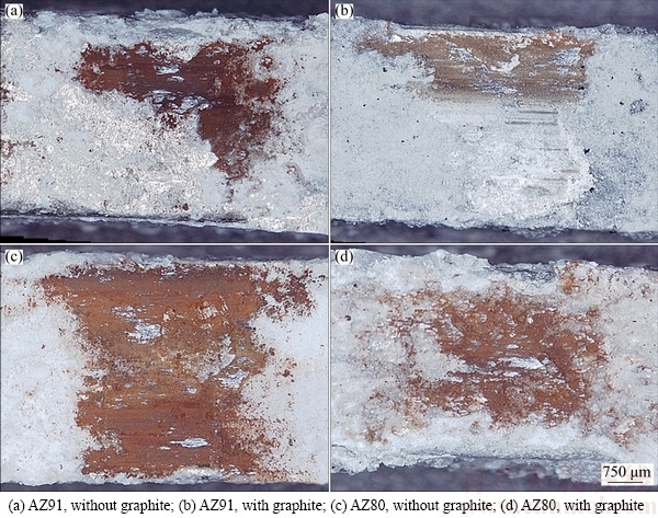
Fig. 12 Wear scar morphologies (3D-digital micrographs) of PEO-treated surfaces obtained by 3 min treatment after sliding against 100Cr6 steel

Fig. 13 Wear scar morphologies (SEM images) of PEO (1 min)-treated surfaces after sliding against 100Cr6 steel
In the case of AZ91 (Fig. 11(c)), the comparison of 1 min PEO treatment with or without graphite nanoparticles, showed that samples treated with graphite displayed a higher wear depth than those without graphite. This was probably due to their relatively high hardness, not combined, at the lowest treatment time, with a thickness increase as high as that obtained at 3 min. Therefore, in this case, the higher hardness of the PEO layer with graphite probably led to a more efficient micro-crack driven coating removal mechanism [35].
4 Conclusions
1) Samples of AZ91 and AZ80 magnesium alloys were PEO-treated using silicate- and phosphate-based alkaline solutions. The influence of graphite nanoparticles and treatment time on microstructure, corrosion, microhardness and tribological behavior was investigated.
2) The use of graphite nanoparticles produced PEO-layers with the pores almost totally filled up by graphite and the coatings were denser and harder than the ones obtained without graphite.
3) The coatings mainly consisted of magnesium and aluminum oxides, silicates and phosphates in accordance with the composition of the substrate and of the electrolyte.
4) Anodic polarization and EIS tests showed that graphite nanoparticles improved the corrosion performance of the coatings, in comparison with the coatings treated for the same time but without graphite. The graphite-containing coatings are characterized by higher hardness if compared with the ones without graphite.
5) Tribological tests showed that the prolongation of treatment time led to an increase of wear resistance. The addition of graphite nanoparticles to the electrolyte limited the formation of transfer layers on the worn surfaces and, mostly in the case of alloy AZ91, decreased the coefficient of friction by comparison with the PEO-treated surface without graphite.
6) Considering the two different magnesium alloys, the increase in the hardness and the corrosion resistance with the addition of graphite nanoparticles is more relevant for AZ91 alloy, where the aluminum content is higher. Also the improvement in the tribological performances is higher for AZ91 than for AZ80.
References
[1] LIANG J, BALA SRINIVASAN P, BLAWERT C,  M, DIETZEL W. Electrochemical corrosion behavior of plasma electrolytic oxidation coatings on AM50 magnesium alloy formed in silicate and phosphate based electrolytes [J]. Electrochimica Acta, 2009, 54: 3842-3850.
[2] MORDIKE B L, EBERT T. Magnesium properties-applications- potential [J]. Material Science Engineering A, 2001, 302: 37-45.
[3] WANG L, CHEN L, YAN Z C, WANG H L, PENG J Z. Growth and corrosion characteristics of plasma electrolytic oxidation ceramic films formed on AZ31 magnesium alloy [J]. The Chinese Journal of Process Engineering, 2009, 9: 592-597.
[4] SONG G, ATRENS A. Understanding magnesium corrosion��A framework for improved alloy performance [J]. Advanced Engineering Materials, 2003, 5: 837-858.
[5] SNIZHKO L O, YEROKHIN A L, PILKINGTON A, GUREVINA N L, MISNYANKIN D O, LEYLAND A, MATTHEWS A. Anodic processes in plasma electrolytic oxidation of aluminium in alkaline solutions [J]. Electrochimica Acta, 2004, 49: 2085-2095.
[6] CAO F H, LIN L Y, ZHANG Z, ZHANG J Q, CAO C N. Environmental friendly plasma electrolytic oxidation of AM60 magnesium alloy and its corrosion resistance [J]. Transactions of Nonferrous Metals Society of China, 2008, 18: 240-247.
[7] CUI X, YANG R, LIU C, YU Z, LIN X. Structure and corrosion resistance of modified micro-arc oxidation coating on AZ31B magnesium alloy [J]. Transactions of Nonferrous Metals Society of China, 2016, 26: 814-821.
[8] LIANG J, HU L, HAO J. Improvement of corrosion properties of micro arc oxidation coating on magnesium alloy by optimizing current density parameters [J]. Applied Surface Science, 2007, 253: 6639-6645.
[9] SRINIVASAN P B, BLAWERT C, DIETZEL W. Dry sliding wear behaviour of plasma electrolytic oxidation coated AZ91 cast magnesium alloy [J]. Wear, 2009, 266: 1241-1247.
[10] XIE H J, CHENG Y L, LI S X, CAO J H, CAO L. Wear and corrosion resistant coatings on surface of cast A356 aluminum alloy by plasma electrolytic oxidation in moderately concentrated aluminate electrolytes [J]. Transactions of Nonferrous Metals Society of China, 2017, 27: 336-351.
[11] MU W, HAN Y. Characterization and properties of the MgF2/ZrO2 composite coatings on magnesium prepared by micro-arc oxidation [J]. Surface and Coatings Technology, 2008, 202: 4278-4284.
[12] ARRABAL R, MATYKINA E, VIEJO F, SKELDON P, THOMPSON G E. Corrosion resistance of WE43 and AZ91D magnesium alloys with phosphate PEO coatings [J]. Corrosion Science, 2008, 50: 1744-1752.
[13] MATYKINA E, ARRABAL R, MONFORT F, SKELDON P, THOMPSON G E. Incorporation of zirconia into coatings formed by DC plasma electrolytic oxidation of aluminium in nanoparticle suspensions [J]. Applied Surface Science, 2008, 255: 2830-2839.
[14] WU X H, QIN W, GUO Y, XIE Z Y. Self-lubricative coating grown by micro-plasma oxidation on aluminum alloys in the solution of aluminate�Cgraphite [J]. Applied Surface Science, 2008, 254: 6395-6399.
[15] MU M, ZHOU X J, XIAO Q, LIANG J, HUO X D. Preparation and tribological properties of self-lubricating TiO2/graphite composite coating on Ti6Al4V alloy [J]. Applied Surface Science, 2012, 258: 8570-8576.
[16] MU M, LIANG J, ZHOU X J, XIAO Q. One-step preparation of TiO2/MoS2 composite coating on Ti6Al4V alloy by plasma electrolytic oxidation and its tribological properties [J]. Surface and Coatings Technology, 2013, 214: 124-130.
[17] ALIOFKHAZRAEI M, ROUHAGHDAM A S, SHAHRABI T. Abrasive wear behaviour of Si3N4/TiO2 nanocomposite coatings fabricated by plasma electrolytic oxidation [J]. Surface and Coatings Technology, 2010, 205: s41-s46.
[18] ALIOFKHAZRAEI M, ROUHAGHDAM A S. Fabrication of functionally gradient nanocomposite coatings by plasma electrolytic oxidation based on variable duty cycle [J]. Applied Surface Science, 2012, 258: 2093-2097.
[19] LV G H, CHEN H, GU W C, FENG W R, LI L, NIU E W, ZHANG X H, YANG S Z. Effects of graphite additives in the electrolytes on the microstructure and corrosion resistance of alumina PEO coatings [J]. Current Applied Physics, 2009, 9: 324-328.
[20] Standard test method for ranking resistance of materials to sliding wear using block on ring wear test. ASTM G77-05 [S]. 2005.
[21] CESCHINI L, DAEHN S, GARAGNANI L, MARTINI C. Friction and wear behavior of C4 Al203/AI composites under dry sliding conditions [J]. Wear, 1998, 38: 216-229.
[22] PEZZATO L, BRUNELLI K, GROSS S, MAGRINI M, M. Effect of process parameters of plasma electrolytic oxidation on microstructure and corrosion properties of magnesium alloys [J]. Journal of Applied Electrochemistry, 2014, 44: 867-879.
[23] AYDAY A, DURMAN M. Growth characteristics of plasma electrolytic oxidation coatings on aluminum alloys [J]. Acta Physica Polonica A, 2015, 127: 886-887.
[24] FORERO SOTOMONTE S, BLANCO PINZON C, GARCIA VERGARA S. Growth of PEO ceramic coatings on AA2024-T3 aluminium alloy [J]. Journal of Physics: Conference series, 2016, 687: 1-4.
[25] DEHNAVI V, SHOESMITH D W, LI LUAN B, YARI M, YANG LIU X, ROHANI S. Corrosion properties of plasma electrolytic oxidation coatings on aluminum alloys��The effect of the PEO process stage [J]. Material Chemistry Physics, 2015, 161: 49-58.
[26] SREEKANTH D, RAMESHBABU N, VENKATESWARLU K. Effect of various additives on morphology and corrosion behavior of ceramic coatings developed on AZ31 magnesium alloy by plasma electrolytic oxidation [J]. Ceramics International, 2012, 38: 4607-4615.
[27] ARRABAL R, MATYKINA E, HASHIMOTO T, SKELDON P, THOMPSON G E. Characterization of AC PEO coatings on magnesium alloys [J]. Surface and Coating Technology, 2009, 203: 2207-2220.
[28] CAKMAK E, TEKIN K C, MALAYOGLU U, SHRESTHA S. The effect of substrate composition on the electrochemical and mechanical properties of PEO coatings on Mg alloy [J]. Surface and Coating Technology, 2010, 204: 1305-1313.
[29] LI Q, LINAG J, WANG Q. Plasma electrolytic oxidation coatings on lightweight metals [C]//Modern Surface Engineering Treatments. Croatia: In Tech, 2013: 75-99.
[30] KIM Y, KIM D, PARK H, CHUNG U, CHUNG W. Effect of current step-down on the growth and hardness of PEO coatings on Al6061 alloy [J]. Procedia Engineering, 2011, 10: 2809-2814.
[31] BI G, LI Y, HUANG X, CHEN T, MA Y, HAO Y. Dry sliding wear behavior of an extruded Mg-Dy-Zn alloy with long period stacking ordered phase [J]. Journal of Magnesium Alloy, 2015, 3: 63-69.
[32] BLAWERT C, BALA SRINIVASAN P. Plasma electrolytic oxidation treatment of magnesium alloys [C]//Surface Engineering of Light Alloys: Aluminium, Magnesium and Titanium Alloys. Oxford: Woodhead Publishing, 2010: 155-183.
[33] RAPHEAL G, KUMAR S, BLAWERT C, DAHOTRE N B. Wear behavior of plasma electrolytic oxidation (PEO) and hybrid coatings of PEO and laser on MRI 230D magnesium alloy [J]. Wear, 2011, 9-10: 1987-1997.
[34] SRINIVASAN P B, LIANG J, BLAWERT C, DIETZEL W. Dry sliding wear behaviour of magnesium oxide and zirconium oxide plasma electrolytic oxidation coated magnesium alloy [J]. Applied Surface Science, 2010, 256: 3265-3273.
[35] JIANG B L, WANG Y M. Plasma electrolytic oxidation treatment of aluminium and titanium alloys [C]//Surface Engineering of Light Alloys: Aluminium, Magnesium and Titanium Alloys. Oxford: Woodhead Publishing, 2010: 110-154.
L. PEZZATO1, V. ANGELINI2, K. BRUNELLI1, C. MARTINI2, M. 1
1. Department of Industrial Engineering, University of Padua, Via Marzolo 9, 35131 Padova, Italy;
2. Department of Industrial Engineering, Alma Mater Studiorum, University of Bologna, V. le Risorgimento 4, 40136 Bologna, Italy
ժ Ҫ���õ����ӵ������(PEO)����AZ91 �� AZ80 þ�Ͻ�����Ʊ�Ϳ�㣬�о��ڵ��Һ������ʯī��������Ϳ�����ʴ�Ժ���ĥ���ܵ�Ӱ�졣���õ��ҺΪ���������κ����εļ�����Һ�����������ֲ�ͬ��PEO ����ʱ��(1 min��3 min)���ö���λ�������͵绯ѧ�迹��(EIS)����Ϳ�����ʴ�ԣ���ƽ��-��ʽ����Ħ��ʵ���������ĥ���ܡ���ɨ��羵��������(SEM-EDS)�۲�Ϳ�����֯��ò���۽ṹ��Ԫ����ɺ�Ϳ���ȡ����������ʯī������������Ϳ��ĺ�ȣ�����˱���Ŀ�϶��ʹͿ������ܣ�������������ʴ�Ժ���ĥ���ܡ�����AZ91���и��ߵ�������������ʴ���ܺ���ĥ���ܵ���߱�AZ80��������
�ؼ��ʣ������ӵ����������ĥ�ԣ���ʴ�ԣ�þ�Ͻ�ʯī������
(Edited by Wei-ping CHEN)
Corresponding author: L. PEZZATO; Tel: +39-0498275498; E-mail: luca.pezzato@unipd.it
DOI: 10.1016/S1003-6326(18)64659-X

