Trans. Nonferrous Met. Soc. China 22(2012) s717-s721
Polyaniline and multi-walled carbon nanotube composite electrode for rechargeable battery
Yu-Jeong LIM1, Min-Young PARK1, Sang-Keol LEE 2, Won-Ki LEE 3, Nam-Ju JO1
1. Department of Polymer Science & Engineering, Pusan National University, Busan 609-735, Korea;
2. Hankook Tire Co. Ltd., Daejeon 305-725, Korea;
3. Department of Polymer Engineering, Pukyong National University, Busan 608-739, Korea
Received 21 May 2012; accepted 6 October 2012
Abstract: The multi-walled carbon nanotube was introduced into the polymer matrix (PANI) to improve the electric conductivity as well as mechanical properties of the original polymer matrix. PANI/multi-walled carbon nanotube (MWCNT) composites were synthesized via ex-situ and in-situ polymerization to improve their electrical property. And the DC conductivities of PANI/MWCNT according to content and diameter of MWCNT were measured by four-point probe. The highest electric conductivity of PANI/MWCNT composite is 20 S/cm when 0.3% (mass fraction) MWCNTs with 10 nm in diameter and 15 μm in length are added in composite.
Key words: polymer electrode; electric conductivity; multi-walled carbon nanotube; conducting polymer
1 Introduction
Lithium secondary battery using polymer electrode have attracted considerable attention since the demonstration of the electrochemical doping and undoping of polyacetylene by MACDIARMID et al [1]. Various kinds of conducting polymers have been examined as electrode materials like poly (p-phenylene), polyaniline (PANI), polythiophene, and polypyrrole by many researchers [2-5], because they have some important characteristics such as long cyclic life, low self-discharge rate, endurance to overdischarge, low cost, flexible shape, and easy to make thin films [6]. Among them, PANI has been most extensively studied because it exhibits a good environmental stability and its electrical properties can be modified by the oxidation state and the degree of protonation [7]. However, the electrodes of conducting polymers have some necks related to conductivity and temperature dependence, affecting the performance of electrodes. They might limit their application in energy storage devices [8].
Carbon nanotubes (CNTs) have demonstrated a wealth of exceptional structure, a narrow distribution size, highly accessible surface area, low resistivity, good mechanical and electrical properties, and high stability that have made them show a lot of potential for a vast range of applications including quantum wire, tips for scanning probe microscopy [9]. Recently, it has been shown experimentally that the introduction of CNTs into polymer matrix improves the electric conductivity as well as the mechanical properties of the original polymer matrix [10-12]. In this work, PANI/multi-walled carbon nanotube (MWCNT) composites were synthesized via ex-situ and in-situ polymerization with different sizes and contents of MWCNT to be used as electrode materials for rechargeable batteries.
2 Experimental
2.1 Materials
Aniline (Junsei Chemical Co. Ltd., Japan), ammoniumpersulfate (APS; Junsei Chemical Co. Ltd., Japan), HCl (Junsei Chemical Co. Ltd., Japan) as the solvent and six kinds of MWCNTs (diameter of 10 nm, length of 1-2 μm; diameter of 20-40 nm, length of 1-2 μm; diameter of 60-100 nm, length of 1-2 μm; diameter of 20-40 nm, length of 5-15 μm; diameter of 60-100 nm, length of 5-15 μm; TCI Co., Japan) were used without further purification. Camphor sulfonic acid (CSA; Aldrich Co., USA) was used for secondary doping process. Cetyl trimethyl ammonium bromide (CTAB; Junsei Chemical Co. Ltd., Japan) and 1,3-dimethyl-3,4, 5,6-tetrahydro-2(1H)-pyrimidinone (DMPU; Aldrich Co., USA) were used as the surfactant and organic solvent to dissolve the materials, respectively.
2.2 Synthesis of pure polyaniline
Aniline monomer dissolved in 1 mol/L HCl and the APS dissolved in 1 mol/L HCl were cooled down at 0 °C. And then a solution containing the oxidant was slowly added into the aniline solution with a constant dropping speed at 5 mL/h. After a few minutes, the dark suspension became green, indicating the formation of PANI, being left overnight. PANI emeraldine salt was obtained by filtering and rinsing the precipitate. In order to make PANI emeraldine base (EB) state, NH4OH was added.
2.3 PANI/MWCNT composites synthesized via ex-situ and in-situ polymerization
In ex-situ polymerization, MWCNTs dissolved in DMPU were sonicated at room temperature to disperse the CNTs over 2 h. And then PANI EB powder and CSA were added for secondary doping process.
On the other hand, in the in-situ polymerization, CTAB and MWCNT were added into 1 mol/L HCl solution and sonicated over 2 h to obtain well dispersed suspensions. A pre-cooled solution of aniline monomer and 1 mol/L HCl solution containing oxidant were added sequentially to the above suspensions and then left overnight. After that, the resulting precipitate was filtered and rinsed with distilled water and ethanol several times. The remaining mixture was then dried under vacuum at room temperature and the secondary doping process was performed with CSA solution dissolved in DMPU over 18 h.
Pure PANI electrode and PANI/MWCNT composite electrode were fabricated by solution casting method on an Al foil and dried at 70 °C in a convection oven to prepare a free-standing film.
2.4 Characterizations
The results of polymerization were investigated by FTIR (Jasco 460 Plus) spectroscopy in the range of 500-4000 cm-1. Electric conductivities of pure PANI and PANI/MWCNT composite electrodes were measured by four-point probe (A.I.T CMT-SR1000N). And the morphology of specimen was confirmed by scanning electron microscope (SEM, JSM-6700F) and transmission electron microscope (TEM, ASAP 2010). Electrochemical properties were investigated by cyclic voltammetry(VSP) and discharge capacity on cycle.
3 Results and discussion
3.1 FT-IR measurement
Figure 1 shows the FTIR spectra of pure PANI and PANI/MWCNT composites. For all samples, FTIR spectra exhibit the clear presence of benzenoid and quinoid ring vibrations at 1500 cm-1 and 1600 cm-1, respectively [13-14].
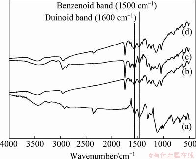
Fig. 1 FTIR spectra of pure PANI (a) and PANI/MWCNT composites with 0.1% (b), 0.2%-0.4% (c), and 0.5%-10% (d) of MWCNTs
The IR spectra of PANI/MWCNT composites illustrate several clear differences from the spectrum of the pure PANI. The PANI/MWCNT composite spectra exhibit an inverse intensity ratio of 1600 cm-1/1500 cm-1 compared with that of the pure PANI. This reveals that the quinoid unit in the PANI/MWCNT composite is richer than that in the pure PANI. This fact may suggest that interaction between PANI and MWCNT promotes or stabilizes the quinoid ring structure. In general, aromatic structures are known to interact strongly with the basal plane of graphitic surfaces via π-stacking [15]. As a result, the π-bonded surface of MWCNT might interact strongly with the conjugated structure of PANI, especially through the quinoid ring.
3.2 Electric conductivities according to size and content of MWCNTs
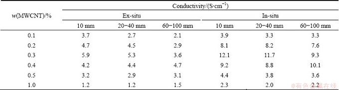
MWCNT exhibits different mechanical and electric properties according to its length and diameter. Table 1 and Table 2 show the electric conductivities of PANI/MWCNT composites with 1-2 μm in length and with 5-15 μm in length of MWCNT, respectively. From the result, PANI/MWCNT composite synthesized via in-situ polymerization shows higher conductivity than that via ex-situ polymerization. In cases of PANI/MWCNT composites with same length and diameter, the composite with 0.3% of MWCNT shows the highest electric conductivity. And as the length of MWCNT is long and the diameter of MWCNT is small, PANI/MWCNT composite exhibits high conductivity. This means MWCNT having high aspect (length/ diameter) ratio exhibits high electric conductivity. This may arise from that high aspect ratio materials are able to have the greater surface area and the more hopping site [16]. Finally, the highest electric conductivity of 20 S/cm was obtained in the case of PANI/MWCNT composite having 0.3% of MWCNTs with 10 nm in diameter and 5-15 μm in length.
Table 1 Conductivities of PANI/MWCNT composites with 1-2 μm in length of MWCNTs
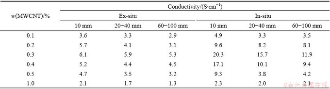
Table 2 Conductivities of PANI/MWCNT composites with 5-15 μm in length of MWCNTs
3.3 Morphology of PANI/MWCNT composites
Figure 2 shows the TEM images of PANI/ MWCNT composites with different diameters of MWCNT. PANI/MWCNT composite having smaller diameter shows the better structure which may give remarkable rise to conductive pathways and lead to high conductivity [17].
Figure 3 shows the SEM images of PANI/ MWCNT composite surfaces synthesized with different methods. In Fig. 3(a), there are some bundles of particle over 200 nm and empty spaces. On the other hand, Fig. 3(b) shows no empty space. That is, in-situ polymerization makes better conductive pathway which is able to allow electron to move, since the distance among hopping sites is closer and there is no vacancy.
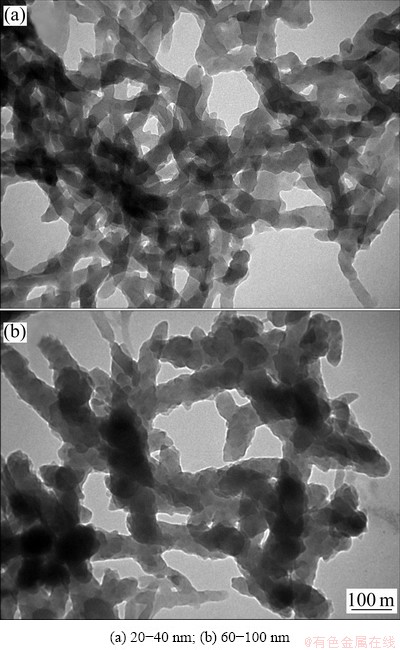
Fig. 2 TEM images of PANI/MWCNT composites with different diameters of MWCNT
3.4 Electrochemical measurements
Figure 4 shows cyclic voltammetries of pure PANI and PANI/MWCNT composite having 0.3% of MWCNTs with diameter of 10 nm and length of 5-15 μm. Pure PANI shows only one oxidation and reduction peak. However, in case of PANI/MWCNT composite peak shows upper two peaks corresponded to the oxidation and lower two peaks corresponded to reduction. It results from the correlation between the electrochemical reaction sites in the electrode [15]. In case of PANI/MWCNT composite electrode, the sp2 carbons in MWCNT compete with the CSA-ion used as a dopant, so this interaction between MWCNT and dopant has an effect on more active oxidation and reduction reaction in the electrode.
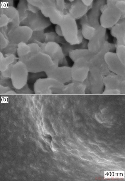
Fig.3 SEM images of PANI/MWCNT composites synthesized viaex-situ (a) and in-situ (b) polymerization
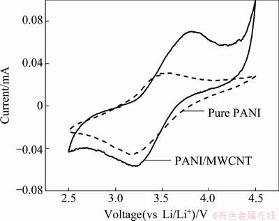
Fig. 4 Cyclic voltammetry of pure PANI and PANI/MWCNT composite having 0.3% of MWCNTs with diameter of 10 nm and length of 5-15 μm at a scan rate of 0.1 mV/s (voltage range: 2.5-4.5 V)
3.5 Capacity and cycle stability
The variation of the discharge capacity with the cycle number for pure PANI and PANI/MWCNT composites is shown in Fig. 5. The discharge capacities of three samples slowly decreased after about 5 cycles. This suggests that a slow activation process occurs during the charge-discharge process [18]. In contrast to the discharge capacity of pure PANI is only 42 A・h/kg, PANI/MWCNT composite electrode via ex-situ and in-situ polymerization are 51.5 and 54.5 A・h/kg, respectively. After 30 cycles, pure PANI electrode shows 88% of cycle stability, while both PANI/MWCNT composite electrodes show over 90% of cycle stability. Then it can be found that the reversible discharge capacity and cycle performance are improved by introducing MWCNT. The main reason may be that the addition of MWCNT to PANI matrix makes the composite with an interwoven fibrous structure, which improves the conductivity and facilities access of electrolyte [19].
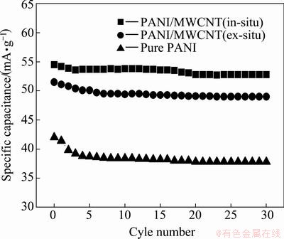
Fig. 5 Specific discharge capacities with cycle number for pure PANI and PANI/MWCNT composites
4 Conclusions
Polyaniline and multi-walled carbon nanotube (PANI/MWCNT) composites were prepared in order to improve the electrochemical performance of polymer electrode for rechargeable battery. MWCNTs having different sizes and contents were used and PANI/MWCNT composites were synthesized via ex-situ and in-situ polymerization. Electric conductivity is improved when the aspect ratio of MWCNT is high and in-situ polymerization is done. And PANI/MWCNT composite having MWCNT with high aspect ratio shows the appropriate morphology which gives remarkable rise to conductive pathways and leads to high conductivity. Also PANI/MWCNT composite electrode synthesized via in-situ polymerization shows the better structure to lead to high conductivity than that via ex-situ polymerization. The highest electric conductivity of 20 S/cm is achieved for the case of PANI/MWCNT having 0.3% of MWCNT with diameter of 10 nm and length of 5-15 μm. From the CV data, it is revealed that PANI/ MWCNT composite electrode shows excellent active oxidation and reduction reaction since MWCNT plays a role as a dopant like a CSA-ion. And PANI/MWCNT composite electrode has processed good discharge capacity and cycle stability.
References
[1] MACDIARMID A G, MU S L, SOMASIRI N L D, WU W, Polyaniline: A cathode-active material for rechargeable aqueous batteries [C]//Electrochem Soc Fall Meeting. New Orleans, 1984: 906-907.
[2] NULI Y, GUO Z, LIU H, YANG J. A new class of cathode materials for rechargeable magnesium batteries: Organosulfur compounds based on sulfur-sulfur bonds [J]. Electrochem Commun, 2007, 9(8): 1913-1917.
[3] REHAN H H. A new polymer/polymer rechargeable battery: Polyaniline/LiClO4(MeCN)/poly-1-naphthol [J]. J Power Sources, 2003, 113(1): 57-61.
[4] KARAMI H, MOUSAVI M, SHAMSIPUR M. A novel dry bipolar rechargeable battery based on polyaniline [J]. J Power Sources, 2003, 124(1): 303-308.
[5] LI J, ZHAN H, ZHOU L, DENG S, LI Z, ZHOU Y. Polyaniline-based polyorganodisulfide redox system of high energy for secondary lithium batteries [J]. Electrochem Communi, 2004, 6(6): 515-519.
[6] RYU K S, KIM K M, KANG S G, LEE G J, JOO J, CHANG S H. Electrochemical and physical characterization of lithium ionic salt doped polyaniline as a polymer electrode of lithium secondary battery [J]. Syn Met, 2000, 110(3): 213-217.
[7] KIM B J, OH S G, HAN M G, IM S S. Synthesis and characterization of polyanilines nanoparticles in SDS micellar solutions [J]. Syn Met, 2001, 122(2): 297-304.
[8] SANCHEZ DE PINTO M I, MISHIMA H T, LOA PEZ DE MISHIMA B A. Polymers and copolymers of pyrrole and thiophene as electrodes in lithium cells [J]. J Appl Electrochem, 1997, 27(7): 831-838.
[9] TANS S J, VERSCHUEREN A R M, DEKKER C. Room-temperature transistor based on a single carbon nanotube [J]. Nature, 1988, 393(6680): 49-52.
[10] SCHADLER L S, GIANNARIS S C, AJAYAN P M. Load transfer in carbon nanotube epoxy composites [J]. Appl Phys Lett, 1988, 73(26): 3842-3844.
[11] WAGNER H D, LOURIE O, FELDMAN Y, TENNE R. Stress-induced fragmentation of multiwall carbon nanotubes in a polymer matrix [J]. Appl Phys Lett, 1998, 72(2): 188-190 .
[12] QIAN D, DICKEY E C, ANDREWS R, RANTELL T. Load transfer and deformation mechanisms in carbon nanotube-polystyrene composites [J]. Appl Phys Lett, 2000, 76(20): 2868-2870.
[13] QUILLARD S, LOUARN G, LEFRANT S, MACDIARMID A G. Vibrational analysis of polyaniline: A comparative study of leucoemeraldine, emeraldine, and pernigraniline bases [J]. Phys Rev B, 1994, 50(17): 12469-12508.
[14] FURUKAWA Y, UEDA F, HYODO Y, HARADA I, NAKAJIMA T, KAWAGOE T. Vibrational spectra and structure of polyaniline [J]. Macromolecules, 1998, 21(5): 1297-1305.
[15] CHEN R J, ZHANG Y, WANG D, DAI H. Noncovalent sidewall functionalization of single-walled carbon nanotubes for protein Imobilization [J]. J Am Chem Soc, 2001, 123(4): 3838-3839.
[16] SEUNG Y T, Y KIM N. Properties of polymer/carbon nanotube composites [J]. Prospectives of Industrial Chemistry, 2006, 9(6): 37-43.
[17] WU T M, LIN Y W, LIAO C S. Preparation and characterization of Polyaniline/multi-walled carbon nanotube composite [J]. Carbon, 2005, 43(4): 734-740.
[18] WANG C Y, MOTTAGHITALAB V, TOO C O, SPINKS G M, WALLACE G G. Polyanilines and polyaniline-carbon nanotube composite fibers as battery materials in ionic liquid electrolyte [J]. J Power Sources, 2007, 163(2): 1105-1109.
[19] CHENG F, TANG W, LI C, CHEN J, LIU H, SHEN P, DOU S. Conducting poly(aniline) nanotubes and nanofibers: Controlled synthesis and application in lithium/poly (aniline) rechargeable batteries [J]. Chem Eur J, 2006, 12(11): 3082-3088.
(Edited by ZHAO Jun)
Foundation item: project (2012-0007594) supported by Basic Science Research Program through the National Research Foundation of Korea (NRF) funded by the Ministry of Education, Science and Technology
Corresponding author: Nam-Ju JO; Tel: +82-51-510-2462; E-mail: namjujo@pusan.ac.kr
DOI: 10.1016/S1003-6326(12)61793-2

