
Experimental investigation of friction coefficient in tube hydroforming
Hyae Kyung YI 1, Hong Sup YIM 1, Gun Yeop LEE 1, Sung Mun LEE 1, Gi Suk CHUNG 2, Young-Hoon MOON 1
1. Engineering Research Center for Net Shape and Die Manufacturing, School of Mechanical Engineering,
Pusan National University, Busan 609-735, Korea;
2. Technical Research laboratories, POSCO, Jeonnam 545-090, Korea
Received 21 April 2010; accepted 10 September 2010
Abstract: The friction coefficient between tube and die in guide zone of tube hydroforming was obtained. In hydroforming, the tube is expanded by an internal pressure against the tool wall. By pushing the tube through tool, a friction force at the contact surface between the tube and the tool occurs. In guiding zone, the friction coefficients between tube and die can be estimated from the measured axial feeding forces. In expansion zone, the friction coefficients between tube and die can be evaluated from the measured geometries of expanded tubes and FE analysis.
Key words: tube hydroforming; friction coefficient; lubricant; axial force; internal pressure
1 Introduction
The hydroforming is a process to expand metal tubes through high fluid pressure from inside in a closed forming die[1-3]. The hydroforming process is widely applied to the automotive industry, such as body, chassis and frame, and rapidly spread to other industrial fields [4-7]. In hydroforming process, the tube is expanded by an internal pressure against the tool wall. By pushing the tube through the tool, a friction force at the contact surface between the tube and the tool occurs.
In a typical tube hydroforming process, there are two different zones shown in Fig.1, which are the so-called guiding zone and the expansion zone[8-9]. In the guiding zone, the tube and the die are in full contact during the process and the material is pushed into the deformation zone by axial feeding cylinders. In expansion zone, the deforming material at the die-material interface can undergo surface expansion. The tube is expanded by an internal pressure against the tool wall. By pushing the tube through the tool, a friction force at the contact surface between the tube and the tool occurs. Therefore, the friction at the die-tube interface is affected by the formability in tube hydroforming. With low friction, more homogeneous deformation can be achieved[10-11].
In this study, the friction test method is proposed to obtain the friction coefficient between tube and die in

Fig.1 Friction zones in tube hydroforming process
tube hydroforming. And the friction coefficients are evaluated for different materials, die surface coating, viscosity of lubricants and internal pressures. The friction coefficients between tube and die can be estimated from the measured axial feeding forces in guiding zone and from the measured geometries of expanded tubes and FE analysis in expansion zone. The effects of the various internal pressures, viscosity of lubricants, tube materials, tube size and die surface coating on the friction forces and friction coefficients were discussed.
2 Experimental
2.1 Process variable
For this study, STKM11A and SS321, 304, 409 tubes were prepared in order to evaluate the effect of tube material and size. The tubes with outer diameters of 50.8 mm and 76.2 mm and thickness of 2.0 mm are used. The lubricants used in the friction tests can be divided into two groups: liquid-state and solid-state lubricants. The liquid lubricants with different viscosity and Teflon film were used, as well as no lubricant for comparison purposes. Each tube was tested at different internal pressures in the range of 10-50 MPa. The test was repeated using combination of tube, lubricant, internal pressure and die surface coating, respectively.
2.2 Friction test in guiding zone
There are two friction laws that are commonly used in metal forming: Coulomb’s friction law and shear friction law. While Coulomb’s law is more suitable for sliding contact with little deformation, the shear friction law is suitable for sliding objects subjected to bulk plastic deformation. The deformation modes in guiding zone of tube hydroforming are dominated by sliding, hence, Coulomb’s law may be applicable. Assuming Coulomb’s law, the interface friction coefficient can be determined by Eq.(1). The friction force Ff and normal load Fn are both measured by hydroforming system.
μ=Ff/Fn (1)
It assumed that the coefficient of friction is uniform at the interface throughout the whole tube length and the normal stress is equal to the internal pressure.
Fn=πpiDoL (2)
where pi is the internal pressure; Do is the out-diameter of tube; and L is length of tube. From Eq.(2), the friction coefficient can be expressed as
μ=Ff/(πpiDoL) (3)
In friction test of guiding zone, a lubricated tube is placed in a die with the same size as the out-diameter of the tube, as shown in Fig.2. The die is closed by the ram movement of a press. At the same time, the tube ends are loaded and sealed by two punches, and the tube is filled with fluid. And tube is pushed through a die by axial punch. Finally, the internal pressure, axial force and axial displacement are measured continuously throughout the test. The test tubes and die are cleaned with acetone before the friction test, then the surface of tube is smeared uniformly with various lubricants. And the total sliding distance is 30 mm.
2.3 Friction test in expansion zone
Three corner-fill tests were carried out to evaluate the friction coefficient for the expansion zone. Fig.3 shows the cross-section geometries of corner-fill test model. The tube is constrained by the die and can expand into the corners of the die with various lubricants. The corner-fill distance and thickness of expanded tube were measured.

Fig.2 Friction test in guiding zone: (a) Schematic drawing; (b) Appearance of testing apparatus

Fig.3 Cross-section geometries of corner-fill test model
FE simulations, using the commercial code LS-DYNA, were conducted for three models under various frictional conditions. And the FE analysis results were compared with the measured geometries of hydroformed tube. And the friction coefficients at various lubricants were obtained at similar geometries by comparing the experimental and FE analysis results.
3 Results and discussion
3.1 Friction coefficient in guiding zone
The relationships between the friction coefficients and the internal pressure at various lubrications are shown in Fig.4. The results from the friction test of guiding zone show that the viscosity of lubricant and internal pressure increases with decreasing the friction of coefficient of STKM11A tube. The friction coefficient without lubricant is higher than that with liquid lubricant. And the friction coefficient with liquid lubricant is higher than that of Teflon film. The friction coefficient decreases with increasing the internal pressure. The friction coefficients without lubricant are about 0.084 at 10 MPa, 0.034 at 30 MPa, 0.020 at 50 MPa. The friction coefficient decreases with increasing viscosity of lubricant at same internal pressure. The friction coefficient is 0.052 without lubricant, whereas those using viscosity 180, 320, 400 of liquid lubricant and Teflon are 0.031, 0.020, 0.018 and 0.002 at 20 MPa. And the friction coefficient is more sensitive to internal pressure with decreasing the viscosity of lubricant. The friction coefficient with Teflon film is about 0.002 at every condition and shows the lowest friction coefficient.
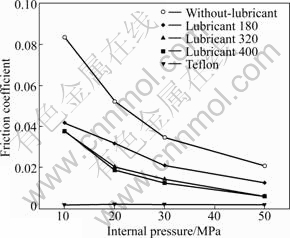
Fig.4 Friction coefficient distribution with different lubricants at internal pressures (STKM11A)
Fig.5 shows the effect of tube diameter on the friction coefficient. The friction coefficients of 180 lubricant are 0.031 for d 50.8, 0.027 for d 76.2 at 20 MPa, and 0.021 for d 50.8, 0.020 for d 76.2 at 30 MPa. The friction coefficient decreases with decreasing the diameter at same internal pressure and lubricant conditions. The normal force Fn increases with increasing the contact area, which is more effective than the increase of the friction force with friction coefficient increasing.
The relationships between the friction coefficient and the strength of material at various internal pressures and lubrications are shown in Fig.6(a). The effects of internal pressure and lubricant viscosity are like the preceding. The friction coefficients of 180 lubricant are 0.031 for STKM11A, 0.012 for SS321 at 20 MPa, and 0.020 for STKM11A, 0.008 for SS321 at 30 MPa.
Fig.6(b) shows the effect of the material, therefore, the friction coefficient decreases with increasing the strength of material under condition of same lubricant internal pressure.
Fig.7 shows the effect of die condition at various internal pressure conditions. The friction coefficients are 0.037 for coated die, 0.052 for uncoated die at 20 MPa. However, the friction coefficient has similar value as 0.031 at 20 MPa, irrespective of the die coating. Therefore, in lubrication condition, the die coating is independent on friction force.

Fig.5 Friction coefficient distribution with different lubricants, diameters and internal pressures
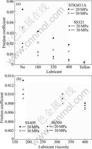
Fig.6 Friction coefficient distribution with different lubricants, materials and internal pressures: (a) STKM11A and SS321; (b) SS304 and SS409
3.2 Friction coefficient in expansion zone
FE simulation results and measured geometry of expanded tube are given in Tables 1, 2 and Fig.8. The friction coefficients were deducted by comparing FE analysis and measured geometries of expanded tubes. In the case of STKM11A, the friction coefficients are obtained from 0.168 to 0.130 for lubricants 180-400. SS304 has lower friction coefficient than STKM11A, from 0.095 to 0.089 for lubricants 180-400. The friction coefficient decreases with increasing the strength of material. The maximum thinning of thickness represented at contact area of die and tube. The contact length is longer in the order of hexagonal, square, triangular shape. The triangular shaped die has the longest corner fill length. The friction coefficient with Teflon film is obtained a similar value, about 0.001.
Table 1 Measured geometry of expansion tubes with friction coefficient

Table 2 Measured geometry of expansion tubes with lubricants


Fig.7 Effect of die coating and lubricant on COF

Fig.8 Measured geometries of expansion friction test model: ① Thickness at contact region; ② Thickness at expansion region; ③ Maximum expansion length; ④ Contact length; ⑤ Half of contact length
4 Conclusions
The friction coefficient decreases with increasing the strength and diameter of materials, lubricants viscosity and internal pressures. Also the friction coefficient without lubricant decreases with decreasing die coating; however, the friction forces with lubricant are not influenced by die coating. The friction coefficient in guiding zone is lower than that in expansion zone. The friction coefficient at expansion zone decreases with increasing the lubricants viscosity and is not sensitive of the internal pressure. The friction coefficients are similar for different geometries.
Acknowledgement
This work was partially supported by grants-in-aid for the National Core Research Center Program from MEST/KOSEF
References
[1] SOKOLOWSKI T, GEKE K, AHMETOGLU M, ALTAN T. Evaluation of tube formability and material characteristics: Hydraulic bulge testing of tubes [J]. Journal of Materials Processing Technology, 2000, 98: 34-40.
[2] HWANG Y M, ALTAN T. Process fusion: Tube hydroforming and crushing in a square die [J]. Journal of Engineering Manufacture, 2004, 218B: 169-174.
[3] VOLLERTSEN F, PLANCAK. On possibilities for the determination of the coefficient of friction in hydroforming of tubes [J]. Journal of Materials Processing Technology, 2002, 125: 412-420.
[4] Lang L H, Wang Z R, Kang D C, Yuan S J, Zhang S H, Danckert J, Nielsen K B. Hydroforming highlights: Sheet hydroforming and tube hydroforming [J]. Journal of Materials Processing Technology, 2004, 151: 165-177.
[5] Ahmetoglu M, Sutter K, LI X J, ALTAN T. Tube hydroforming: Current research, applications and need for training [J]. Journal of Materials Processing Technology, 2000, 98: 224-231.
[6] KWAN C T, LIN F C. Investigation of T-shape tube hydroforming with finite element method [J]. The International Journal of Advanced Manufacturing Technology, 2003, 21: 420-425.
[7] ZHANG S H. Developments in hydroforming [J]. Journal of Materials Processing Technology, 1999, 91: 236-245.
[8] hwang yrong maw, huang li shan, altan taylan. Friction tests in tube hydroforming [J]. Proceedings of the Institution of Mechanical Engineers, Part B: Journal of Engineering Manufacture, 2005, 219: 587-594.
[9] NGAILE G, JAEGER S, TAYLAN A. Lubrication in tube hydroforming (THF) Part 1. Lubrication mechanisms and development of model tests to evaluate lubricants and die coatings in the transition and expansion zones [J]. Journal of Materials Processing Technology, 2004, 146: 108-115.
[10] MUAMMER KOC, ALTAN TAYLAN. Prediction of forming limits and parameters in the tube hydroforming process [J]. Int J Machine Tools & Manufacture, 2002, 42: 123-138.
[11] lei l p, kang b s, KANG S J. Prediction of the forming limit in hydroforming process using the finite element method and a ductile fracture criterion [J]. Journal of Materials Processing Technology, 2001, 113: 673-679.
(Edited by LI Yan-hong)
Corresponding author: Young-Hoon MOON; Tel: +82-51-5102472; E-mail: yhmoon@pusan.ac.kr

