Trans. Nonferrous Met. Soc. China 22(2012) s287-s293
Springback mechanism and compensation of cryogenic Ti alloy tube after numerically controlled bending
ZHAN Mei, ZHAI Hua-dong, YANG He
State Key Laboratory of Solidification Processing, School of Materials Science and Engineering, Northwestern Polytechnical University, Xi’an 710072, China
Received 28 August 2012; accepted 25 October 2012
Abstract: The springback mechanism for a large-diameter thin-walled CT20 titanium alloy tube with an outside diameter of 85 mm and a wall thickness of 2.5 mm (denoted as D85 mm×t2.5 mm) was investigated using numerical simulation. The results show that the areas among the crest lines and the neutral layer unload significantly, whereas the areas adjacent to the neutral layer unload indistinctively. These differences lead to a reverse loading in certain areas of bent tube and an obvious tensile-compressive stress concentration in the area adjacent to the neutral layer after springback. The variation rules of springback angle and springback radius with bending radius and bending angle were studied. These data were used to propose a springback compensation method, which was verified to be effective in an example study.
Key words: CT20 titanium alloy; large-diameter thin-walled tube; numerically controlled (NC) bending; springback; springback compensation
1 Introduction
With the development of aerospace, aviation, automotive and other high-technology industries, bending components and technology are increasingly important [1-3]. Among the developed tube bending and forming the methods, numerically controlled (NC) tube bending (Fig. 1), a complex non-linear physical process under multi-die constraints and multi-factor coupling effects, is frequently employed due to its many advantages, such as economy, high efficiency and the large-quantity batch production with high precision and stable quality [4]. CT20 is a medium-strength cryogenic titanium alloy near α phase that was developed by Northwest Institute for Nonferrous Metal Research of China [5,6]. It has good cryogenic deforming capability and retains excellent plasticity and ductility at low temperature. Thus, a large-diameter thin-walled CT20 titanium alloy tube is used widely in the liquid-hydrogen pipeline systems of spacecraft engines. Because of the alloy’s high specific strength and low elastic modulus, significant springback occurs after NC bending for CT20 tubes, which will greatly affect the formation precision of the bent tubes. Therefore, it is necessary to study the deformation mechanism and rules during NC bending and springback processes for large-diameter thin-walled CT20 titanium alloy tubes.
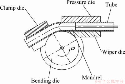
Fig. 1 Schematic diagram of NC tube bending
Significant effort was applied to studying the mechanism and rules of tube bending and springback using analytical, experimental and numerical approaches [7-9]. However, many of these studies focused on the bending and springback mechanism, rules and control of aluminium alloy tubes, stainless steel tubes and small-diameter thick-walled titanium alloy tubes [10-13]; the results regarding the mechanism and rules for large-diameter thin-walled cryogenic titanium alloy tube were rarely reported. Thus, in this work, the finite element method (FEM) was employed to investigate the bending and springback mechanisms for large-diameter thin-walled CT20 titanium alloy tubes, and a method was proposed to predict and control the springback.
2 Research methods
The NC bending of a CT20 tube was simulated on an ABAQUS/Explicit platform, and the springback was simulated on an ABAQUS/Standard platform. The employed FE model was established by WANG et al [14], and the forming parameters for CT20 tube NC bending are the same as that used in Ref. [14].
3 Results and discussion
3.1 Bending and springback mechanism
Figures 2 and 3 show the hoop stress and axial stress distribution of CT20 titanium alloy tubes during bending and springback processes, respectively. As illustrated in the figures, the axial stress is almost always larger than the hoop stress.
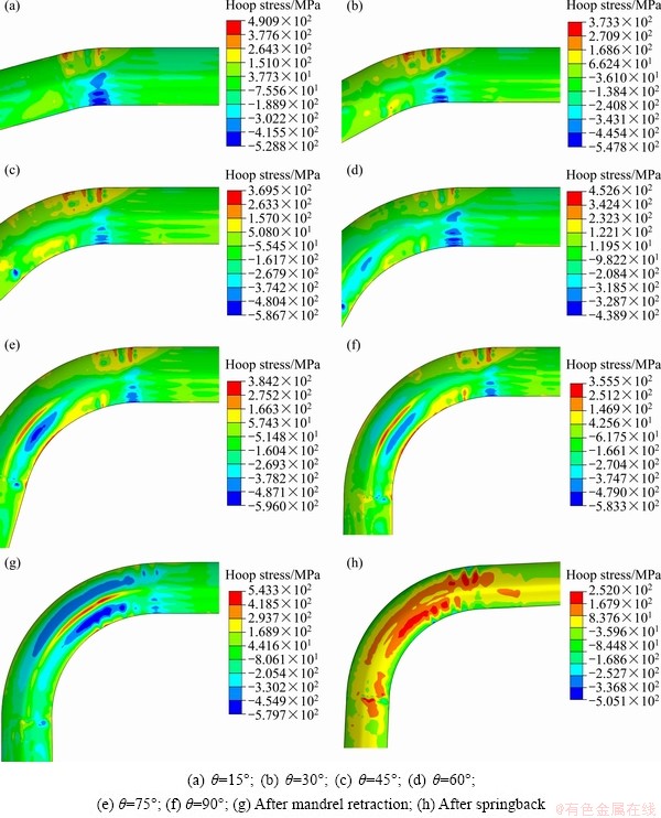
Fig. 2 Hoop stress distribution during bending and springback (θ is bending angle)
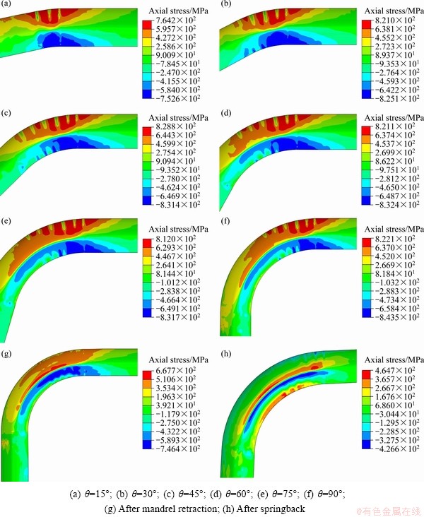
Fig. 3 Axial stress distribution during bending and springback
As observed from Fig. 2, the hoop tensile stress along the outer side of the bent tube is smaller than the hoop compressive stress along the inner side throughout the bending process.
As observed from Fig. 3, the axial stress along the inner and outer sides of the bent tube increases rapidly at the beginning of the bending process. When the bending angle exceeds 30° the axial stress remains almost constant, which indicates a transition into the stable deformation stage. In the stable deformation stage, the axial compressive stress along the inner side of the bent tube is larger than the axial tensile stress along the outer side. Once the mandrel is retracted, the axial stress unloads to a certain degree as a result of the lack of constraint of the mandrel. Moreover, the axial tensile stress unloads to a greater degree than the axial compressive stress.
Comparing the axial stress before and after springback, the axial stress unloads greatly during springback and the compressive stress unloads to a greater degree than the tensile stress. After springback, tensile-compressive stress concentration areas exist in the region near the neutral layer where the strain is zero during the bending and a reverse loading phenomenon in the axial stress occurs on the inner and outer sides of the bent tube. These results are different from the variation of axial stress for aluminum alloy tubes before and after springback [15,16]. To explain this difference, measuring planes are defined through bending center O, as shown in Fig. 4, where α is the angle between the measuring plane and the initial bending plane, and β is the angle on the measuring plane. Next, the variation of axial stress on the intersection curve of each measuring plane with the bent tube before and after springback is obtained, as shown in Fig. 5.
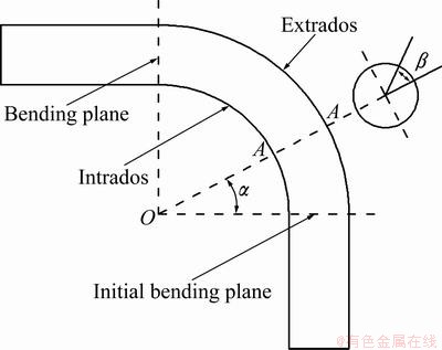
Fig. 4 Sketch of crest lines and measuring planes
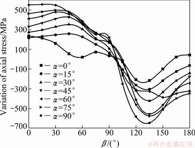
Fig. 5 Variation of axial stress on measuring plane before and after springback
Figure 5 shows that, with increasing α, the axial tensile stress along the outer side of the bent tube unloads more completely and the unloading of the axial compressive stress along the inner side first increases and then decreases. Moreover, the unloading of the axial stress of the bending portion is large when β is in the range of 15°-45° or 120°-150° and small when β is in the range of 75°-105°. Thus, the areas with the most significant unloading are among the crest lines and the neutral layer, and those with the least unloading are adjacent to the neutral layer. Thus, the tensile- compressive stress concentration areas occur near the neutral layer and the reverse loading areas occur along the inner and outer sides of the bent tube.
3.2 Effect of bending radius and angle on springback
Figure 6 shows the springback angle Δθ and springback radius ΔR as functions of the bending radius R and bending angle θ.
As observed from Fig. 6(a), the springback angle Δθ increases with the increase of bending angle θ and the difference in Δθ is not obvious for θ below 30°. Δθ first decreases and then increases as the bending radius R increases, and the critical bending angle between them is 30°. This behavior may result from the unstable and complicated contact conditions among the tube, bending die, pressure die, wiper die, mandrel, and balls under the small bending angle.
The increase in Δθ with θ is uneven with R, which means the interaction θ×R might have an effect on Δθ.
As shown in Fig. 6(b), the springback radius ΔR first decreases and then increases with increasing R and the critical bending angle between them is 45°. The explanation is similar to that for Δθ. However, the critical angle differs from that for Δθ, most likely because the constraints among the tube and dies have a slight effect on ΔR.
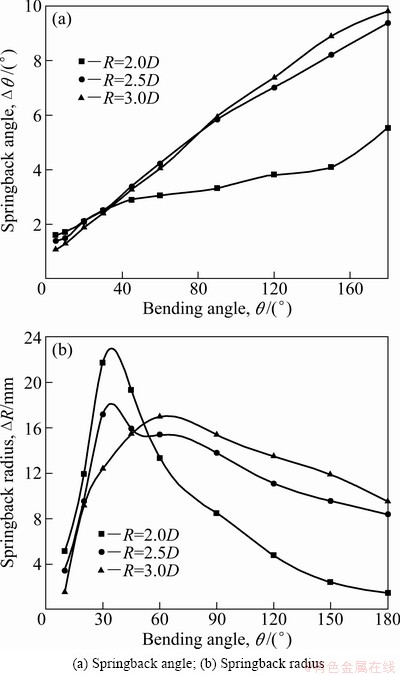
Fig. 6 Springback angle and springback radius for different R and θ
As observed in Fig. 6, with increasing θ, ΔR first increases and then decreases. This behavior is caused by several factors, including the increase in the total elastic strain of the bending portion with increasing θ, which increases ΔR. However, ΔR is also affected by the axial tensile force Fa: the larger the Fa is, the smaller the ΔR is. Due to the increase of the deforming force of the bent tube (Fig. 7), Fa increases with increasing θ [10]. All of these result in the fact that ΔR first increases and then decreases.
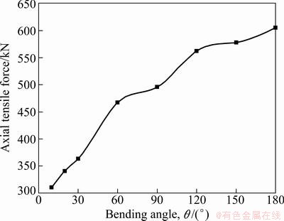
Fig. 7 Effect of bending angle on axial tensile force
Figure 6 also shows that Δθ and ΔR for R=3.0D are slightly larger than that for R=2.5D. This difference is due to the ratio of the plastic strain to the total strain εp/εt along the intrados of the bent portion for R=3.0D being slightly smaller than that for R=2.5D, as shown in Fig. 8. Thus, the total elastic strain components of the bending portion are slightly larger than that for R=2.5D.
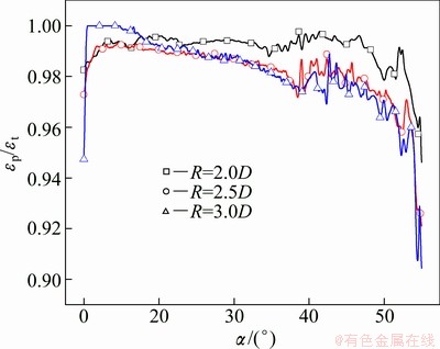
Fig. 8 εp/εt for intrados of bending portion at θ=90°
3.3 Springback compensation
The springback after the NC bending of the tubes will decrease the bending angle and increase the bending radius, which will greatly affect the formation precision of the bent tubes. Thus, considering the springback angle and radius, a method of springback compensation for thin-walled tube NC bending was presented as follows.
1) Establish the regression equations of springback angle Δθ and springback radius ΔR with bending angle θ and bending radius R, respectively (if the interaction θ×R affects Δθ and ΔR, it should be taken into account).
2) Determine initial bending angle and initial bending radius according to the regression equation established above.
3) Simulate the bending process at the initial bending angle and the initial bending radius and then calculate the errors Eθ and ER of the bending angle and bending radius, respectively. If the errors satisfy the accuracy requirement, the bending parameters can be applied to manufacturing. Otherwise, continue to the next step.
4) Compensate the bending angle and the bending radius with the errors, obtain a new bending angle and bending radius.
5) Repeat steps 3) and 4) until the errors meet the accuracy requirement.
In the following, an example of springback compensation for the bending of a D85×t2.5 mm CT20 titanium alloy tube was given to demonstrate the feasibility and reliability of the method. In this example, the expected bending angle is 100°, the bending radius is 200 mm, and |Eθ|≤0.1° and |ER|≤0.5 mm are required. The specific steps of the springback compensation are as follows.
1) Based on the variation of the springback angle Δθ with R and θ (greater than 30°) shown in Fig. 6(a), regression equation (1) is established. Regression equation (2) of the springback radius ΔR is established using Fig. 6(b). These two equations are verified to be significant:
Δθ=2.32077-0.2638(R/D)-0.03654θ+0.02919θ(R/D) (1)
ΔR=12.27033+2.806(R/D)-0.16912θ+0.03803θ(R/D) (2)
2) Determine the initial bending angle θ0 and the initial bending radius R0:
Δθ=θ0-100=2.32077-0.2638(R0/D)-0.03654θ0+0.02919θ0(R0/D),
ΔR=200-R0=12.27033+2.806(R0/D)-0.16912θ0+0.03803θ0(R0/D),
θ0=104.75°, R0=190.25 mm.
3) Set θ0 and R0 as the initial bending parameters and simulate the tube bending process. A practical bending angle of θp=99.75° and a practical bending radius of Rp=202.4 mm are achieved. The errors are as follows:
Eθ=100°-θp=0.27°, ER=200-Rp=-2.4 mm.
The errors fail the requirement, so the compensation is continued.
4) Determine the bending angle θ1 and bending radius R1 with the errors:
θ1=θ0+Eθ+0.2638(ER/D)+0.03654Eθ-0.02919θ0(ER/D)=104.951°,
R1=R0+ER-2.806(ER/D)+0.16912Eθ-0.03803θ0(ER/D)=187.82 mm.
5) Set θ1 and R1 as the bending parameters and simulate the tube bending process again. A practical bending angle of θp=100.079° and a practical bending radius of Rp=199.62 mm are achieved. The errors are as follows:
Eθ=100°-θp=0.079°, ER=200-Rp=0.38 mm.
The errors meet the requirement, which means that θ1 and R1 can be used as the bending parameters in the tube bending process.
Using the traditional method for compensating the bending angle only, the bending angle and bending radius are 100.051° and 202.18 mm respectively after two compensation iterations. Thus, only the error in the bending angle can meet the requirement.
Using the traditional method for compensating the bending radius only, the bending angle and bending radius are 99.834° and 200.33 mm respectively after three compensation iterations. Thus, only the error in the bending radius can meet the requirement.
These results show that the proposed method for the springback compensation for both the bending angle and bending radius for the bending of a Ti alloy tube is feasible and efficient.
4 Conclusions
1) The areas among the crest lines and the neutral layer unload significantly, whereas those adjacent to the neutral layer unload only slightly. These differences lead to the reversed loading in certain areas of the bent tube and the obvious tensile-compressive stress concentration in the areas adjacent to the neutral layer after the springback.
2) The springback angle and springback radius both first decrease and then increase with the increase of bending radius, with critical bending angles of 30° and 45°, respectively.
3) A springback compensation method for bending angle and bending radius simultaneously is proposed and proven to be effective by an example.
References
[1] HASHMI M S J. Aspects of tube and pipe manufacturing processes: Meter to nanometer diameter [J]. Journal of Materials Processing Technology, 2006, 179(1-3): 5-10.
[2] GUAN Y, POURBOGHRAT F, BARLAT F. Finite element modeling of tube hydroforming of polycrystalline aluminum alloy extrusions [J]. International Journal of Plasticity, 2006, 22: 2366-2393.
[3] AHMETOGLU M, ALTAN T. Tube hydroforming: State-of-the-art and future trends [J]. Journal of Materials Processing Technology, 2000, 98: 25-33.
[4] YANG He, SUN Zhi-chao, LIN Yan, LI Ming-qi. Advanced plastic processing technology and research progress on tube forming [J]. Journal of Plasticity Engineers, 2001, 8(2): 86-88. (in Chinese)
[5] LIU Wei, DU Yu. Research situation of the cryogenic titanium alloy [J]. Rare Metals Letters, 2007(9): 6-10. (in Chinese)
[6] LIU Wei, LU Tian-jian, YANG Guan-jun, WANG Fei, LU Ya-feng, MAO Xiao-nan, DU Yu, XI Zheng-ping. Correlation between processing and mechanical properties of CT20 cryogenic titanium alloy tubes [J]. Titanium Industry Progress, 2009, 26(6): 15-18. (in Chinese)
[7] TANG N C. Plastic-deformation analysis in tube bending [J]. International Journal of Pressure Vessels and Piping, 2000, 77: 751-759.
[8] LI Heng, YANG He, YAN Jing, ZHAN Mei. Numerical study on deformation behaviors of thin-walled tube NC bending with large diameter and small bending radius [J]. Computational Materials Science, 2009, 45: 921-934.
[9] ZHAN Mei, YANG He, HUANG Liang, GU Rui-jie. Springback analysis of numerical control bending of thin-walled tube using numerical-analytic method [J]. Journal of Materials Processing Technology, 2006, 177: 197-201.
[10] LI Cheng, YANG He, ZHAN Mei, XU Xu-dong, LI Guang-jun. Effects of process parameters on numerical control bending process for large diameter thin-walled aluminum alloy tubes [J]. Transactions of Nonferrous Metals Society of China, 2009, 19: 668-673.
[11] GU Rui-jie, YANG He, ZHAN Mei, LI Heng. Springback of thin-walled tube NC precision bending and its numerical simulation [J]. Transactions of Nonferrous Metals Society of China, 2006, 16(s): s631-s638.
[12] E Da-xin, LIU Ya-fei. Springback and time-dependent springback of 1Cr18Ni9Ti stainless steel tubes under bending [J]. Materials and Design, 2010, 31: 1256-1261.
[13] JIANG Zhi-qiang, YANG He, ZHAN Mei, XU Xu-dong, LI Guang-jun. Coupling effects of material properties and the bending angle on the springback angle of a titanium alloy tube during numerically controlled bending [J]. Materials and Design, 2010, 31: 2001-2010.
[14] WANG Jian-guang, ZHAN Mei, HUANG Tao, YANG He. Research on the die fittingness and springback of large diameter thin-walled CT20 titanium alloy tube NC bending [J]. Advanced Materials Research, 2012, 472-475: 997-1002.
[15] GU Rui-jie. Study on springback of thin-walled tube NC bending [D]. Xi’an: Northwestern Polytechnical University, 2008: 84-98. (in Chinese)
[16] ZHANG Jing-jing. Numerical analysis on springback in NC bending of aluminium alloy thin-walled tube with large diameter [D]. Xi’an: Northwestern Polytechnical University, 2008: 45-52. (in Chinese).
低温钛合金管数控弯曲的回弹机理与补偿
詹 梅,翟华东,杨 合
西北工业大学 材料科学与工程学院 凝固技术国家重点实验室,西安 710072
摘 要:采用数值模拟方法研究外径为85 mm、壁厚为2.5 mm(D85 mm×t2.5 mm)的大直径薄壁CT20钛合金管的回弹机理。结果表明,弯曲段内外脊线与中性层之间区域的中部卸载最严重,而中性层附近区域卸载最不明显,导致弯管内外侧部分区域回弹后出现反向加载,而弯管中性层附近区域出现明显的拉-压应力集中区。研究了回弹角和回弹半径随弯曲半径以及弯曲角的变化规律,进而提出了一种同时考虑弯曲角和弯曲半径的回弹补偿方法,并通过实例验证了该方法是有效的。
关键词:CT20钛合金;大直径薄壁管;数控弯曲;回弹;回弹补偿
(Edited by CHEN Wei-ping)
Foundation item: Project (51175429) supported by the National Natural Science Foundation of China; Project (NCET-08-0462) supported by the Program for New Century Excellent Talents in University; Project (51222509) supported by the National Natural Science Fund for Excellent Young Scholar of China; Project (B08040) supported by the 111 Project; Project (JC201136) supported by NPU Foundation for Fundamental Research, China
Corresponding author: ZHAN Mei: Tel: +86-29-88460212-805; Fax: +86-29-88495632; E-mail: zhanmei@nwpu.edu.cn
DOI: 10.1016/S1003-6326(12)61721-X

