��-ͭ����Ħ��������
��Դ�ڿ����й���ɫ����ѧ��(Ӣ�İ�)2017���10��
�������ߣ�Nidhi SHARMA Zahid A. KHAN Arshad Noor SIDDIQUEE
����ҳ�룺2113 - 2136
�ؼ��ʣ�����ͭ������Ħ�����������仯�����ѧ���ܣ������ں���
Key words��aluminium; copper; friction stir welding; intermetallic compounds; mechanical properties; weld nugget zone
ժ Ҫ���ڹ���Ӧ������Ҫͨ�����Ӳ�ͬ�IJ����Ƴ��㲿�������㲻ͬ��Ҫ���������ò��ϵ���ѧ���Ⱥ͵����ܴ��ھ���죬ʹ����Щ�㲿�������켫����ս�ԡ�����Ħ����(FSW)�ܹ������������ֲ��ϣ�����(Al)��ͭ(Cu)���������ֲ��ϵ����ӣ��ر�����-ͭ��������Դ�ȽϷ�ɢ����ˣ���-ͭ����Ħ��������Ϣ�ռ��ȽϷ���������������-ͭ�Ľ���Ħ������Ϊ������Ա�ṩ�����Ϣ������ȫ�溭�Ǻ�ϵͳ�ܽ���-ͭ����Ħ�����ĸ������⣬�繤����ƺͳߴ硢���ղ����Լ����̶������ѧ���ܡ�����֯��ȱ���γɵ�Ӱ�졣���⣬�������̽����-ͭ����Ħ�����ļ����Ľ����ա��ù��������о�ǰ�˵���Ҫ�ɹ����������-ͭ����Ħ�����ķ�չ���顣
Abstract: Components made by joining different materials are required in various engineering applications. Fabrication of such components is a challenging task due to the vast difference in mechanical, thermal and electrical properties of the materials being used. Friction stir welding (FSW) is capable of joining dissimilar materials such as aluminum (Al) and copper (Cu) and therefore researchers have used this novel process for dissimilar joining. Consequently, several works pertaining to dissimilar joining, specifically Al-Cu, are available in the literature but they are scattered in different sources, which makes the task of gathering information about dissimilar FSW of Al-Cu cumbersome. This work has been written with an aim to provide all pertinent information related to dissimilar FSW of Al-Cu at one place to ease the problems of researchers. It comprehensively covers and summarizes the topics such as the effect of tool design and geometry, FSW process parameters, FSW strategies on mechanical properties, microstructure and formation of defects during dissimilar FSW of Al-Cu. In addition, it also presents and discusses several variants of dissimilar FSW of Al-Cu. Finally, this work not only puts forth major findings of the previous researchers but also suggests future recommendations for dissimilar FSW of Al-Cu.
Trans. Nonferrous Met. Soc. China 27(2017) 2113-2136
Nidhi SHARMA, Zahid A. KHAN, Arshad Noor SIDDIQUEE
Department of Mechanical Engineering, Jamia Millia Islamia, New Delhi, India
Received 12 September 2016; accepted 20 January 2017
Abstract: Components made by joining different materials are required in various engineering applications. Fabrication of such components is a challenging task due to the vast difference in mechanical, thermal and electrical properties of the materials being used. Friction stir welding (FSW) is capable of joining dissimilar materials such as aluminum (Al) and copper (Cu) and therefore researchers have used this novel process for dissimilar joining. Consequently, several works pertaining to dissimilar joining, specifically Al-Cu, are available in the literature but they are scattered in different sources, which makes the task of gathering information about dissimilar FSW of Al-Cu cumbersome. This work has been written with an aim to provide all pertinent information related to dissimilar FSW of Al-Cu at one place to ease the problems of researchers. It comprehensively covers and summarizes the topics such as the effect of tool design and geometry, FSW process parameters, FSW strategies on mechanical properties, microstructure and formation of defects during dissimilar FSW of Al-Cu. In addition, it also presents and discusses several variants of dissimilar FSW of Al-Cu. Finally, this work not only puts forth major findings of the previous researchers but also suggests future recommendations for dissimilar FSW of Al-Cu.
Key words: aluminium; copper; friction stir welding; intermetallic compounds; mechanical properties; weld nugget zone
1 Introduction
Obtaining an efficient weld of dissimilar materials is a challenging research task and a matter of concern for the engineers and scientists. The necessity to develop the machines/parts/systems that culminate in weight reduction, high strength, high corrosion resistance, improved thermal and electrical properties at the joint interface is continuously increasing. Nowadays, most of the components require multiple properties that need the use of different materials in a single component/ structure [1]. Al and Cu possess good electrical and thermal conductivities and they are widely used for thermal and electrical applications. Al to Cu joints are commonly found in various applications, such as busbars, electrical connectors, transformer��s foil conductor, condenser and capacitor foil windings, tubes of heat exchangers, refrigeration tubes and tube sheets. Al and Cu are incompatible materials with regards of joining because of very high affinity of these materials at temperature higher than 120 ��C [2]. Joining of Al-Cu produces a large number of IMCs in different weld zones which are hard, brittle and possess lower strength and higher electrical resistance [3]. Fusion welding processes used to join Al-Cu are not recommended because of the solidification and liquefaction cracking and also the tendency to form large hard and brittle IMCs consequently the weld defects [4]. Solid state welding of Al to Cu could avoid such problems and different welding techniques such as ultrasonic welding, friction welding, explosive welding, cold rolling, diffusion welding, and friction stir welding techniques are benefited in such joins [5,6].
FSW is an innovative solid-state welding technology originated and patented by the Welding Institute (TWI), London, UK, in 1991 [7-13], which possesses great prospective for joining materials of high chemical affinity such as Al and Cu and having completely different physical, chemical and mechanical properties [14]. It has been widely reported that the microstructure and mechanical properties obtained using FSW of dissimilar material are very similar to those of the base materials unlike fusion welding [15]. Specially designed non-consumable rotating tool is the main element of FSW and it usually consists two parts: shoulder and pin, as shown in Fig. 1 [16].
The bottom part of the tool known as tool pin is completely inserted between adjoining surfaces until the upper part of the tool known as the shoulder comes in contact to the base plate or sometimes a plunge depth is also given during FSW while other process parameters are carefully selected. The strong rubbing action of the tool and workpiece generates a large amount of frictional heat which softens the workpiece materials. This softened material flows in horizontal and vertical directions inside the stir zone [7-13]. Three distinct zones forming the final nugget zone in FSW are: forged zone affected by the shoulder or axial force, shear zone influenced by the pin, and swirl zone affected by the bottom of the pin [17,18]. The basic schematic diagram of dissimilar FSW of Al-Cu is shown in Fig. 2.

Fig. 1 Parts of FSW tool [16]
The sound joining of Al-Cu is difficult to achieve even with FSW and joints usually failed at the interface or nugget zone during mechanical testing [19-21]. Formation of different IMCs of a brittle nature in the nugget zone is a possible reason for such failures and poor weld quality [19]. Dissimilar FSW joint characteristics are affected by various parameters, i.e., tool offset, tool rotation rate, tool traverse speed, and weld strategy [14,22].
Complete understanding of this important subject of Al-Cu welding using FSW is of vital importance. An understanding on the effect of FSW parameters, their interaction, various welding strategies and their implications on joint properties is still evolving. Considerable work still needs to be done to fully compile and integrate the domains and islands of information/ knowledge of the state of the art. This review work was compiled by studying a large number of published articles in the area of dissimilar FSW of Al-Cu. The review has been performed with the objective to map various aspects during FSW of Al-Cu, correlating these aspects, highlighting contiguity and gaps in this area. This work also gives the latest developments and provides directions for the interested researchers the further domain of FSW process used to join Al-Cu. The following section presents the effect of several FSW parameters of dissimilar welding of Al and Cu as reported by the researchers.
2 Process parameters
The main process parameters during FSW are tool material, tool design and geometry, tool shoulder and pin, welding speed and rotational speed. These process parameters have been studied by various researchers to find out the effect on dissimilar FSW of Al-Cu in order to achieve a defect free joining. The main contribution of these process parameters on FSW are given in Table 1 [23,24].
It is advisable to carefully select the operating range of process parameters, so as to lead to an acceptable quality weld using FSW. Here, the FSW process parameters have been summarised with respective to the weld quality.
2.1 FSW tool
FSW tool is a principal process parameter and its main function is to provide appropriate heating and softening of workpiece materials by the friction occurring between the tool and workpiece. It also provides proper stirring action to the plastically deformed material and, extrudes the base materials around the tool in vertical (top to bottom) and horizontal (front to back) direction and finally the solid state joining of the softened material occurs [25]. The selection of FSW tool depends on two main factors: tool material and tool design and geometry.

Fig. 2 Schematic diagram of dissimilar FSW of Al the Cu
Table 1 Principal process parameters in FSW [23,24]

2.1.1 FSW tool material
Tool material and its characteristics are critical for FSW of dissimilar Al-Cu [26]. Tool geometry and tool features should not change during the FSW process. To achieve successful welds, the important characteristics required for tool material are strength at atmospheric and elevated temperature, stability at elevated temperature, microstructural uniformity, wear resistance, fracture toughness, machinability, tool reactivity, and adequate density [9,26]. Workpiece material and desired tool life are two important criteria for selecting the tool material apart from user��s own preference and experiences [27]. The commonly used FSW tool materials are given in Table 2.
Table 2 Commonly used friction stir welding tool materials [9]

Dissimilar FSW of Al-Cu has been successfully done by various researchers using HSS and tool steels (tempered and quenched) hardened from HRC 45 to HRC 62 [26,28-31], as given in Table 3. Tool steel has been dominantly used by researchers for FSW of Al-Cu but these tools get eroded and worn out at high rotational speed due to strong rubbing action between Al and Cu alloys. The inadequate elevated temperature stability and wear resistance of the tool steel at higher rotational speed are the main reasons of the tool degradation [26,32,33]. In such cases, to eliminate the tool defect due to the sticking of Al-Cu mixed material with the tool surface after welding, the tool should be inserted into the fresh Al alloy after each experiment [32,34].
Not much has been mentioned by the researchers on a systematic process for the selection of tool material respect to the base metal grade. It is, however, pertinent to mention that the tool material should be selected on the basis of the hardness of the dissimilar materials being joined and its thickness [26]. Different tool materials for dissimilar FSW of dissimilar Al-Cu used by various researchers are summarised in Table 3.
2.1.2 FSW tool design and geometry
Tool profile and the dimension of pin and shoulder predominately influence the material flow behavior; therefore, the FSW tool geometry is considered as a very important element of the welding process [27]. FSW tool possesses effect on heat input, plasticised material flow, force and torque encountered during joining; therefore, it should be carefully selected and designed [9]. The important features of the shoulder and pin are their diameters, surface profile, geometry and nature of surface [25]. FSW tools are mainly of three types, i.e., fixed, adjustable and self reacting and are made as per requirement. For welding constant thickness workpieces, fixed type of FSW tool is recommended. However, for adjusting the probe length during the welding, the adjustable type of FSW tool is needed to be used which contains shoulder and pin as two separate segments. The reacting tool also known as a bobbin type of tool is made in three segments as top shoulder, bottom shoulder and probe [18,25]. The effect of different tool geometries and design of the shoulder and pin during dissimilar FSW of Al-Cu are discussed as below.
2.1.3 FSW tool shoulder
Tool shoulder diameter is an important parameter of FSW for obtaining defect-free good-quality joining and it should be optimally selected. The tool shoulder possesses two basic roles as it instigates the axial downward force and also imparts the major portion of the frictional heat. Heat generation and resultant peak temperature developments are majorly influenced by shoulder diameter and geometry during FSW [35,36]. It has been reported that around 87% of frictional heat obtained due to the rubbing action between the workpiece and shoulder surface is contributed by shoulder diameter [12]. The tool shoulder also plays a crucial role in the forging of the material being stirred. During dissimilar FSW of Al-Cu, microstructure and mechanical properties, material deformation, IMCs formation and plunge load variation are influenced by the type of tool used.
Table 3 Base material, tool material, tool geometries and process parameters used during dissimilar FSW of Al-Cu

To be continued
Continued

To be continued
Continued

To be continued
Continued

To be continued
Continued

AKINLABI [37] measured the mechanical properties and microstructure of dissimilar friction stir welded AA5754 and C11000 plates of 3.175 mm in thickness. The joints were made by using three different shoulder diameters as 15, 18 and 25 mm. The maximum tensile strength (208 MPa) and a minimum tensile strength (171 MPa) were observed by using tools of 18 and 25 mm shoulder diameters, respectively. The appropriate material flow and uniform mixing were observed using 15 and 18 mm shoulder diameters. However, the tool of 25 mm shoulder diameter created improper mixing between Al-Cu and created higher heat input due to the larger shoulder diameter and developed a thick layer of IMCs. Microhardness also varied with different shoulder diameters [37]. It is reported that small shoulder diameter along with large pin offset results in continuous cavity defect (tunnel) and the combination of small shoulder diameter with high welding speed results in a surface crack defect [38].
Tool shoulder geometry is also an important feature during FSW. Shoulder outer surface may be flat or conical. Flat, convex and concave are the main types of normally used shoulder end surface geometries. The end surface of the shoulder may consist various features like grooves, scrolls, ridges, knurling and concentric circles in order to facilitate better mixing of material [8,18]. Different shoulder surface geometry and end features are shown in Fig. 3.
The profile of tool shoulder and its geometry have significant effect on the material flow mechanism, weld nugget shape and size, mechanical and microstructural properties and on the formation of IMCs in the dissimilar FSW of Al-Cu. GALVAO et al [40] applied friction stirring to weld Al 5083-H111 and oxygen-free Cu of 1 mm in thickness using conical and scrolled tool shoulder profile and reported that the scrolled tool developed tongue-shaped stir zone composed of exclusively CuAl2 while the conical tool created heterogeneous stir zone containing less IMCs and composed of CuAl2, Cu9Al4, aluminium and copper mixture. They also recommended the use of flat and conical shoulder profile during dissimilar FSW of Al-Cu to achieve defect-free joints and also mentioned that the scroll shoulder profile creates defects and larger IMCs in stir zone consequently increases the hardness and brittleness of the stir zone. The conical angle should be selected on the basis of workpiece thickness and shoulder diameter. 2��-10�� cavity for conical shape shoulder provided the adequate material movement to form a joint and also promoted the downward material movement through centrifugal force [37,40-45]. Selection of best suited geometry/feature of the shoulder is governed by the workpiece thickness and workpiece and tool materials. Due to limited research articles, designing of most appropriate shoulder features during dissimilar FSW of Al-Cu is still a research interest.
2.1.4 FSW tool pin
Probe or pin is the extended segment of the tool which is inserted into the workpiece by axial force during welding. The movement of tool pin inside the workpiece shears the material ahead of tool and pushes it behind the tool. The main function of the rotating tool pin is to shear the material ahead, provide a stirring action to the plasticized material and move this stirred material behind of the tool for consolidating the joint. Pin profile also governs the welding speed [46] and controls the resulting mechanical properties and joint structure [47]. Important features of tool pin are pin length, pin diameter and surface profile. FSW requires a proper contact between workpiece and shoulder, and it is achieved by maintaining an appropriate axial plunge load along with a shorter pin length of about 0.2-0.3 mm compared to the workpiece [8]. Surface profile and pin diameter have significant effect on material flow pattern, stir zone size and microstructure. ZHAO et al [48] used three different types of tool pin as threaded cylindrical, taper cylindrical, and straight cylindrical for dissimilar FSW of Al-Cu and found that taper cylindrical pin provided the highest strength. The end surface of the pin may be flat or domed. Both have their particular advantages as the flat surface helps to increase the forging force during plunging while domed surface reduces it [18]. The different pin shapes are shown in Fig. 4 [8,49-52].
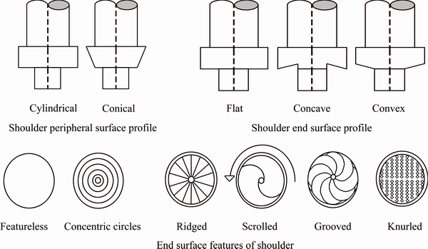
Fig. 3 Different shoulder features

Fig. 4 Commonly used tool probe shapes [8,49-52]
Shoulder-to-pin diameter ratio (SPR) defines the relation between the dimensions of tool pin and shoulder. SPR of dissimilar FSW of Al-Cu depends on the alloy type and the thickness of the workpiece. SPR is relatively high for dissimilar welding compared to similar welding. SPR range from 2:1 to 5:1 has been used by various researchers for dissimilar FSW of Al-Cu (refer to Table 3) which is quite higher than that of the similar FSW. The higher SPR used during FSW of Al-Cu (possessing different specific heats and thermal conductivities) increases the heat produced and this larger heat can be effectively distributed by controlling other process parameters, i.e., position of workpieces, tool pin offset, welding and rotational speed. During FSW of larger thickness workpiece, larger SPR is required. Designing and selection of the best suited tool pin profile is an active and needed area of research for dissimilar FSW of Al-Cu joint.
2.2 Welding speed effect during dissimilar FSW of Al-Cu
Welding speed or the traverse speed is speed through which the tool travels along the weld line of the joint. It has a significant effect on the microstructure and joint quality and its selection is a complex task for dissimilar FSW of Al-Cu [53-55]. Different welding speeds used during FSW possess quite an uncertain effect on weld properties [56]. The welding speed is needed to be carefully selected considering various factors, such as workpiece materials, joint type, rotational speed and penetration depth [57].
Development of different flow stresses during dissimilar FSW of Al-Cu is a prominent factor for weld defects. So, the identification of optimum level of welding speed is necessary in order to manage the difference in the flow stress. Heat input in the dissimilar FSW of Al-Cu is governed by the relation between the rotational and welding speed which in turn influences the IMCs formation and other mechanical properties [41]. The decrement of welding speed at constant rotational speed or the increment of rotational speed at constant welding speed possesses the similar trends with regards to weld [58]. So, it is always advisable to use the optimum combination of rotational and welding speed in order to manage the heat input and resultantly the IMCs formation during dissimilar FSW of Al-Cu [40,41,59].
It was reported that reducing the welding speed at the constant rotational speed raises the heat input to the weld zone and generates more amounts of IMCs [53-55]. At higher heat input, softened material plastically deforms and turbulent material flow occurs in the stir zone. Larger amount of IMC develops in the stir zone because of turbulent flow of softer Al while Cu particles are differently distributed in weld area. These IMCs are very hard and prone to crack formation, and resultantly, reduce the joint strength [54].
The heat input is inversely proportional to welding speed. The high welding speed produces insufficient heat input, and consequently, incomplete welded joint interface develops [53]. Lower heat input occurring at very high welding speed causes improper mixing of Al-Cu material and results in defects like voids [53-55]. Insufficient flow of material at higher welding speed results in the formation of cavities (i.e., tunneling defect) inside the joints, so by decreasing the welding speed, weld zone temperature rises and consequently reduces the flow stress, thus results in a better plastic flow of materials and less chances of a cavity defect [60]. Extremely high welding speed produces very poor metallic bonding as well [22]. For obtaining defect-free joint, low welding speed and high rotation speed are recommended [61-62].
Furthermore, the material movement occurs in two directions with respect to the tool pin. One material movement occurs in the direction of rotational speed and the other one is in the downward vertical direction [63]. Higher welding speed creates relatively cold welds and possesses less material transport in vertical direction mainly at the retreating side [64]; however, a lower welding speed results in ��hot�� welds and creates larger vertical transport at the retreating side [22,64]. But, the basic understanding of material flow behaviour at advancing and retreating side is still not well understood and requires a considerable research.
2.3 Rotational speed effect during dissimilar FSW of Al-Cu
Rotational speed is another parameter which critically affects the FSW joint quality [65]. The turning motion of the tool around the tool axis is called rotational speed and its overall contribution is 40% in dissimilar FSW of Al-Cu [30]. As mentioned previously, the FSW of Al-Cu is difficult as brittle IMCs develop in the nugget zone. Apart from the welding speed, tool rotational speed also possesses the significant effect on the reaction temperature consequently on the IMCs formation [19]. Rotational speed basically serves two purposes in dissimilar FSW as 1) affects the plastic deformation by influencing the frictional heat generation and 2) provides the adequate tool force which resultantly influences the material flow, stirred zone size, defect, IMCs formation and tool wear.
Rotational speed should be carefully selected as lower rotation speed results in less heat input and inadequate reaction temperature during FSW of dissimilar Al-Cu [28,65,66]. Due to insufficient reaction of material, appropriate plastic deformation cannot occur in stir zone. Consequently, macrocracks and channel defects are found in such cases of dissimilar FSW of Al-Cu [28,33,58,59,66]. On the other hand, higher rotation speed generates ample reaction among Al and Cu by generating high temperature in the nugget zone. But, too high rotational speed creates excessive stirring by the tool pin, which causes a large number of Cu particles to be detached from Cu bulk, too large to be distributed uniformly in weld nugget zone, consequently resulting in improper bonding and creating defect like voids and cracks [28,33,39,59,65,67].
The thick stacking layered structure of Al-Cu IMCs forms easily at high rotational speed during FSW of Al-Cu because of the large amount of detached Cu pieces presented adjacent to the interface, which causes difficulty in flowing [65]. Moreover, further increase of rotational speed increases the heat input and joint interface temperature and promotes the thickening of interfacial layer of IMCs [33,68]. The weld surface also becomes poorer with the increased rotation rates attributed to the excessive IMCs formation [28]. The high rotational speed also possesses negative impact on tool life due to excessive wear of tool by strong rubbing action [65]. So, it is necessary to identify the optimum rotational speed during FSW of dissimilar Al-Cu because both extremely low and high rotational speed results in poor mechanical and metallurgical properties [28,33,67].
3 Welding strategy for dissimilar FSW of Al-Cu
Satisfactory weld quality depends upon the strategy used to obtain the welded joints. Weld strategies as base material position, tool tilt angle and pin offset exert significant impact on the temperature distribution and material flow pattern, and thereby influence the microstructure evolution of the joint [8]. Material flow differs in advancing/retreating, top/bottom sides and strongly affects the joint configurations either butt or lap [19]. Nune��s kinematic model suggested that a straight through current flow like material flow pattern occurs at retreating side while whirlpool pattern occurs at advancing side [19]. During dissimilar FSW of Al-Cu in butt or lap configuration, the material flow around the pin is a combined effect of different welding strategies as placement of workpieces, tool pin offset and tool tilt angle. The pin is penetrated into the interface of the plates, which creates a continuous flash, and shoulder contact with the upper surface of material intensifies the flash formation. The appropriate tool tilt angle helps to flow the flashed material behind the shoulder. Friction between shoulder and top surface of material and cold deformation surrounding the pin create the heat which softens the material. The rotational speed imparts the free flow of this softens the material around the pin when the tool moves in welding direction [17]. During butt welding advancing to retreating side material flow and in the lap welding bottom to top material flow occur, respectively.
Researchers have also tried to find the effect of relative positioning of base plate, axial force, tool tilt angle and tool pin offset during dissimilar FSW of Al-Cu and it is summarized in the following section.
3.1 Workpiece material thickness
Base plate thickness is a major deciding factor for selection of particular tool design and other process parameters. A change in base plate thickness changes the stirring action, heating and cooling rate and height of weld. FSW of a thicker material using a short tool develops an improper boning adjacent to the weld root [69]. Aluminum alloys from 0.5 to 65 mm in thickness have been welded using FSW with full penetration from one side without defects like porosity and voids [70]. Al and Cu plate up to12.7 mm in thickness using FSW have been successfully joined by various researchers [26,28-31] (refer to Table 3). Further studies are needed for dissimilar FSW of Al-Cu of more than 12.7 mm in thickness.
3.2 Workpiece position and placement
Positioning of base plates at a fixed location is an critical factor during dissimilar FSW of Al-Cu unlike the conventional FSW of similar materials [26,28]. It is reported that the material flow pattern and weld quality are significantly influenced by the position and placement of base plates during FSW of dissimilar alloys [3,14,30,71,72]. If the hard material (i.e., Cu) is placed at the retreating side, it possesses resistance to move towards advancing side and results in non-uniform material flow. This non-uniform material flow among the dissimilar materials causes large volume defects such as tunnels and voids due to inappropriate mixing and also the softer material tends to extrude out from the nugget zone [28,65]. The surface tunnel is a commonly found defect while Cu is placed at retreating side and placement of Cu in advancing side contributed towards defect-free joining [28,40,42,65]. Placement of softer material at the retreating side creates a normal material flow revolution in the nugget zone and results in easy transfer of softer material towards advancing side [29,73]. So, the placement of harder Cu plate at advancing side and softer Al plate at retreating side is recommended as this forms the sound welding during dissimilar FSW of Al-Cu in butt joint configuration [28,36,40,42,62,65].
Placement of base plates during dissimilar FSW of Al-Cu in lap joint configuration is also a matter of concern as it affects the joint quality. It is recommended to place the Cu plate at bottom and Al plate at the top to achieve good quality joining. This arrangement developed suitable amount of heat in nugget zone because of lower thermal conductivity of Al and created good material flow and greater stirring, so, the sound metallurgical and defect-free joint [74].
3.3 Downward force or plunge force or axial force
Downward force or plunge force or axial force occurs in spindle axis direction and maintains the tool contact at or beneath the workpiece material. It is a very important element to control the quality of the weld obtained. Axial force is influenced by process parameters and weld strategy such as tool shoulder, welding speed, and tilt angle used during FSW [53,74]. It should be carefully maintained during FSW as lower plunge force does not provide appropriate vertical flow of plastically deformed material, while higher plunge force flashes out the deformed material. During dissimilar FSW of Al-Cu, comparatively large amount of plunge force (greater than 6 kN) (refer to Table 3) is required due to larger hardness of Cu compared to Al. Optimum plunge force is recommended during dissimilar FSW of Al-Cu as it supports complete penetration in stir zone.
3.4 Tool tilt angle
The relative position of FSW tool with the work- piece surface is known as the tool tilt angle. Positioning of FSW tool perpendicular to the workpiece is known as zero or no tilted [74]. The tool tilt angle plays an important role with respect to joint quality [75-77]. An appropriate tool tilt angle serves two purposes as 1) ensures the holding of stirred material under the shoulder by the tool pin [8] and 2) provides a uniform material flow by increasing the forging action to get proper material flow from front to back and from top to bottom under FSW tool [8,76].
It is reported that the larger tilt angle provides a tighter weld [77] and prevents the spreading of material on the top surface (i.e., flash effect). The increment of tilt angle from 0�� to 2�� during FSW of Al provided substantial changes in material flow and microstructure development [77]. FSW of AA2024 Al to pure Cu using 2�� tool tilt angle provided higher strength and good metallurgical bonding compared to 0�� tool tilt angle, because higher tilt angle with higher axial plunge force (refer to Section 3.3) provided a free flow to Cu particles in Al matrix [29]. Hardness at joint area also increases with the increment in tilt angle because of greater IMCs formation due to temperature rise in stir zone [77]. In another study of dissimilar FSW of AA6061-T651-Cu, the tilt angle from 2�� to 4�� was recommended [74]. Therefore, it is essential to identify the optimum tilt angle for FSW of Al-Cu.
3.5 Pin offset
FSW tool displacement from weld centre line toward a particular base material is known as tool pin offset. Zero or no pin offset occurs when FSW tool is positioned precisely at the centre of weld joint line. Figure 5 shows the tool and base material position for zero and 1 mm pin offset towards Al side.

Fig. 5 Schematic of tool workpiece position for pin offset
It is suggested that the conventional method of joining where pin is inserted at the weld centre line created poor and defective joints in dissimilar FSW [28,34,35,43,78]. The dissimilar materials like Al and Cu usually differ considerably in physical, chemical and mechanical properties like melting point, strength and flow stress. Due to differences in thermal conductivity and melting point, uneven and incomplete plastic deformation occurs by using zero tool pin offset during dissimilar FSW of Al-Cu. Also, the material flow situation in dissimilar FSW is completely different from that in similar FSW. Unlike similar FSW, in dissimilar FSW, the fragment of harder material acts as a barrier to material flow in stir zone. In this situation, shifting the tool towards Al side is suggested as Cu having the higher thermal expansion coefficient could not take away the larger amount of heat. This technique optimally distributes the thermal stresses to both materials and generates more heat at Al side compared to Cu side. Provision of tool pin offset towards softer material side controls the formation of fragment in the stir zone and promotes good stirring [17]. Sufficient offset distance (distance between the pin axis and joint line) of the probe towards soft materials (such that the pin just becomes tangent to the hard materials), is considered to be the most important aspect to obtain defect-free FSW joint of dissimilar materials [69]. It is widely reported that the pin offset towards the softer materials resulted in defect- free joints [21,30,36,54,62]. Provision of pin offset positively affects the material flow pattern and IMCs volume fraction, which consequently minimizes the defect and produces a sound weld in the dissimilar FSW of materials [16,79]. The maximum temperature development during FSW of Al and Cu is a function of tool pin offset [80]. Tool pin offset also helps to optimally distribute the heat generated in the materials during dissimilar FSW.
During dissimilar FSW of Al-Cu at very small tool offset, poor bonding and voids occur due to, the large number of Cu pieces which are harder than Al needed to be stirred into the nugget zone and possess difficulty in deforming and flowing in Al matrix at the prevailing welding temperature. Because of more available Cu atoms in the stirred zone at smaller tool offset, higher amount of brittle IMCs of Al-Cu develops and poor joint forms [29,81,82]. Contradictory to this, at larger pin offset, few amount of Cu pieces comparatively smaller in size are detached from the Cu bulk and easily react with Al base and mix in the nugget zone [65].
The optimum value of tool offset depends upon the base material composition, thickness, tool design and process parameters [26,28-31]. The use of 1.5-2 mm pin offset was suggested during dissimilar FSW of Al-Cu to achieve good quality joining (refer to Table 1). FSW in butt joint configuration is more uniform and defect free than lap joint configuration as uniform mixing occurs in former case while appropriate tool pin offset is provided. Tool pin offset can be adjusted by providing an extra sheet adjacent to Cu in lap joint configuration [34].
4 Microstructural analysis of dissimilar FSW Al-Cu joints
Microstructures of similar/dissimilar FSW are categorised into four zones: two microstructures outside the shoulder (parent metal microstructure, heat affected zone (HAZ)) and two microstructures under the shoulder (stir zone (SZ) and thermomechanically affected zone (TMAZ)). Dissimilar FSW of Al-Cu forms two distinct TMAZs, one at Al side and other at Al/Cu interface [74]. Microstructures obtained by various authors for dissimilar joining of Al-Cu using FSW are presented in Fig. 6.
During FSW of Al-Cu, wider TMAZ occurs at the Al side and narrower TMAZ at Al/Cu interface because the tool offset given at Al side creates more stirring at Al side and Cu grains do not get affected due to lower peak temperature at Cu side. HAZ occurs only at Al side (Fig. 6(a)), it consists of coarse and less hardened grains because of intense heat and no grain deformation occurs in this zone [33].
As per the binary equilibrium phase diagram of Al-Cu, Al4Cu9 (��2), Al2Cu3 (��), Al3Cu4 (��2), AlCu (��2) and Al2Cu (��) are the commonly found Al-Cu IMCs with the reaction between them [78]. During FSW of Al-Cu, CuAl2, Cu9Al4, Cu3Al and CuAl are the usually formed IMCs with small amounts of solid solution of Al in Cu [83] (refer to Table 3 for summary) and Al2Cu (Al-rich phase) and Al4Cu9 ( Cu-rich phase) are the firstly formed IMCs adjacent to Al and Cu side, respectively [84-88]. The material flow phenomenon is quite different in similar and dissimilar FSW as onion ring structure is commonly found in the stir zone during similar FSW [9,29], but intercalated vortex type (complex) microstructure is found in stir zone during dissimilar FSW [88]. Higher stirring action is found at bottom and it creates intercalated and swirl like pattern of material while a composite like structure occurs in the upper part of the nugget zone [89]. The irregular Cu particles appear like Cu islands in Al matrix in stir zone (Figs. 6(b, c)). Al side weld zone peak temperature is found distinctly higher compared to the melting point temperature of Al-Cu eutectic or some other hypo and hyper-eutectic alloys [30]. FSW of Al-Cu is difficult due to the formation of the hard and brittle IMCs and their presence creates uneven and fragmented defects and decreases the joint quality [33,41,58,61,65,79,90].
Continuous thin layered IMCs are usually found at the interface of Al and Cu (0.5-4 mm) (Fig. 6(d)), resulting in a sound and defect-free joining of Al-Cu [55,57,65,91], but still the Al-Cu interface region is the weakest zone due to the presence of brittle IMCs layer [53,77]. Also, the presence of IMCs critically changes the microhardness levels of the weld nugget [92]. So, the study of microstructure and IMCs formation is a needed area of concern during dissimilar FSW of Al-Cu.

Fig. 6 Microstructures for different dissimilar Cu-Al FSW systems
5 Mechanical properties of FSW of dissimilar Al-Cu
Weld joint efficiency (��), is a criterion to identify the acceptable weld joint and it is expressed as the ratio of weld tensile strength to the workpiece tensile strength. During dissimilar FSW of Al-Cu, the tensile strength of Al is considered to decide the joint efficiency because of its lower value. During dissimilar FSW of Al-Cu, the joint efficiency is reported less than 100% because of the less ultimate tensile strength (UTS) of weld joint compared to the base materials [88]. The joint efficiency is significantly influenced by the combination of rotational speed and traveling speed used during FSW of Al-Cu [93]. During dissimilar FSW of Al-Cu, the Cu side TMAZ is the weakest zone where the brittle fracture occurs during tensile testing due to hard and brittle IMCs in this zone [48,77,94-97]; however, ductile fracture occurs at Al side TMAZ because of sever plastic deformation due to comparatively fine grains in this zone [54,59,67,90,98,99]. The selection of the non-optimal process parameters is a possible region for lower UTS and weld defects due to improper material flow between Al matrix and loose Cu particles. Excessive process temperature reportedly creates larger amount of Cu particles to be diffused in Al matrix consequently larger IMCS and cracks and decreased UTS [59]. Size of Cu particle is also a very important element to affect the UTS as small size Cu particles provides strengthening and increases the UTS of joint. UTS of weld zone during dissimilar FSW of Al-Cu can be improved to some extent by providing strong stirring action. Sufficient stirring provides grain refinement, and consequently increases the UTS of weld but still less than that of the workpiece materials because of inhomogeneous microstructure and formation of IMCs. These IMCs have negative impact on the ductility, yield strength and elongation of the weld joint. The effect of traverse speed, rotational speed and pin offset on temperature generation has been reported in previous sections. UTS is propositional to rotational speed and inversely proportional to the traverse speed because this higher heat input condition generates homogeneous grains [36,56]. Larger pin offset and lower rotational speed produce poor UTS due to insufficient reaction between Cu particles and Al matrix. Higher rotational speed and appropriate pin offset of 2-2.5 mm produce high UTS during dissimilar FSW of Al-Cu [79].
Hardness also gets affected by welding temperature, strain rate and material flow [59]. It also depends on Cu particles distribution in Al matrix during FSW of Al-Cu [100]. Large number of fragmented Cu particles increases the hardness of weld nugget. The possible reason of higher hardness at any region is: 1) higher fraction of Cu in that region and 2) comparatively more homogeneous finer lamella structure in that region. FSW process parameters such as Cu particle distribution, formation of IMCs and different microstructures significantly affect the hardness at different zones. Larger heat input conditions such as larger shoulder diameter [101], lower welding speed [102] higher rotational speed [33], and larger tilt angle [77] develop higher amount of IMCs in the stir zone, consequently the higher hardness [62]. Strengthening due to Al-Cu IMCs substantially increases the hardness [65,103]. Hardness profiles given by various researchers for different dissimilar FSW are shown in Fig. 7.
The maximum hardness is observed at Al/Cu interface (stir zone) possibly due to dynamic recrystallization, grain refinement, solid solution strengthening and mechanical twinning [37,90,98]. Very fine recrystallized grains are generally found in the middle of nugget zone and maximum hardness is observed here (refer to Figs. 7(a, h-j, l) [31,74,77, 90,104]. Complex material flow critically changes the microhardness levels of the weld nugget [92]. The stir zone hardness is always higher than base materials hardness due to hard IMCs formation and considerable plastic deformation in the stir zone (refer to Figs. 7(h and j), respectively) [71,90,105,106] as per Hall-Petch effect [107]. Heterogeneous hardness distribution is found for dissimilar FSW of Al-Cu butt joint as shown in Figs. 7(b-f, i-k and n) [32,33,61,65,77,90,98,101,108]. Cu side shear zone contains higher hardness due to the presence of fine grains and IMCs layer in this area (refer to Figs. 7(c-e)) and Al side shear zone possesses considerably lower hardness even less than Al base material due to micro voids at this area [33,61,109]. However, grain coarsening at the HAZ develops the lowest hardness in this area (refer to Figs. 7(c, g, j and m) [33,73,90,108]. For similar FSW, the hardness observed across the weld section typically consists of a ����W���� shaped profile [9], for FSW of dissimilar Al-Cu in lap configuration, it consists of different profile like ����\����, as shown in Figs. 7(a, g, h, l and n) [31,73,74,104,105].
Hardness values vary not only in different zones but also from top to bottom in stir zone during for butt joining (refer to Figs. 7(e, j and k)). More amount of IMCs are presented at bottom of stir zone and consequently higher hardness is observed here (refer to Figs. 7(e and k), respectively) [65,98] but it is contradictory to ESMAEILI et al [32] (refer to Fig. 7(d)). Reduction of hardness in stir zone is a prominent area of research during dissimilar FSW of Al-Cu.
6 Electrical and chemical analysis of dissimilar FSW of Al-Cu
Most of the components made by joining Al and Cu are required to be highly conductive, so the electrical properties of the dissimilar FSW of Al-Cu joint are a major area of concern. Joint��s electrical resistivity is proportional to the heat input and increases with its increment [82,101]. Dissimilar materials may be successfully welded with excellent joint integrity as it is reported that during FSW of 5754 Al and C11000 Cu the increase in the electrical resistivity is lower in the welds compared to the parent materials [37]. The corrosion results of dissimilar joints of Al-Cu made by using FSW revealed that traverse speed does not have the major influence on the rate of corrosion, however, rotational speed majorly influences the rate of corrosion. Higher rotational speed creates more amount of Al2Cu intermetallics which increases the corrosion resistance [110].

Fig. 7 Hardness distribution for FSW of different dissimilar Al-Cu alloys
7 Welding defects of dissimilar FSW of Al-Cu
Non-optimal FSW process parameters and incorrect welding strategy cause the several weld defects [91,105]. Radiographic testing is a reliable approach to detect any hidden internal defect of the joints fabricated by FSW [111]. Most of the welding defects found during dissimilar FSW of Al-Cu are shown in Fig. 8.
7.1 Cavity/voids and tunnel
Cavities/voids are volumetric defects where empty space containing no material is created and usually occurs at advancing side of the joint. The presence of void above the root and beneath the top surface in continuous pattern is more commonly known as tunneling defect. Selection of non-optimal FSW process parameters results in insufficient heat input and material flow and void/cavity forms in the joints. Too low rotational speed/too high traverse speed, and too low plunge load are the various reasons for developing voids [91]. Lower welding speed decreases the chances of cavity/void formation by increasing the weld zone temperature, and resultantly decreases the flow stress and creates good plastic flow [60]. But higher welding speed promotes this type of defect and produces very poor metallic bonding as well [22]. Thus, lower welding speed or higher rotational speed is recommended for reducing the chances of void and cavity formation.

Fig. 8 Common welding defects in FSW of dissimilar Al-Cu
Base plates positioning and tool pin offset during dissimilar FSW are dominant factors towards cavity/void formation apart from tool design and configuration, and axial pressure [17]. As discussed before, the Cu plate should be placed at advancing side, otherwise transfer of hard Cu particle to the advancing side becomes difficult and continuous void (connected tunnel) defect forms in the weld; however, placing of Cu plate at advancing side creates defect free welds [28]. It has been reported that smaller shoulder diameter and larger pin offset promote the tunnel defect [38,112]. Lower pin offset and placement of Cu at retreating side create large void and connected tunnel because large amount of Al extrudes out from weld zone [28,43,65]. Selection of optimum pin offset during dissimilar FSW reduces the voids and tunnel defects. Tool pin profile also possesses significant effect during dissimilar FSW of Al-Cu as taper pin profile creates voids in the bottom part of the stir zone due to inadequate mixing of Al and Cu in this zone [112]. Figures 8(a), (c) and (d) represent the voids occurred at stir zone of Al-Cu.
7.2 Macrocrack and microcrack
Crack formation is another defect which is visible on the weld surface. Insufficient plunge depth, improper tool design and pin offset and incorrect positioning of base plates are prime causes for crack development [17,28,91,112]. Cracks may be further considered as macrocracks and microcracks and these are dominantly found in stir zone during dissimilar FSW of Al-Cu, as presented in Figs. 6(b), (d), and (e). IMCs formation and poor metallurgical bonding in the stir zone are the possible reasons of cracks in this area (refer to Figs. 8(b and d)) [28,54,112].
7.3 Fragmented defects
Fragmented defects are uniquely found during dissimilar FSW of Al-Cu and generally do not appear for similar FSW. The fragmented Cu particles in the aluminium matrix are considered as fragmented defect. The inappropriate material flow cannot distribute the fragmented Cu uniformly, thus the contacting surface of fragments and sharp edges remains unfilled and causes voids, microcracks due to higher hardness and lower tensile strength in stir zone. Selection of the optimal process parameters especially the lower rotational speed and appropriate tool pin offset can reduce these defects [17].
7.4 Lack of penetration
Lack of penetration is another commonly found weld defect during dissimilar FSW. This occurs at the bottom of the welded joint where workpieces are detached or not joined properly which results in weak bonding. This may be considered a crack where high stress corrosion factor, low tensile strength and poor fatigue strength occur and lead to fracture. Welding conditions like improper tool design, too short tool pin, too low plunge depth, variation in plate thickness or misalignment of the tool with respect to the butting surfaces increases this kind of defect. This defect may be detected by using a bend test where root is under the tension [112].
7.5 Pores
The larger size voids, 0.1-0.5 mm in diameter are considered as pores and usually found in the stir zone. These may be seen as single or in line up to 9 mm in length. Too small tool plunge depth [112], small tool tilt angle [38,74,91] and very low rotational speed [113] are the main identified welding parameters causing pores in stir zone.
8 Alternates of dissimilar FSW of Al-Cu alloys
FSW technology has been developed and improved using different approaches and methods for dissimilar Al-Cu system. Friction stir spot welding (FSSW), under water friction stir welding (UFSW), FS lap welding using intermediate layer, friction stir butt barrier welding (FSBBW), friction stir diffusion bonding (FSDB), cold rolling post FSW, hybrid FSW (HFSW), warm friction stir welding (WFSW), friction stir brazing (FSB), and microfriction stir spot welding (��FSW) are the different modified and alternative FSWs for dissimilar Al-Cu system and are discussed here as alternates of the technology.
FSSW has been successfully used to join Al-Cu alloys. FSSW of AA6061-T6 Al and Cu of 1.5 mm thick sheets, placing Al above the Cu sheet resulted in good weld strength as 2090 N with the use of 2.60 mm pin length, 0.13 mm plunge depth, 2000 r/min rotational speed and 3 s weld time [9,114]. The similar kind of study for FSSW of AA5083 Al and deoxidized phosphorous Cu led to the development of the 10 mm fine composite band layer of fine particles at the Al-Cu joint interface [115]. In a study of FSSW of 1050 Al alloy and pure Cu using three different plunge depths of 2.8, 4 and 5 mm reported the defect free joint with good tensile property using 4 mm and 5 mm plunge depth. Recrystallization and grain deformation in the stir zone resulted in finer grains at Cu side near to the Al/Cu interface in compared to the base material Cu [116]. FSSW of Al/Cu composite using a triangular pin through accumulative roll bonding technique recommended the use of higher tool rotational speed to increase the maximum shear failure load [117]. FSSW of 1060 Al alloy and pure Cu by placing Al above the Cu developed the Cu ring of various lengths on both sides of the welded joints, which provides the strong welds due to the extrusion of Cu upward into Al sheets [118].
UFSW creates horizontal and vertical material flow simultaneously, but FSW creates only horizontal material flow. It is reported that the UFSW created horizontal material flow, prevented oxidation of base materials, reduced IMCs formation and decreased the peak temperature during joining of AA6061-T6 Al and pure Cu while similar process parameters were used [119]. Figure 9 shows the horizontal and vertical material flow around the tool.
FS lap welding using intermediate layer is also found effective during joining of Al-Cu. Use of a new anodized material Al-MIL-A-8625F containing coating of anodic sulfur with a layer of 23 mm-thick Cu improved the shear strength by 25% and prevented the IMCs formation during dissimilar FSW of AA6060 Al and Cu [120]. Similar kind of study that used the 50 mm-thick Zn intermediate layer during dissimilar FSW of AA1100-H24 Al and pure Cu also reported the good metallurgical bonding and limited IMCs formation [121].

Fig. 9 Material flow
Use of barrier sheet during FSW is also found effective sometimes. FSBBW of dissimilar AA5052 to Cu using AA5052 as barrier layer improved surface appearance and eliminated cracks, pits, grooves and flashes. Increment of barrier sheet up to a certain thickness creates a better welding conditions but the use of Cu sheet as barrier layer is not recommended [122]. FSBBW also increased the productivity as welding speed got doubled with this joint configuration [35]. Barrier welding can also be used in lap joint configuration while barrier layer of Al should be placed near to Cu as it helps to provide an appropriate tool pin offset and results in a better weld quality [34].
FSDB is also an improved alternate of FSW to join dissimilar Al-Cu where the tool pin is completely inserted into the Al sheet resulting in joining through frictional heating and stirring causing the interfacial chemical reaction without any mechanical mixing. But, inter diffusion reaction cannot prevent the formation of IMCs and leads to poor tensile strength [123,124].
HFSW/WFSW has great potential in preparing defect-free joint of dissimilar materials like Al and Cu. Preheating of FSW Al-Cu joints enhances the mechanical properties as preheating increases the hardness at Cu side [125]. Preheating of Cu side up to 200 ��C develops adequate material flow around the tool, prevents excessive IMCs formation and improves the weld quality of dissimilar FSW of Al-Cu [126]. The use of a separate FS tool as a preheating source to raise the temperature of Cu sheet by 150-200 ��C in HFSW of AA5A06 Al and Cu-T2, resulted in 230 MPa maximum tensile strength and improved weld efficiency [48]. Plasma torch has been also used as preheating source in HFSW of dissimilar AA1000 and Cu to preheat the Cu side to 200 ��C, and improvement in weld efficiency was reported [127].
Cold rolling post FSW is also found effective to improve the mechanical properties and to remove weld defects like flaws. Cold rolling post FSW creates strain hardening effect in the dissimilar materials and results into huge rises in tensile strength. Also, the cold rolling can apart the IMCs layer to eliminate various defects like voids and cracks. FSW of 0.5 mm initially thick sheets of AA1100-C11000 was followed by cold rolling and 70 ��m of thickness was obtained without flaws [128]. Also, the FSW of ultra thin thickness of 0.8 mm of AA5051-pure Cu has been done without IMCs formation [129]. HFSW of dissimilar AA6063-T6 and soft-annealed DHP Cu followed by cold rolling resulted in 50% more joint efficiency compared to the base materials [130].
FSB method used to join Al-Cu is found much more effective than conventional brazing process. In a FSB study, 0.1 mm-thick Zn foil was placed between the Al-Cu sheets and a pin, less tool was moved on the workpieces and this resulted in excellent joining compared to the furnace brazing. Failure load of the joint was also higher than that of the conventional lap joint configuration [131]. FSB of 1A99 Al and pure Cu using Zn intermediate layer also reduced the IMCs formation and produced good mechanical properties [132].
��FSSW is used to join the material thicknesses of 1000 ��m or less. ��FSSW improved the strength, electrical resistivity and reduced the formation of IMCs while C connector of Al and Cu cable was joined [133].
9 Conclusions and scope for future research
A comprehensive review of the available literature on dissimilar FSW of aluminum to copper has been presented to provide insight for the current state of the art knowledge related to dissimilar FSW of Al-Cu. Most of the referred research studies provided a deep understanding of the various process parameters and their influence on the microstructure, mechanical and electrical properties of the Al-Cu joints made by FSW. The defects that occurred during dissimilar FSW of Al-Cu found by researchers are listed and their possible causes and remedies have been discussed. In addition, other possible variants of FSW used by researchers for dissimilar FSW of Al-Cu are discussed. Despite considerable research interests in the dissimilar FSW of Al-Cu, complete fundamental understanding to join these materials is still lacking and therefore, following suggestions are proposed for future investigations.
1) The material flow pattern, tool geometry and design, welding tool wear, microstructural stability are very important aspects which require more understanding for joining Al-Cu using FSW and therefore, these aspects may be explored.
2) The holistic studies on thrust force and other force component as well as torque empowered for FSW of Al-Cu remains under reported. Consequently, investigations may be carried out to measure these performance parameters.
3) Considerable scope exists for analyzing heat input, heat balance, flow stress on both sides i.e. advancing/retreating and top/bottom sides. Further, temperature distribution coupled with flow stress under various deleterious condition are formed which needs special attention in future studies.
4) New studies need to be carried out for process optimization and cost effective FSW tools selection for good quality joining. The improvement in this technique is a much needed area of research for employing this for industrial application to join dissimilar materials.
References
[1] SINGH H, ARORA H. Friction stir welding-Technology and future potential [C]//Proceedings of National Conference on Advancements and Futuristic Trends in Mechanical and Materials Engineering. Tangori, Mohali, Punjab, India, 2010: 32-38.
[2] BRAUNOVI��C M, ALEKSANDROV N. Effect of electrical current on the morphology and kinetics of formation of intermetallic phases in bimetallic aluminum-copper joints [C]//Proceedings of the Thirty-Ninth IEEE Holm Conference on Electrical Contacts. Pittsburgh, Pennsylvania: IEEE, 1993: 261-268.
[3] ABBASI M, TAHERI A K, SALEHI M. Growth rate of intermetallic compounds in Al/Cu bimetal produced by cold roll welding process [J]. Journal of Alloys and Compounds, 2001, 319(1): 233-241.
[4] MUBIAYI M, AKINLABI E. Friction stir welding of dissimilar materials between aluminium alloys and copper, An overview [C]//Proceedings of the World Congress on Engineering. San Francisco, USA: IAENG Publications, 2013: 3-5.
[5] BERGMANN J P, PETZOLDT F, SCH��URER R, SCHNEIDER S. Solid-state welding of aluminum to copper��Case studies [J]. Welding in the World, 2013, 57(4): 541-550.
[6] OKAMURA H, AOTA K. Joining of dissimilar materials with friction stir welding [J]. Welding International, 2004, 18(11): 852-860.
[7] THOMAS W M, NICHOLAS E D, NEEDHAM J C, MURCH M G, TEMPLE-SMITH P, DAWES C J. Friction welding [P]. US Patent 5460317. 1991.
[8] MISHRA R S, MA Z. Friction stir welding and processing [J]. Materials Science and Engineering R: Reports, 2005, 50(1): 1-78.
[9] LIENERT T, MISHRA R, MAHONEY M. Friction stir welding and processing [M]. Materials Park, OH: ASM International, 2007: 123-154.
[10] NANDAN R, DEBROY T, BHADESHIA H. Recent advances in friction-stir welding�Cprocess, weldment structure and properties [J]. Progress in Materials Science, 2008, 53(6): 980-1023.
[11] THOMAS W, NORRIS I, STAINES D, WATTS E. Friction stir welding��Process developments and variant techniques [J]. The SME Summit, 2005, 1(1): 1-21.
[12] LOHWASSER D, CHEN Z. Friction stir welding: From basics to applications [M]. New York, USA: Elsevier, 2009.
[13] GIBSON B, LAMMLEIN D H, PRATER T, LONGHURST W, COX C, BALLUN M, DHARMARAJ K J, COOK G E, STRAUSS A M. Friction stir welding: Process, automation, and control [J]. Journal of Manufacturing Processes, 2014, 16(1): 56-73.
[14] DEBROY T, BHADESHIA H. Friction stir welding of dissimilar alloys��A perspective [J]. Science and Technology of Welding & Joining, 2010, 15(4): 266-270.
[15] SAVOLAINEN K, MONONEN J, SAUKKONEN T. A preliminary study on friction stir welding of dissimilar metal joints of copper and aluminium [C]//Proceedings of 6th International Symposium on Friction Stir Welding. Saint-Sauveur, Canada: Emerald Group Publishing Limited, 2005: 10-13.
[16] MEILINGER A, TOROK I. The importance of friction stir welding tool [J]. Production Processes and Systems, 2013, 6(1): 25-34.
[17] ESMAEILI A, BESHARATI G M, ZAREIE R H. Experimental investigation of material flow and welding defects in friction stir welding of aluminum to brass [J]. Materials and Manufacturing Processes, 2012, 27(12): 1402-1408.
[18] ZHANG Y, CAO X, LAROSE S, WANJARA P. Review of tools for friction stir welding and processing [J]. Canadian Metallurgical Quarterly, 2012, 51(3): 250-261.
[19] OUYANG J, KOVACEVIC R. Material flow and microstructure in the friction stir butt welds of the same and dissimilar aluminum alloys [J]. Journal of Materials Engineering and Performance, 2002, 11(1): 51-63.
[20] MURR L, FLORES R, FLORES O, MCCLURE J, LIU G, BROWN D. Friction-stir welding: Microstructural characterization [J]. Material Research Innovations, 1998, 1(4): 211-223.
[21] LEE W B, JUNG S B. Void free friction stir weld zone of the dissimilar 6061 aluminum and copper joint by shifting the tool insertion location [J]. Materials Research Innovations, 2004, 8(2): 93-96.
[22] SAEID T, ABDOLLAH-ZADEH A, SAZGARI B. Weldability and mechanical properties of dissimilar aluminum�Ccopper lap joints made by friction stir welding [J]. Journal of Alloys and Compounds, 2010, 490(1): 652-655.
[23] Friction stir welding-Technical Handbook [M]. Swedan: ESAB Publisher, 2011.
[24] SHAH S, TOSUNOGLU S. Friction stir welding: current state of the art and future prospects [C]//16th World Multi-Conference on Systemics, Cybernetics and Informatics. Orlando, Florida, 2012: 17-20.
[25] RAI R, DE A, BHADESHIA H, DEBROY T. Review: Friction stir welding tools [J]. Science and Technology of Welding and Joining, 2011, 16(4): 325-342.
[26] AGARWAL S P, NAGESWARAN P, ARIVAZHAGAN N, RAMKUMAR K D. Development of friction stir welded butt joints of AA 6063 aluminium alloy and pure copper [C]//International Conference on Advanced Research in Mechanical Engineering. Uttarakhand, India: IPM rt. Ltd Naintal, 2012: 46-50.
[27] FUJII H, CUI L, MAEDA M, NOGI K. Effect of tool shape on mechanical properties and microstructure of friction stir welded aluminum alloys [J]. Materials Science and Engineering A, 2006, 419(1): 25-31.
[28] XUE P, NI D, WANG D, XIAO B, MA Z. Effect of friction stir welding parameters on the microstructure and mechanical properties of the dissimilar Al-Cu joints [J]. Materials Science and Engineering A, 2011, 528(13): 4683-4689.
[29] TOLEPHIH M H, MAHMOOD H M, HASHEM A H, ABDULLAH E T. Effect of tool offset and tilt angle on weld strength of butt joint friction stir welded specimens of AA2024 aluminum alloy welded to commercial pure cupper [J]. Chemistry and Materials Research A, 2013, 3(4): 49-58.
[30] OUYANG J, YARRAPAREDDY E, KOVACEVIC R. Microstructural evolution in the friction stir welded 6061 aluminum alloy (T6-temper condition) to copper [J]. Journal of Materials Processing Technology, 2006, 172(1): 110-122.
[31] SHOJAEEFARD M H, KHALKHALI A, AKBARI M, TAHANI M. Application of Taguchi optimization technique in determining aluminum to brass friction stir welding parameters [J]. Materials & Design, 2013, 52: 587-592.
[32] ESMAEILI A, GIVI M B, RAJANI H Z. A metallurgical and mechanical study on dissimilar Friction Stir welding of aluminum 1050 to brass (CuZn30) [J]. Materials Science and Engineering A, 2011, 528(22): 7093-7102.
[33] ESMAEILI A, RAJANI H Z, SHARBATI M, GIVI M B, SHAMANIAN M. The role of rotation speed on intermetallic compounds formation and mechanical behavior of friction stir welded brass/aluminum 1050 couple [J]. Intermetallics, 2011, 19(11): 1711-1719.
[34] FIROUZDOR V, KOU S. Al-to-Cu friction stir lap welding [J]. Metallurgical and Materials Transactions A, 2012, 43(1): 303-315.
[35] BABU A S, DEVANATHAN C. An overview of friction stir welding [J]. International Journal of Research in Mechanical Engineering and Technology, 2013, 3(2): 259-265.
[36] SINGH S H, MAHMEEN M. Effect of tool pin offset on the mechanical properties of dissimilar materials based on friction stir welding (FSW) [J]. International Journal of Modern Trends in Engineering and Research, 2016, 3: 75-80.
[37] AKINLABI E. Effect of shoulder size on weld properties of dissimilar metal friction stir welds [J]. Journal of Materials Engineering and Performance, 2012, 21(7): 1514-1519.
[38] MEHTA, KUSH P, BADHEKA V. Experimental investigation of process parameters on defects generation in copper to AA6061-T651 friction stir welding [J]. International Journal of Advances in Mechanical and Automobile Engineering, 2016, 3: 55-58.
[39] TSUTOMU T, TAIKI M, TOMOTAKE H. Comprehensive analysis of joint strength for dissimilar friction stir welds of mild steel to aluminum alloys [J]. Scripta Materialia, 2009, 61: 756-759.
[40] GALVAO I, LEAL R, LOUREIRO A, RODRIGUES D. Material flow in heterogeneous friction stir welding of aluminium and copper thin sheets [J]. Science and Technology of Welding & Joining, 2010, 15(8): 654-660.
[41] GALVAO I, OLIVEIRA J, LOUREIRO A, RODRIGUES D. Formation and distribution of brittle structures in friction stir welding of aluminium and copper: Influence of process parameters [J]. Science and Technology of Welding and Joining, 2011, 16(8): 681-689.
[42] GALVAO I, VERDERA D, GESTO D, LOUREIRO A, RODRIGUES D. Analysing the challenge of aluminum to copper FSW [C]//Proceedings of 9th International Symposium on Friction Stir Welding. AIMEN, Relva 27A Torneiros, 36410. 2012: 1-17.
[43] GALVAO I, LOUREIRO A, VERDERA D, GESTO D, RODRIGUES D. Influence of tool offsetting on the structure and morphology of dissimilar aluminum to copper friction-stir welds [J]. Metallurgical and Materials Transactions A, 2012, 43(13): 5096-5105.
[44] GALVAO I, VERDERA D, GESTO D, LOUREIRO A, RODRIGUES D. Influence of aluminium alloy type on dissimilar friction stir lap welding of aluminium to copper [J]. Journal of Materials Processing Technology, 2013, 213(11): 1920-1928.
[45] GALVAO I,  C, LOUREIRO A, RODRIGUES D. Study of the welding conditions during similar and dissimilar aluminium and copper welding based on torque sensitivity analysis [J]. Materials & Design, 2012, 42: 259-264.
[46] OOSTERKAMP A, OOSTERKAMP L D, NORDEIDE A. ��Kissing bond�� phenomena in solid-state welds of aluminum alloy [J]. Welding Journal, 2004, 83(8): 225-231.
[47] PATIL H, SOMAN S. Experimental study on the effect of welding speed and tool pin profiles on AA6082-O aluminium friction stir welded butt joints [J]. International Journal of Engineering, Science and Technology, 2010, 2(5): 268-275.
[48] ZHAO X, DONG F B, SU G Y, GUO L J. Weld quality improvement with hybrid FSW technology assisted by preheating for copper T2/aluminium 5A06 dissimilar materials [J]. Applied Mechanics and Materials, 2012, 121: 1707-1711.
[49] SUN N, YIN Y, GERLICH A, NORTH T. Tool design and stir zone grain size in AZ31 friction stir spot welds [J]. Science and Technology of Welding & Joining, 2009, 14(8): 747-752.
[50] ROWE C, THOMAS W M. Advances in tooling materials for friction stir welding [M]. Essex, UK: TWI and Cedar Metals Ltd, 2005: 1-11.
[51] COLEGROVE PA, SHERCLIFF H. Development of Trivex friction stir welding tool Part 2�CThree-dimensional flow modeling [J]. Science and Technology of Welding & Joining, 2004, 9(4): 352-361.
[52] THOMAS W M, JOHNSON K I, WIESNER C S. Friction stir welding-Recent developments in tool and process technologies [J]. Advanced Engineering Materials, 2003, 5: 485-490.
[53] AKINLABI E T, ELS-BOTES A, MCGRATH P J. Effect of travel speed on joint properties of dissimilar metal friction stir welds [C]// Proceedings of 2nd International Conference on Advances in Engineering and Technology (AET). Uganda, 2011: 155-161.
[54] FOTOUHI Y, RASAEE S, ASKARI A, BISADI H. Effect of transverse speed of the tool on microstructure and mechanical properties in dissimilar butt friction stir welding of Al5083�Ccopper sheets [J]. Engineering Solid Mechanics, 2014, 2(3): 239-246.
[55] MUTHU MFX, JAYABALAN V. Tool travel speed effects on the microstructure of friction stir welded aluminum�Ccopper joints [J]. Journal of Materials Processing Technology, 2015, 217: 105-113.
[56] SAKTHIVEL T, SENGAR G, MUKHOPADHYAY J. Effect of welding speed on microstructure and mechanical properties of friction-stir-welded aluminum [J]. The International Journal of Advanced Manufacturing Technology, 2009, 43(5-6): 468-473.
[57] ERICSSON M,  R. Influence of welding speed on the fatigue of friction stir welds, and comparison with MIG and TIG [J]. International Journal of Fatigue, 2003, 25(12): 1379-1387.
[58] ABDOLLAH-ZADEH A, SAEID T, SAZGARI B. Microstructural and mechanical properties of friction stir welded aluminum/copper lap joints [J] Journal of Alloys and Compounds, 2008, 460(1): 535-538.
[59] BISADI H, TAVAKOLI A, SANGSARAKI M T, SANGSARAKI K T. The influences of rotational and welding speeds on microstructures and mechanical properties of friction stir welded Al5083 and commercially pure copper sheets lap joints [J]. Materials & Design, 2013, 43: 80-88.
[60] KIM Y, FUJII H, TSUMURA T, KOMAZAKI T, NAKATA K. Three defect types in friction stir welding of aluminum die casting alloy [J]. Materials Science and Engineering A, 2006, 415(1): 250-254.
[61] GENEVOIS C, GIRARD M, HUNEAU B, SAUVAGE X, RACINEUX G. Interfacial reaction during friction stir welding of Al and Cu [J]. Metallurgical and Materials Transactions A, 2011, 42(8): 2290-2295.
[62] GIHAD K, MERAH N, SHUAIB A, BADOUR F, BAZOUNE A. Experimental and numerical investigations of friction stir welding of aluminum to copper [M]//Applied Mechanics, Behavior of Materials, and Engineering Systems. Springer International Publishing, 2017: 129-138.
[63] JI S, XING J, YUE Y, MA Y, ZHANG L, GAO S. Design of friction stir welding tool for avoiding root flaws [J]. Materials, 2013, 6(12): 5870-5877.
[64] CEDERQVIST L, REYNOLDS A. Factors affecting the properties of friction stir welded aluminum lap joints [J]. Welding Journal, 2001, 80(12): 281-288s.
[65] BARCELLONA A, BUFFA G, FRATINI L. Process parameters analysis in friction stir welding of AA6082-T6 sheets [C]//Proceeding of Esaform Conference on Material Forming 2004. Trondheim, Norway, 2004: 371-374.
[66] WATANABE T, TAKAYAMA H, YANAGISAWA A. Joining of aluminum alloy to steel by friction stir welding [J]. Journal of Materials Processing Technology, 2006, 178(1): 342-349.
[67] BISADI H, RASAEE S, FOTOOHI Y. Studying of tool rotation speed on mechanical properties of copper�CAl5083 butt joint welded by friction stir welding [J]. Proceedings of the Institution of Mechanical Engineers, Part B: Journal of Engineering Manufacture, 2015, 229(10): 1734-1741.
[68] FOTOOHI Y, RASAEE S, BISADI H, ZAHEDI M. Effect of friction stir welding parameters on the mechanical properties and microstructure of the dissimilar Al5083�Ccopper butt joint [J]. Proceedings of the Institution of Mechanical Engineers, Part L: Journal of Materials Design and Applications, 2014, 228(4): 334-340.
[69] AL-JARRAH J A. Surface morphology and mechanical properties of aluminum-copper joints welded by friction stir welding [D]. Jordan: Al-Balqa Applied University, 2014.
[70] KALLGREN T. Friction stir welding of copper canisters for nuclear waste [M]. Stockholm: KTH, 2005: 1-51.
[71] FIROUZDOR V, KOU S. Al-to-Mg friction stir welding: Effect of material position, travel speed, and rotation speed [J]. Metallurgical and Materials Transactions A, 2010, 41(11): 2914-2935.
[72] XUE P, XIAO B L, WANG D, MA Z. Achieving high property friction stir welded aluminium/copper lap joint at low heat input [J]. Science and Technology of Welding and Joining, 2011, 16(8): 657-661.
[73] BEYGI R, KAZEMINEZHAD M, KOKABI A. Butt joining of Al-Cu bilayer sheet through friction stir welding [J]. Transactions of Nonferrous Metals Society of China, 2012, 22(12): 2925-2929.
[74] AKBARI M, ABDI BEHNAGH R, DADVAND A. Effect of materials position on friction stir lap welding of Al to Cu [J]. Science and Technology of Welding and Joining, 2012, 17(7): 581-588.
[75] ARICI A, SELALE S. Effects of tool tilt angle on tensile strength and fracture locations of friction stir welding of polyethylene [J]. Science and Technology of Welding and Joining, 2007, 12(6): 536-539.
[76] BOZKURT Y, KENTLI A, UZUN H, SALMAN S. Experimental investigation and prediction of mechanical properties of friction stir welded aluminium metal matrix composite plates [J]. Materials Science, 2012, 18(4): 336-340.
[77] MEHTA K P, BADHEKA V. Effects of tilt angle on the properties of dissimilar friction stir welding copper to aluminum [J].Materials and Manufacturing Processes, 2016, 31(3): 255-263.
[78] AKINLABI E T, ELS-BOTES A, LOMBARD H. Effect of tool displacement on defect formation in friction stir welding of aluminium and copper [C]//Proceedings of the 8th International Friction Stir Welding Symposium. Hamburg, Germany, TWI Ltd, 2010: 216-224.
[79]  M, TAILLARD R, JI G, GORAN D. Multiscale study of interfacial intermetallic compounds in a dissimilar Al 6082-T6/Cu friction-stir weld [J]. Metallurgical and Materials Transactions A, 2012, 43(12): 4655-4666.
[80] AALAMI-ALEAGHA M E, HADI B, SHAHBAZI M A. 3-dimensional numerical analysis of friction stir welding of copper and aluminum [J]. Journal of Mechanical Science and Technology, 2016, 30(8): 3767-3776.
[81] PANDE S V, BADHEKA V J. Effect of tool pin offset on mechanical and metallurgical properties of dissimilar FSW joints of 6061T6 Al alloy to copper material [J]. Indian Welding Journal, 2014, 47(3): 1-7.
[82] ELREFAEY A, TAKAHASHI M, IKEUCHI K. Microstructure of aluminum/copper lap joint by friction stir welding and its performance [J]. Journal of High Temperature Society, 2004, 30(5): 286-292.
[83] MURR L, LI Y, FLORES R, TRILLO E A, MCCLURE J. Intercalation vortices and related microstructural features in the friction-stir welding of dissimilar metals [J]. Material Research Innovations, 1998, 2(3): 150-163.
[84] AKINLABI E T, AKINLABI S A. Effect of heat input on the properties of dissimilar friction stir welds of aluminium and coppe [J]. American Journal of Materials Science, 2012, 2(5): 147-152.
[85] FUNAMIZU Y, WATANABE K. Interdiffusion in the Al-Cu system [J]. Transactions of the Japan Institute of Metals, 1971, 12(3): 147-152.
[86] SAVOLAINEN K. Friction stir welding of copper and microstructure and properties of the welds [D]. Espoo, Finland: Aalto University, 2012.
[87] CHEN C Y, CHEN H L, HWANG W S. Influence of interfacial structure development on the fracture mechanism and bond strength of aluminum/copper bimetal plate [J]. Materials Transactions, 2006, 47(4): 1232-1239.
[88] JIANG H, DAI J, TONG H, DING B, SONG Q, HU Z. Interfacial reactions on annealing Cu/Al multilayer thin films [J]. Journal of Applied Physics, 1993, 74(10): 6165-6169.
[89] PENG X, WUHRER R, HENESS G, YEUNG W. On the interface development and fracture behaviour of roll bonded copper/ aluminium metal laminates [J]. Journal of Materials Science, 1999, 34(9): 2029-2038.
[90] TAN C, JIANG Z, LI L, CHEN Y, CHEN X. Microstructural evolution and mechanical properties of dissimilar Al-Cu joints produced by friction stir welding [J]. Materials & Design, 2013, 51: 466-473.
[91] XUE P, XIAO B, NI D, MA Z. Enhanced mechanical properties of friction stir welded dissimilar Al-Cu joint by intermetallic compounds [J]. Materials Science and Engineering A, 2010, 527(21): 5723-5727.
[92] SINGH R K R, PRASAD R, PANDEY S. Mechanical properties of friction stir welded dissimilar metals [C]/Proceedings of the National Conference on Trends and Advances in Mechanical Engineering. 2012: 579-583.
[93] BHATTACHARYA T K, DAS H, PAL T K. Influence of welding parameters on material flow, mechanical property and intermetallic characterization of friction stir welded AA6063 to HCP copper dissimilar butt joint without offset [J]. Transactions of Nonferrous Metals Society of China, 2015, 25(9): 2833-46.
[94] LIU H, SHEN J, ZHOU L, ZHAO Y, LIU C, KUANG L. Microstructural characterisation and mechanical properties of friction stir welded joints of aluminium alloy to copper [J]. Science and Technology of Welding and Joining, 2011, 16(1): 92-98.
[95] AKINLABI E T. Characterisation of dissimilar friction stir welds between 5754 aluminium alloy and C11000 copper [D]. 2011.
[96] AKINLABI E T, AKINLABI S A. Fracture location characterizations of dissimilar friction stir welds [J]. International Journal of Mechanical, Industrial Science and Technology, 2011, 11(5): 1221-1225.
[97] WAHID M A, SIDDIQUEE A N, KHAN Z A, ASJAD M. Friction stir welds of Al alloy-Cu: An investigation on effect of plunge depth [J]. Archive of Mechanical Engineering, 2016, 63(4): 619-634.
[98] LI X W, ZHANG D T, CHENG Q, ZHANG W. Microstructure and mechanical properties of dissimilar pure copper/1350 aluminum alloy butt joints by friction stir welding [J]. Transactions of Nonferrous Metals Society of China, 2012, 22(6): 1298-1306.
[99] SARRAFI R. Evaluation of microstructure and mechanical properties of aluminum to copper friction stir butt welds [J]. Friction Stir Welding and Processing VI, 2011, 253-264.
[100] RAJANI H Z, ESMAEILI A, MOHAMMADI M, SHARBATI M, GIVI M. The role of metal-matrix composite development during friction stir welding of aluminum to brass in weld characteristics [J]. Journal of Materials Engineering and Performance, 2012, 21(11): 2429-2437.
[101] XUE P, XIAO B, ZONQYI M. Microstructure and mechanical properties of friction stir welded dissimilar Al-Cu thin plate joints [C]//10th International Symposium on Friction Stir Welding. Beijing, China: TWI Ltd, 2014: 754-761.
[102] LIU P, SHI Q, WANG W, WANG X, ZHANG Z. Microstructure and XRD analysis of FSW joints for copperT2/aluminium 5A06 dissimilar materials [J]. Materials Letters, 2008, 62(25): 4106-4108.
[103] SARE C,CAKIR R. Effect of friction stir welding parameters on the mechanical and microstructure properties of the Al-Cu butt joint [J]. Metals, 2016, 6(6): 1-15.
[104] GUPTA M S N, BALUNAIK B, MURTI K. Finite element modeling and thermo-mechanical analysis of friction stir welded Al/Cu bimetallic lap joints [J]. International Journal of Mechanical Engineering and Robotics Research, 2012, 2(17): 165-173.
[105] AKBARI M, BEHNAGH R A. Dissimilar friction-stir lap joining of 5083 aluminum alloy to CuZn34 brass [J]. Metallurgical and Materials Transactions B, 2012, 43(5): 1177-1186.
[106] ZHANG Q Z, GONG W B, WEI L. Microstructure and mechanical properties of dissimilar Al-Cu joints by friction stir welding [J]. Transactions of Nonferrous Metals Society of China, 2015, 5(6): 1779-1786.
[107] AKINLABI E T, MADYIRA D, AKINLABI S A. Effect of heat input on the electrical resistivity of dissimilar friction stir welded joints of aluminium and copper [C]//Proceeding of IEEE Africon. Livingstone, Zambia: IEEE, 2011: 1-4.
[108] AL-ROUBAIY A O, NABAT SM, BATAKO A D. Experimental and theoretical analysis of friction stir welding of Al-Cu joints [J]. The International Journal of Advanced Manufacturing Technology, 2014, 71(9-12): 1631-1642.
[109] MUTHU M F, JAYABALAN V. Effect of pin profile and process parameters on microstructure and mechanical properties of friction stir welded Al-Cu joints [J]. Transactions of Nonferrous Metals Society of China, 2016, 26(4): 984-993.
[110] AKINLABI E T, ANDREWS A, AKINLABI S A. Effects of processing parameters on corrosion properties of dissimilar friction stir welds of aluminium and copper [J]. Transactions of Nonferrous Metals Society of China, 2014, 24(5): 1323-1330.
[111] ESMAEILI A, GIVI M B, RAJANI H Z. Investigation of weld defects in dissimilar friction stir welding of aluminium to brass by radiography [J]. Science and Technology of Welding and Joining, 2012, 17(7): 539-543.
[112] MEHTA K, BADHEKA V. Investigations on friction stir welding defects for dissimilar copper to aluminum materials under different process parameters [C]//Proceedings of International Conference on Friction Based Processes. IISc-Bangalore, India, 2014: 1-4.
[113] BEYGI R, KAZEMINEZHAD M, KOKABI A. Microstructural evolution and fracture behavior of friction-stir- welded Al-Cu laminated composites [J]. Metallurgical and Materials Transactions A, 2014, 45(1): 361-370.
[114] HEIDEMAN R, JOHNSON C, KOU S. Metallurgical analysis of Al/Cu friction stir spot welding [J]. Science and Technology of Welding and Joining, 2010, 15(7): 597-604.
[115] SHEN J, CARDILLO M, JD S. A preliminary study on FSW of dissimilar metal joints of Cu and Al [C]//Proceeding of 10th International Friction Stir Welding Symposium. Beijing, China: TWI Ltd, 2014: 853-859.
[116] OZDEMIR A U, SAYER S, YENI, C IZMIR B. Effect of pin penetration depth on the mechanical properties of friction stir spot welded aluminum and copper [J]. Materials Testing in Joining Technology, 2012, 54(4): 233-239.
[117] SHIRALY B M, SHAMANIAN M, TOROGHINEJAD M R, AHMADI JAZANI M. Effect of tool rotation rate on microstructure and mechanical behavior of friction stir spot-welded Al/Cu composite [J]. Journal of Materials Engineering and Performance, 2014, 23(2): 413-420.
[118] MUBIAYI M P, AKINLABI E T. Evolving properties of friction stir spot welds between AA1060 and commercially pure copper C11000 [J]. Transactions of Nonferrous Metals Society of China, 2016, 26: 1852-1862.
[119] ZHANG J, SHEN Y, YAO X, XU H, LI B. Investigation on dissimilar underwater friction stir lap welding of 6061-T6 aluminum alloy to pure copper [J]. Materials & Design, 2014, 64: 74-80.
[120] AKBARI M, BAHEMMAT P, HAGHPANAHI M, BESHARATI G M. Enhancing metallurgical and mechanical properties of friction stir lap welding of Al-Cu using intermediate layer [J]. Science and Technology of Welding and Joining, 2013, 18(6): 518-524.
[121] ELREFAEY A, TAKAHASHI M, IKEUCHI K. Preliminary investigation of friction stir welding aluminium/copper lap joints [J]. Welding in the World, 2005, 49(3-4): 93-101.
[122] LIU H, SHEN J, XIE S, HUANG Y, CUI F, LIU C, KUANG L Y. Weld appearance and microstructural characteristics of friction stir butt barrier welded joints of aluminium alloy to copper [J]. Science and Technology of Welding and Joining, 2012, 17(2): 104-110.
[123] M N, TAILLARD R, JI G. Quality of interfaces in Cu/Al dissimilar friction-stirred welds [J]. Materials Science Forum, 2012, 706: 959-964.
[124] GIRARD M, HUNEAU B, GENEVOIS C, SAUVAGE X, RACINEUX G. Friction stir diffusion bonding of dissimilar metals [J]. Science and Technology of Welding and Joining, 2010, 15(8): 661-665.
[125] VAHID S S, AMIRABADI H, KAZEM M B G. Formation and distribution of brittle structures in friction stir welding of AA 6061 to copper influence of preheat [J]. Mechanics, Materials Science & Engineering Journal, 2016, 4: 25-34.
[126] YADUWANSHI D K, PAL S, BAG S. Effect of preheating on mechanical properties of hybrid friction stir welded dissimilar joint [C]//5th Int & 26th All India Manufacturing Technology, Design and Research Conference. Assam, India, IIT Guwahati, 2005: 165/1-165/6.
[127] YADUWANSHI D K, PAL S, BAG S. Dissimilar hybrid friction stir welding of pure copper and AA1100 [C]//Proceedings of Advancements in Welding, Cutting & Surfacing Technologies for Improved Economy, Reliability & Sustainable Environment, IIW International Congress. India, 2014: 704-709.
[128] MONTAZEROLGHAEM H, FADAIE TEHRANI A, BADROSSAMAY M. An innovative approach for manufacturing of thin welded blanks and coils [J]. Materials and Manufacturing Processes, 2014, 29(8): 889-893.
[129] YUSOF F, FIRDAUS A, FADZIL M, HAMDI M. Ultra-thin friction stir welding (FSW) between aluminum alloy and copper [C]// Proceedings of the 1st International Joint Symposium on Joining and Welding. Osaka, Japan: Woodhead Publishing, 2013: 219-224.
[130] KAHL S, OSIKOWICZ W. Composite aluminum-copper sheet material by friction stir welding and cold rolling [J]. Journal of Materials Engineering and Performance, 2013, 22(8): 2176-2184.
[131] ZHANG G F, ZHANG K, GUO Y, ZHANG J X. A comparative study of friction stir brazing and furnace brazing of dissimilar metal Al and Cu plates [J]. Metallography, Microstructure, and Analysis, 2014, 3(4): 272-280.
[132] KUANG B, SHEN Y, CHEN W, YAO X, XU H, GAO J. The dissimilar friction stir lap welding of 1A99 Alto pure Cu using Zn as filler metal with ��pinless�� tool configuration [J]. Materials & Design, 2015, 68: 54-62.
[133] TEH N, GODDIN H, WHITAKER A. Developments in micro applications of friction stir welding [M]. Cambridge, UK: TWI Dense, 2011.
Nidhi SHARMA, Zahid A. KHAN, Arshad Noor SIDDIQUEE
Department of Mechanical Engineering, Jamia Millia Islamia, New Delhi, India
ժ Ҫ���ڹ���Ӧ������Ҫͨ�����Ӳ�ͬ�IJ����Ƴ��㲿�������㲻ͬ��Ҫ���������ò��ϵ���ѧ���Ⱥ͵����ܴ��ھ���죬ʹ����Щ�㲿�������켫����ս�ԡ�����Ħ����(FSW)�ܹ������������ֲ��ϣ�����(Al)��ͭ(Cu)���������ֲ��ϵ����ӣ��ر�����-ͭ��������Դ�ȽϷ�ɢ����ˣ���-ͭ����Ħ��������Ϣ�ռ��ȽϷ���������������-ͭ�Ľ���Ħ������Ϊ������Ա�ṩ�����Ϣ������ȫ�溭�Ǻ�ϵͳ�ܽ���-ͭ����Ħ�����ĸ������⣬�繤����ƺͳߴ硢���ղ����Լ����̶������ѧ���ܡ�����֯��ȱ���γɵ�Ӱ�졣���⣬�������̽����-ͭ����Ħ�����ļ����Ľ����ա��ù��������о�ǰ�˵���Ҫ�ɹ����������-ͭ����Ħ�����ķ�չ���顣
�ؼ��ʣ�����ͭ������Ħ�����������仯�����ѧ���ܣ������ں���
(Edited by Bing YANG)
Corresponding author: Nidhi SHARMA; E-mail: nid.sharma83@gmail.com
DOI: 10.1016/S1003-6326(17)60238-3

