
J. Cent. South Univ. (2018) 25: 78-83
DOI: https://doi.org/10.1007/s11771-018-3718-7

New reclosing scheme of distribution system for utilization of BESS using wavelet transform
PARK Keon-Woo1, KIM Chul-Hwan1, LEE Sang-Hyuk2, RHEE Sang-Bong3
1. College of Info.& Comm. Eng, Sungkyunkwan University, Suwon 16419, Korea;
2. Department of Electrical and Electronic Engineering of Xi��an Jiaotong-Liverpool University (XJTLU),Suzhou 215123, China;
3. Department of Electrical Engineering, Yeungnam University, Gyeongsan 38541, Korea
 Central South University Press and Springer-Verlag GmbH Germany,part of Springer Nature 2018
Abstract: This paper proposed the reclosing method in distribution system with battery energy storage system (BESS) using wavelet transform (WT). The proposed method performs the WT of load current and then calculates the absolute value of slope of detail coefficient. The mother wavelet used is db4 of level 6. The fault clearing is detected using the rapid increase of this value. After the detection of fault clearing, the reclosing is performed. To verify the proposed method, various simulations according to the fault clearing times, fault resistances, and fault lengths are performed using EMTP. The simulation results show that fault clearing can be detected using proposed absolute value of slope of detail coefficient and hence the reclosing can be performed successfully.
Key words: distribution system; electro-magnetic transient program; reclosing; battery energy storage system; wavelet transform
Cite this article as: PARK Keon-Woo, KIM Chul-Hwan, LEE Sang-Hyuk, RHEE Sang-Bong. New reclosing scheme of distribution system for utilization of BESS using wavelet transform [J]. Journal of Central South University, 2018, 25(1): 78�C83. DOI: https://doi.org/10.1007/s11771-018-3718-7.
1 Introduction
During the operation of a distribution system, a fault may occur due to various effects such as lightning, snow, construction, and animals. In the event of a fault, the faulted section in the distribution system is disconnected by protective devices such as relay and recloser. To improve the reliability of the supply, the utilities are performing the reclosing after a pre-fixed dead time. Currently, the distribution system of Korea Electric Power Corporation has attempted two-times reclosing regardless of whether the fault is removed before reclosing. If the fault is removed, the first reclosing performed after a pre-fixed dead time (0.5 s) is successful. If the fault is not removed, the recloser is opened again and the second reclosing is performed after a pre-fixed dead time (15 s) for the second reclosing. If two times of reclosing are failed, it is judged as a permanent fault and the recloser is lock-out.
In the case of failing of reclosing, a large fault current flows to fault point again and various electrical installations are exposed to various damage due to large fault current. Therefore, to prevent these damages and make the reclosing succeed, various reclosing studies have been performed. These studies have been focused on the adaptive reclosing. The adaptive reclosing means that reclosing is performed after detection of fault clearing not after pre-fixed dead time. In the case of reclosing of the transmission line, many studies have been performed [1�C9]. However, these methods cannot be applied to distribution systems due to several reasons such as a configuration and short length of distribution system. Only a small number of studies have examined the reclosing in distribution systems [10, 11]. In Ref. [11], the method using a neutral current was used to detect the fault clearing. In the case of symmetrical fault, the neutral current does not change so that this method cannot be applied to all fault cases.
Wavelet transforms (WT), which have an advantage that can take both frequency and time, have been used to develop the protection algorithms in power system. In this paper, we propose an adaptive reclosing method for distribution systems using wavelet transform. Nowadays, a connection of battery energy storage system (BESS) is increasing. Therefore, in this work, the existence of BESS is considered. Section 2 introduces wavelet transform. Section 3 proposes a reclosing method using wavelet transform. Section 4 presents the simulations and discussions. Conclusions are given in Section 5.
2 Wavelet transform
A WT can extract time and frequency information at the same time from the original signal [11, 12]. The discrete wavelet transform (DWT) of a signal is defined as follows:
 (1)
(1)
where ��[k] is the mother wavelet;  is a scale parameter;
  is the time shift of ��[k] [11, 12].
In general, the low-frequency components of a signal represent its identity, and the high-frequency components represent the detailed characteristics. In WT, these characteristics are defined as the approximation (A) and detail (D). In this process, the original S can be represented as follows [11]:
S=D1+D2+��+Dn+An (2)
The implementation of DWT with a filter bank is computationally efficient. The output of the high-pass filter gives the detailed version of the high-frequency components of the signal. Moreover, the low-frequency components are split further to obtain more details of the input signal. Using this technique, any wavelet can be implemented [11].
There are several types of mother wavelets (MW), including Haar, Daubechies (db) N, and Symlets N. The MW can be classified according to their length and characteristics. The characteristics of MWs affect the detection performance at the instant of a fault clearance. Furthermore, because the wavelets used in signal analysis can be obtained by scaling and shifting the MW, the selection of the MW for detecting the instant of the fault clearance is very important. The db4 mother wavelet has been used in an application of the power system [13�C15]. Therefore, in this paper, db4 MW is used.
3 Reclosing scheme in distribution system
The proposed reclosing method firstly receives the system and load currents from the system. If the system current value increases to a threshold value (��), it is judged as a fault occurrence and the recloser is opened. The threshold value �� is a value to detect the fault occurrence. And then, the BESS is disconnected from the distribution system.
As a next step, it is judged the fault clearance using the wavelet transform. In this step, the load current will be utilized. In the case of distribution lines, the capacitive coupling components are very small compared to transmission lines. After opening of recloser due to the fault, the charges in the capacitor are discharged and a very small current flows to the distribution line. After fault clearing, a traveling wave is generated and therefore a small current with high frequency flows to the distribution line. In this paper, we propose a method to determine fault removal using these features. The WT is available for both time and frequency information and hence WT is used to extract these features. The MW used for WT is db4 with level 6 to extract the high frequency current flowing by traveling wave. Since the magnitude of the input current is very small, the magnitude of the detail coefficient after the wavelet transform is also very small. Therefore, the absolute value of the slope of detail coefficient after the WT was obtained as shown in Eq.(1).
 (3)
(3)
where d6 is the level 6 detail coefficient.
If the value obtained by Eq. (1) is greater than a threshold value (��), it can be judged that the fault has been removed. After that, the reclosing is performed and the BESS is again connected to the distribution system. A flowchart of this reclosing process is shown in Figure 1. In Figure 1, i1(t) and i2(t) mean the system current and load current, respectively.
If it is judged that the fault is cleared faster than the pre-fixed dead time of 0.5 s in the conventional reclosing method, the reclosing in the proposed method performs faster than the conventional reclosing and hence the outage time will be reduced. If the fault is cleared later than 0.5 s, the reclosing in the proposed method does not performed at 0.5 s. Also, if the fault is cleared after 0.5 s, the reclosing is performed not to wait pre- fixed dead time 15 s for the second reclosing attempt in the conventional reclosing. In the case of permanent fault, the reclosing is not attempted. Therefore, there is an advantage that damage and shortening of the lifetime of the electric installations are due to the fact that a large fault current injection can be prevented.
4 Simulations and discussion
4.1 System model and simulation conditions
Figure 2 shows the distribution system model to verify the proposed reclosing method. The length and type of line 1 and line 2 are equally 10 km and ACSR 95 mm2, respectively. The capacities of two loads are 1000 kW and 2000 kW. The proposed reclosing scheme and distribution model are modeled by EMTP. i2(t) in Figure 1 means the load 2 current. The load 2 current is extracted to perform the WT. The WT is performed by MATLAB. The threshold value �� is set to 0.6. This value depends on the system configuration and conditions.
Table 1 shows the simulation conditions to verify the proposed reclosing methods. The fault occurs at line 2 in Figure 2. The fault type is single line-to-ground fault, which is most frequent fault in distribution line. Cases 1, 2, 3, and 4 are the conditions according to the fault resistance and length at the transient faults. Case 5 is the permanent fault.
4.2 Simulation results and discussion
4.2.1 Case 1
Figure 3 shows |��d6(i)| in case 1 and Figure 4 shows the load 2 current in case 1. The fault is cleared at 0.4 s and |��d6(i)| is increased rapidly as shown in Figure 3. The fault clearing is detected at 0.404 s and hence the reclosing is performed at 0.404 s. After that, the normal three phase currents are flowing to load 2. Therefore, the reclosing is successful. In the case of the conventional reclosing methods, the reclosing will be performed at 0.6 s after pre-fixed dead time. By applying the proposed method, it has an advantage of reduction of outage time over the conventional reclosing methods.
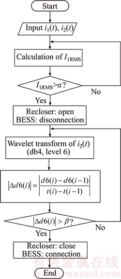
Figure 1 Flowchart of proposed reclosing method

Figure 2 Distribution system model to verify proposed reclosing method
Table 1 Fault conditions


Figure 3 |��d6(i)| in case 1
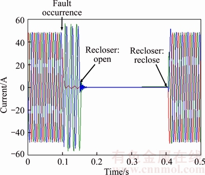
Figure 4 Load 2 current in case 1
4.2.2 Case 2
Figure 5 shows |��d6(i)| in case 2. This value increases rapidly at fault clearing instant. Thus, the fault clearing is detected at 0.404 s, and the reclosing is also performed at this time. The waveform of the current flowing in load 2 is shown in Figure 4. The difference between case 1 and case 2 is a fault resistance. The maximum value of |��d6(i)| when the fault resistance increases is larger in case 2 as shown in the Figures 3 and 5. However, the time to increase above the threshold value of 0.6 is equal to 0.404 s in case 1, so the reclosing time is the same with case 1.
4.2.3 Case 3
Figure 6 shows |��d6(i)| in case 3. The simulation result is very similar with cases 1 and 2.

Figure 5 |��d6(i)| in case 2

Figure 6 |��d6(i)| in case 3
This value is increased rapidly at fault clearing instant and hence the fault clearing is detected at 0.404 s. The waveform of load 2 current is equal to that in Figure 4. The reclosing is performed successfully as shown in Figure 4. The difference between case 1 and case 3 is the fault length. The length from fault point to load in case 3 is longer than that in case 1. In other words, the capacitance in case 3 is larger than case 1. Therefore, |��d6(i)| in case 3 is larger than that in case 1.
4.2.4 Case 4
Figures 7 and 8 show |��d6(i)| and the load 2 current in case 4, respectively. |��d6(i)| is increased rapidly at fault clearing instant and hence the fault clearing is detected at 0.406 s. The difference of reclosing time between above cases and case 4 is only 0.002 s because the trend of rapid increase of |��d6(i)| is very similar. Case 4 has a different fault distance from cases 1 and 3. The fault distance of case 4 is 9 km, and the distance from fault point to load is the closest. Therefore, the capacitance of the distribution line has the smallest value than the other cases. Therefore, |��d6(i)| value is also the smallest in the other cases. Case 4 is an important case, which show that even if the fault occurs only at a short distance of only 1 km from the load, it can be judged that the fault clearing can be detected using the |��d6(i)| proposed in this paper and the reclosing can be performed successful.
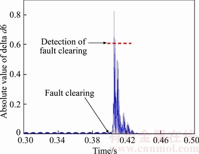
Figure 7 |��d6(i)| in case 4
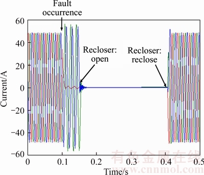
Figure 8 Load 2 current in case 4
4.2.5 Case 5
Figures 9 and 10 show |��d6(i)| and the load 2 current in case 5, respectively. This case is a permanent fault case. Therefore, |��d6(i)| does not increase and hence the reclosing is not attempted.
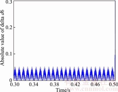
Figure 9 |��d6(i)| in case 5

Figure 10 Load 2 current in case 5
5 Conclusions
Even if the fault has been removed, there is a disadvantage that the outage time becomes longer if it is necessary to wait until the pre-fixed dead time. Also, there is a disadvantage that a large fault current can be repeatedly injected if the fault is not removed and reclosing is performed. Therefore, in this paper, we propose a reclosing method to solve these drawbacks. The proposed method performs the WT of load current. The MW used is db4 with level 6. Then, the absolute value of the slope of detail coefficient is obtained. The calculated value rapidly increases at the fault clearing instant. Therefore, the fault clearing can be judged using this characteristic and then the reclosing is performed. If fault occurs, the BESS is disconnected from the distribution system and it is reconnected after successful reclosing.
To verify the proposed method, the system model was modeled using EMTP. The various simulations according to the fault clearing times, fault resistances, and fault distances are performed. The simulation results show that the fault clearing can be determined using the proposed values and the reclosing can also be successfully performed.
References
[1] HEO J Y, OH Y S, SEO H C, KIM C H. An adaptive autoreclosure scheme with reference to transient stability for transmission lines [J]. Journal of Electrical Engineering& Technology, 2015, 10(3): 795�C803.
[2] RADOJEVI Z M, SHIN JOONG-RIN. New digital algorithm for adaptive reclosing based on the calculation of the faulted phase voltage total harmonic distortion factor [J]. IEEE Trans. Power Delivery, 2007, 22: 37�C41.
[3] GOLSHAN M E, GOLBON N. Detecting secondary arc extinction time by analyzing low frequency components of faulted phase voltage or sound phase current waveforms [J]. Electrical Engineering, 2006, 88: 141�C148.
[4] TERZIJA V V, RADOJEVI Z M. Numerical algorithm for adaptive autoreclosure and protection of medium- voltage overhead lines [J]. IEEE Transactions on Power Delivery, 2004, 19(2): 554�C559.
[5] AHN SANG-PIL, KIM CHUL-HWAN, RAJ K. AGGARWAL, ALLAN T. JOHNS. An alternative approach to adaptive single pole auto-reclosing in high voltage transmission systems based on variable dead time control [J]. IEEE Trans On Power Delivery, 2001, 16(4): 676�C686.
[6] MOHAMMAD ASHRAF HOSSAIN SADI, MOHD HASAN ALI. Combined operation of SVC and optimal reclosing of circuit breakers for power system transient stability enhancement [J]. Electric Power Systems Research, 2014; 106: 241�C248.
[7] LUO Xun-hua, HUANG Chun, JIANG Ya-qun. Improved digital algorithm for adaptive reclosing for transmission lines with shunt reactors [J]. IET Generation, Transmission & Distribution, 2016, 10(9): 2066�C2070.
[8] WANG Xin-pu, YANG Jun, LIU Pei, LIU Wen-qing, YAN Jun, TANG Yu-fei, HE Hai-bo. Online calculation for the optimal reclosing time of transmission lines [J]. Electric Power Components and Systems, 2016, 44(17): 1904�C1916.
[9] VOGELSANG J, ROMEIS C, JAEGER J. Real-time adaption of dead time for single-phase autoreclosing [J]. IEEE Transactions on Power Delivery, 2016, 31(4): 1882�C1890.
[10] OH Jung-Hwan, KIM Jae-Chul. Feature extraction of fault currents associated with multi-shot reclosing scheme in power distribution system [J]. International Journal of Electrical Power & Energy Systems, 2002, 24(1): 79�C85.
[11] PARK Jun-Hee, SEO Hun-Chul, KIM Chul-Hwan, RHEE Sang-Bong. Development of adaptive reclosing scheme using wavelet transform of neutral line current in distribution system [J]. Electric Power Components and Systems, 2016, 44(4): 426�C433.
[12] LEE Jae-Won, KIM Won-Ki, OH Yun-Sik, SEO Hun-Chul, JANG Won-Hyeok, KIM Yoon Sang, PARK Chul-Won, KIM Chul-Hwan. Algorithm for fault detection and classification using wavelet singular value decomposition for wide-area protection [J]. Journal of Electrical Engineering & Technology, 2015, 10(3): 729�C739.
[13] JIANG F, BO Z Q, YANG Q X. The wavelet transform applied to distinguish between transient and permanent fault [C]// Int Conf Power Syst Technol. Beijing, China. 1998: 1116�C1120.
[14] KIM C H, AGGARWAL R K. Wavelet transform in power system.PartI.General introduction to the wavelet transform [J]. IEEE Power Eng J, 2000, 14(2): 81�C87
[15] VETTERLI M, HERLEY C. Wavelets and filter banks: Theory and design [J]. IEEE Trans Signal Process, 1992, 40(9): 2207�C2232.
(Edited by HE Yun-bin)
���ĵ���
����С���任��BESS�����ϵͳ�غ�բ�·���
ժҪ����������˲���С���任��WT���ĵ�ش��ܣ�BESS�������ϵͳ�غ�բ�������÷����Ը��ص�������С���任��Ȼ�����ϸ��ϵ��б�ʵľ���ֵ��ʹ�õ�ĸС����6����db4������ֵ���ٵ����Ӽ���������������������������ִ���غ�բ��Ϊ����֤������ķ����Ƿ���ʣ�ʹ��EMTP�����ڵ���ϵͳ�����̬�����ķ������������ݹ������ʱ�䡢�����迹���Ϸ�Χ���и��ַ��档�����������������������ϸ��ϵ��б�ʾ���ֵ���Լ����������������Ӷ����Գɹ�ʵ���غ�բ��
�ؼ��ʣ������ϵͳ�������̬�����غ�բ����ش���ϵͳ��С���任
Received date: 2016-12-21; Accepted date: 2017-12-05
Corresponding author: RHEE Sang-Bong, PhD, Assistant Professor; Tel: 82�C53�C810�C3097; E-mail: rrsd@yu.ac.kr; ORCID: 0000-0001- 5465-3945

