半连续铸造法制备AA4045/AA3003铝合金包覆铸锭的界面组织和性能
来源期刊:中国有色金属学报(英文版)2016年第3期
论文作者:韩星 邵博 左克生 蒋琳 张海涛 何立子 秦克 崔建忠
文章页码:658 - 664
关键词:铝合金;包覆铸锭;结合界面;扩散;界面强度
Key words:aluminum alloy; cladding billet; bonding interface; diffusion; interfacial strength
摘 要:采用直接水冷半连续铸造法制备AA4045/AA3003铝合金包覆铸锭,对合金界面组织、温度分布、成分分布及力学性能进行研究。结果表明,包覆铸锭界面清晰平直,无气孔、夹杂等缺陷,界面处合金元素在 596~632 °C范围内发生扩散,形成平均厚度的10 μm的扩散层。从AA4045铝合金一侧向AA3003铝合金一侧,Si元素含量下降,Mn元素含量上升。包覆铸锭试样的抗拉强度为103.7 MPa,断口位于AA3003合金侧,界面抗剪切强度为91.1 MPa,说明两种合金通过合金元素的互扩散实现了冶金结合。
Abstract: AA4045/AA3003 cladding billet was prepared by direct chill semi-continuous casting process. The macrostructures, microstructures, temperature distribution, compositions distribution and the mechanical properties at the bonding interface were investigated in detail. The results show that the cladding billet with few defects could be obtained by semi-continuous casting process. At the interface, diffusion layer of about 10 μm on average formed between the two alloys due to the diffusion of alloy elements in the temperature range from 596 to 632 °C. From the side of AA4045 to the side of AA3003, the Si content has a trend to decrease, while the Mn content has a trend to increase gradually. Tensile strength of the cladding billet reaches 103.7 MPa, the fractured position is located on the AA3003 side, and the shearing strength is 91.1 MPa, revealing that the two alloys were combined metallurgically by mutual diffusion of alloy elements.
Trans. Nonferrous Met. Soc. China 26(2016) 658-664
Xing HAN1, Bo SHAO1, Ke-sheng ZUO1, Lin JIANG2, Hai-tao ZHANG1, Li-zi HE1, Ke QIN1, Jian-zhong CUI1
1. Key Laboratory of Electromagnetic Processing of Materials, Ministry of Education, Northeastern University, Shenyang 110819, China;
2. Angang Medium-thickness Plate Mill, Anshan 114021, China
Received 20 April 2015; accepted 28 July 2015
Abstract: AA4045/AA3003 cladding billet was prepared by direct chill semi-continuous casting process. The macrostructures, microstructures, temperature distribution, compositions distribution and the mechanical properties at the bonding interface were investigated in detail. The results show that the cladding billet with few defects could be obtained by semi-continuous casting process. At the interface, diffusion layer of about 10 μm on average formed between the two alloys due to the diffusion of alloy elements in the temperature range from 596 to 632 °C. From the side of AA4045 to the side of AA3003, the Si content has a trend to decrease, while the Mn content has a trend to increase gradually. Tensile strength of the cladding billet reaches 103.7 MPa, the fractured position is located on the AA3003 side, and the shearing strength is 91.1 MPa, revealing that the two alloys were combined metallurgically by mutual diffusion of alloy elements.
Key words: aluminum alloy; cladding billet; bonding interface; diffusion; interfacial strength
1 Introduction
With the intensifying of energy crisis and the development of science technology, cladding materials have excellently physical, chemical and mechanical performance that conventional monolithic alloys do not have [1,2]. The cladding materials can be conventionally produced by extrusion [3], explosive welding [4], spray deposition [5] diffusion bonding [6] and casting [7,8]. However, casting to prepare cladding billet is more efficient and economical than other processes [9]. This process could make two different alloys contact directly at a high temperature and realize metallurgical bonding. In recent years, many novel methods have been developed to fabricate composite sheet or clad billet. GUPTA et al [10] and WAGSTAFF et al [8] prepared the clad ingot via Novelis fusion process [11]. MARUKOVICH et al [7] studied the possibility of continuous-casting of bimetallic components in condition of direct connection of metals in a liquid state. LI et al [12] prepared the 2024/3003 gradient materials by semi-continuous casting using double stream pouring technique. JIANG et al [13] prepared the three-layer composite ingot of 4045/3003/4045 aluminum alloys by direct chill semi-continuous casting process. FU et al [14] developed a process to prepare Al-1Mn and Al-10Si alloy circular clad ingots by direct chill casting. However, there are few reports of interfacial temperature field and bonding shear of cladding billets, which are used to prepare condense pipes of automotive engines.
In this work, AA4045/AA3003 cladding billets with sizes of d140 mm/d110 mm were prepared by semi-continuous casting, based on the casting process parameters which were determined through theoretical analysis, numerical simulation, and experiments [15]. Temperature distribution near the interface was measured. In order to investigate bonding interface structure and bonding strength, the cladding billets were detected by metallographic examination, SEM, microhardness, tensile and shear tests.
2 Experimental
In this work, AA4045 alloy, with high strength and weldability, was selected as the cladding-layer, while AA3003 alloy, with excellent corrosion resistance and low strength was selected as the core-layer. The condense pipes of automotive engines could be produced by perforation extrusion of AA4045/AA3003 cladding billets. The chemical compositions of the two alloys are listed in Table 1.
The apparatus of continuous casting bimetal cladding billets is schematically shown in Fig. 1. It mainly includes outer-crystallizer and inner-crystallizer, which has their own pouring system and cooling system, and starting head. During the casting process, AA3003 was fed into the inner-crystallizer firstly. A supporting layer would be formed near the inner-graphite in several seconds. When the strength of the supporting layer was sufficient to prop up the internal melt, AA4045 was poured into the outer-crystallizer rapidly so that AA4045 could flow into the narrow annular region and the starting head was drawn at the same time. The cladding billet with sizes of d140 mm/d110 mm was prepared successfully. Similarly, several cladding billets were obtained successfully. The casting process parameters are listed in Table 2.

Fig. 1 Schematic diagrams of cladding casting equipment
Table 1 Alloy compositions used in present work (mass fraction, %)

Table 2 Casting process parameters during cladding casting
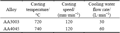

Fig. 2 Schematic diagram of thermocouple positions (top view; unit: mm)
To study the temperature field around the bonding interface during the cladding casting process, four thermocouples were placed at the positions of center (P1), 1/2R(P2), 3/4R(P3) and R(P4) near the bonding interface in AA3003 melt, as schematically shown in Fig. 2. The thermocouples were vertically fixed to the stainless steel rods installed in the starting head and moved down with the lowering of the starting head. These thermocouples were linked to a data logger to record the temperatures every 0.2 s. When the casting was finished, the corresponding temperature data were transferred to a personal computer and then processed to yield a distance-temperature plot.
In order to investigate the microstructure and properties of the cladding billets, the cross section of cladding billet, after being lathed, was corroded to observe macrostructure by an ambient solution of 10% NaOH (mass fraction) for 10 min, while the sample for microstructure was etched by a solution of 5% HF (volume fraction) for 15 s. The metalloscope (Leica-500) and scanning electron microscope ((Zeiss Ultra Plus 60) were used to investigate the mechanism of interfacial bonding. The Vicker hardness (452SVD automatic turret) was measured with a test load of 3 N and a dwell time of 15 s. The specimens for tensile and shear measurement were taken from three different positions respectively. The dimensional drawings of tensile and shear specimens, which were cut by electric discharge machine from different positions of the cladding billet, are shown in Fig. 3. The bonding strength tests, including tensile test and shearing test, were performed using an MTS-810 universal testing machine at a strain rate of 1 mm/min. As shear strength cannot be tested according to the conventional standard due to the arc-shaped bonding interface, a set of home-made die was designed to determine the shearing strength with reference to the above standards by JING et al [16].

Fig. 3 Schematic diagrams of tensile sample (a) and shear sample (b) (unit: mm)
3 Results and discussion
3.1 Macrostructure and microstructure
Figure 4(a) shows the macrostructure of the cross- section of cladding billets after corrosion. The two alloy layers are revealed by two different contrasts. The macrostructure features of AA4045 and AA3003 were different distinctly, and the interface was clearly distinguishable. After AA3003 was poured into the inner-crystallizer, some equiaxed grains formed on the substrates of heterogeneous nucleation at the internal of core-layer. Then, AA3003 continued to solidify along the direction of heat transfer, forming the coarse columnar zone. At the center of core-layer, the isotropic heat transfer resulted in the formation of equiaxed grains. AA4045 melt flowed into the outer-crystallizer through the launder, contacting with the outer-graphite and the supporting layer, and then was cooled intensively by the former. Therefore, the external of cladding-layer was composed of fine equiaxed grains, whereas the internal consisted of coarse columnar crystals.
The micro-interface is shown in Fig. 4(b). On AA4045 side, α(Al) is close to the interface, and then acicular eutectic silicon crystals (Zone A) and α(Al) (Zone B) appeared alternately. It can be seen that acicular eutectic silicon crystals (Zone A) distribute at the boundaries of the coarse α(Al) grains (Zone B) on AA4045 side; whereas some phases containing manganese (Zone C) are embedded in the α(Al) matrix (Zone D) on AA3003 side. In addition, there are no discontinuities, cracks or porosities at the interface, indicating a good bonding of the two alloys.
3.2 Cooling curves of temperature profile near interface during cladding casting process
Figure 5 shows the cooling curves recorded by thermocouples with the lowering of the starting head. As a reference, the solidus (645 °C) of AA3003 and the liquidus (596 °C) of AA4045 are denoted as horizontal auxiliary lines, respectively. According to the temperature fluctuation of the interface (P4) and the auxiliary lines, the cooling process of cladding billet could be divided into three phases, Phase 1 (660-632 °C), Phase 2 (632-596 °C) and Phase 3 (596 °C-room temperature). In Phase 1, AA3003 melt was cooled by the inner-graphite and the interface temperature (P4) decreased below solidus until it contacted with AA4045 melt, whereas other temperature measurement points remained about 670 °C. In Phase 2, the interface temperature rebounded slightly and others still kept nearly unchanged. The rebounding of the interface temperature should be attributed to the feeding and the latent heat of AA4045 melt. At the end of Phase 2, the temperatures of points P4 and P3 began to drop evidently, due to the indirect influence of the secondary cooling water. In Phase 3, all temperatures of the four points have a sharp decrease, especially after the water impact point on the billet surface. Meanwhile, the billet, including the interface region, accomplished the process of solidification.

Fig. 4 Macrostructure (a) and microstructure (b) of cross-section of cladding billet

Fig. 5 Cooling curves near interface during cladding casting process
3.3 Diffusion across bonding interface
The analysis of cooling curves above revealed that AA4045 melt contacted with the supporting layer of AA3003 at a higher temperature (higher than 630 °C) and there were a rebound and temperature remaining near the interface during Phase 2. They should accelerate the diffusion of elements Si and Mn across the interface. In order to investigate the diffusion of elements near the interface, the SEM image of the bonding interface and the corresponding concentration maps of elements Al, Si and Mn are presented in Fig. 6. The results revealed that majority of Si element distributed on AA4045 side, and little Si element could be found on AA3003 side. On the contrary, most of Mn element appeared on AA3003 side, and little diffused to AA4045 side. The bonding interface is distinct and straight.
To quantitatively investigate the alloy element diffusion across the interface, linear analysis of alloy elements around the bonding interface was performed by the energy-dispersive spectroscopy (EDS), as shown in Fig. 7. A marked drop in composition of element Si and a rise in composition of element Mn were observed clearly by each EDS line across the interface region from AA4045 side to AA3003 side. During the cladding casting process, superheat of AA4045 reheated the surface of AA3003 supporting layer to the approximate solid temperature of AA3003 (645 °C) and kept that for more than 10 s. During this period, elements Si and Mn mutually diffused across the interface and a diffusion layer with a thickness of about 10 μm formed. Moreover, the diffusion distance of element Si is longer than that of element Mn, as shown in Fig. 7.
According the Fick’s laws of diffusion, if the diffusion process of every element is independent, the diffusion equation can be shown as
 (1)
(1)
where C is the concentration of elements; t is the diffusion time and x is the distance.

Fig. 6 SEM image (a) of bonding interface along corresponding concentration maps of elements Al (b), Si (c) and Mn (d)

Fig. 7 EDS line scans across bonding interface
The diffusion coefficient (D) can be analyzed by following equation
 (2)
(2)
where D0 is the diffusion constant, Q is the activation energy for diffusion, R is the mole gas constant and T is the thermodynamic temperature.
From Eq. (2), temperature is the most important factor to affect diffusion coefficient. With temperature increasing, diffusion coefficient enlarges sharply. The diffusion of elements mainly occurred during Phase 2 in Fig. 5. From Ref. [17], D0 values of elements Si and Mn in Al are 3.5×10⁻⁵ m2/s (344-632 °C) and 2.2×10⁻⁵ m2/s, (450-650 °C) respectively, while Q values of elements Si and Mn are 123 and 120 kJ/mol, respectively. According to Eq. (2), the diffusion coefficients of element Si in Al are 1.41×10⁻¹² m2/s (569 °C) and 2.78×10⁻¹² m2/s (632 °C), which are slightly larger than those of element Mn in Al, 1.35×10⁻¹² m2/s (569 °C) and 2.61×10⁻¹² m2/s (632 °C). Moreover, the concentration gradient of Si atoms is much larger than that of Mn atoms between AA4045 and AA3003, which further improves the diffusion of Si.

Fig. 8 Vickers hardness near bonding interface
3.4 Mechanical properties of bonding interface
The Vickers microhardness with distance from the bonding interface of AA4045/AA3003 cladding billet was measured, as presented in Fig. 8. It is seen that the microhardness of AA4045 is in the range of HV 78-80, while that of AA3003 is in the range of HV 43-46. The microhardness of bonding interface region is lower than that of AA4045, but higher than that of AA3003. In addition, the microhardness curve shows considerable drop as approaching to the bonding interface. The variation of microhardness is attributed to the decrease of Si contents from AA4045 side to AA3003 side (as shown in Fig. 8).
The interface bonding strength is a directly efficient approach to judge the bonding quality of two alloys. The tensile fracture specimen, which is similar to other tensile fracture specimens, is shown in Fig. 9(a). For all these samples, the failures occurred in AA3003 with lower strength, while the bonding interface remained good. The tensile strengths of different regions of the cladding billet are shown Fig. 9(b), and the average tensile strength of different regions of the cladding billet is 103.7 MPa, indicating that the tensile strength of the bonding interface is greater than that of the softer alloy, AA3003. The discussion of the former part indicates that the interdiffusion of elements Si and Mn is evident around the tensile test. It is the existence of the two elements among the diffusion layer that makes the bonding interface strength exceed the strength of AA3003 due to the effect of solid solution strengthening, but below that of AA4045. LLODY et al [18] reported that the failure of AA3003/AA6111 cladding materials during tensile process always takes place in the softer AA3003 component (Al-1Mn-0.5Fe-0.2Si) because plasticity should predominantly occur in the softer alloy, and failure occurs when the UTS of AA3003 is reached.

Fig. 9 Tensile fractured specimen (a) and tensile strengths of different regions of cladding billet (b)
Therefore, if the two alloys are bonded metallurgically without any defects or discontinuities at the bonding interface, the tensile strength fracture would be located in the softer alloy.
The tensile test just confirmed qualitatively that the strength of bonding interface was higher than that of AA3003. In order to quantitatively detect the bonding strength of the bonding interface, shearing test was conducted. Shear strength plays a significant role in judging the bonding of the cladding billet. Figure 10 shows the variation of shear strength and displacement during shearing process. With the increase of displacement, shear strength reaches the peak gradually and declines sharply, according with the shear fracture process. The shear strengths are nearly uniform, and the mean value of the bonding interface is 91.1 MPa, which is higher than the shear strength of AA3003 (84 MPa).

Fig. 10 Curves of shear strength-displacement during shearing process
To have a profound understanding of the shearing fracture, the interfacial morphology of the sheared surface was examined using scanning electron microscopy. It can be seen that lots of bonding dimples emerge on the shearing surface of the AA3003 side, while a relatively small on the other, as shown in Fig. 11. When a specimen is sheared, the shearing fracture generates bonding dimples, which are similar to those of ductile fracture. As stated by DAS and TARAFDER [19], the weeny and dense dimples indicate the excellent ductility and strength of the material. The EDS analysis, marked in Figs. 11(a) and (b), are shown in Table 3. It can be seen that some Mn-rich phases exist on the AA4045 side, such as P2 and P3, while some Si-rich phases (P5 and P6) distribute on the AA4045 side. The shearing fractures contain the element of the opposite side. It can be revealed that the two alloys adhere each other through the diffusion of alloy elements.

Fig. 11 SEM images showing shearing fracture of bonding interface
Table 3 EDS analysis of shearing fracture (mass fraction, %)

During the cladding casting process, when the overheated molten AA4045 contacts with the supporting layer of AA3003, the former would reheat the supporting layer of the later and remain it in the range of 596-632 °C for several seconds, as presented in Fig. 5. Meanwhile, elements Si and Mn diffuse to the opposite side with higher diffusion coefficient and AA4045 melt near the interface start to solidify in the way of heterogeneous nucleation. Based on reheating of the supporting layer and atomic diffusion near the bonding interface, excellent metallurgical bonding is obtained between the cladding-layer and the core-layer.
4 Conclusions
1) The AA4045/AA3003 cladding billet in sizes of d140 mm/d110 mm was fabricated by direct chill semi-continuous casting process.
2) The two different aluminum alloys were combined by excellent metallurgical bonding with few defects. Elements Si and Mn diffused across the interface and a diffusion layer with a thickness of 10 μm formed.
3) The average tensile strength and shear strength of the cladding billet are 103.7 MPa and 91.1 MPa, respectively. The tensile failure occurred on AA3003 side, indicating that the interface bonding strength is higher than the strength of softer alloy. The shearing fractures contained the element of the opposite side, revealing that the two alloys were combined metallurgically by mutual diffusion of alloy elements.
References
[1] MILLER W S, ZHUANG L, BOTTEMA J, WITTEBROOD A J, SMET P D, HASZLER A, VIEREGGE A. Recent development in aluminium alloys for the automotive industry [J]. Materials Science and Engineering A, 2000, 280: 37-49.
[2] WANG Qian, LENG Xue-song, YANG Tian-hao, YAN Jiu-chun. Effects of Fe-Al intermetallic compounds on interfacial bonding of clad materials [J]. Transactions of Nonferrous Metals Society of China, 2014, 24(1): 279-284.
[3] HAGHIGHAT H, SHAYESTEH H. Upper bound analysis for hybrid sheet metals extrusion process through curved dies [J]. Transactions of Nonferrous Metals Society of China, 2014, 24(12): 3285-3292.
[4] MAMALIS A G, SZALAY A, VAXEVANIDIS N M, MANOLAKOS D E. Fabrication of bimetallic rods by explosive cladding and warm extrusion [J]. Journal of Materials Processing Technology, 1998, 83: 48-53.
[5] SINGER A R E. The principles of spray rolling of metals [J]. Metals and Materials, 1970, 4: 246-250, 257.
[6] YUAN Xin-jian, SHENG Guang-min, LUO Jun, LI Jia. Microstructural characteristics of joint region during diffusion-brazing of magnesium alloy and stainless steel using pure copper interlayer [J]. Transactions of Nonferrous Metals Society of China, 2013, 23(2): 599-604.
[7] MARUKOVICH E I, BRANOVITSKY A M, NA Y S, LEE J H, CHOI K Y. Study on the possibility of continuous-casting of bimetallic components in condition of direct connection of metals in a liquid state [J]. Materials Design, 2006, 27: 1016-1026.
[8] WAGSTAFF R B, LLOYD D J, BISCHOFF T F. Direct chill casting of clad ingot [J]. Materials Science Forum, 2006, 519-521: 1809-1814.
[9] WANG Tong-min, CAO Fei, ZHOU Peng, KANG Hui-jun, CHEN Zong-ning, FU Yan-an, XIAO Ti-qiao, HUANG Wan-xia, YUAN Qing-xi. Study on diffusion behavior and microstructural evolution of Al/Cu bimetal interface by synchrotron X-ray radiography [J]. Journal of Alloys and Compounds, 2014, 616: 550-555.
[10] GUPTA A, LEE S T, WAGSTAFF R B. Direct chill casting of aluminium-manganese against aluminium-silicon layer vis Novelis fusion process [J]. Materials Technology, 2007, 22: 71-75.
[11] BENEDYK J C. Novelis Fusion process: breakthrough in the simultaneous DC casting of multiple aluminum alloy layers for rolling ingot [J]. Light Metal Age, 2006, 64(4): 48-50.
[12] LI Yuan-yuan, ZHANG Wei-wen, FEI Jin, ZHANG Da-tong, CHEN Wei-ping. Heat treatment of 2024/3003 gradient composite diffusion behavior of the alloying elements [J]. Materials Science and Engineering A, 2005, 91: 124-130.
[13] JIANG Hui-xue, ZHANG Hai-tao, QIN Ke, CUI Jian-zhong. Direct-chill semi-continuous casting process of three layer composite ingot of 4045/3004/4045 aluminum alloys [J]. Transactions of Nonferrous Metals Society of China, 2011, 21(8): 1692-1697.
[14] FU Y, JIE J C, WU L, PARK J, SUN J B, KIM J, LI T J. Microstructure and mechanical properties of Al-Mn and Al-10Si alloy circular clad ingot prepared by direct chill casting [J]. Materials Science and Engineering A, 2013, 561: 239-244.
[15] HAN Xing, SHAO Bo, ZHANG Hai-tao, CUI Jian-zhong. Numerical simulation on cladding casting of composite ingot [J]. Journal of Natural Science: Northeastern University, 2014, 35(7): 969-973. (in Chinese)
[16] JING Yu-an, QIN Yi, ZANG Xiao-ming, LI Ying-hong. The bonding properties and interfacial morphologies of clad plate prepared by multiple passes hot rolling in a protective atmosphere [J]. Journal of Materials Processing Technology, 2014, 214: 1686-1695.
[17] NAGASAKI S. Data book of metals [M]. Tokyo: Japan Institute of Metals, 1993.
[18] LLODY D J, GALLERNEAULT M, WAGSTAFF R B. The deformation of clad aluminum sheet produced by direct chill casting [J]. Metallurgical and Materials Transactions A: Physical Metallurgy and Materials Science A, 2010, 41: 2093-2103.
[19] DAS A, TARAFDER S. Experimental investigation on martensitic transformation and fracture morphologies of austenitic stainless steel [J]. International Journal of Plasticity, 2009, 25: 2222-2247.
韩 星1,邵 博1,左克生1,蒋 琳2,张海涛1,何立子1,秦 克1,崔建忠1
1. 东北大学 材料电磁过程研究教育部重点实验室,沈阳 110819;2. 鞍钢股份中厚板厂,鞍山 114021
摘 要:采用直接水冷半连续铸造法制备AA4045/AA3003铝合金包覆铸锭,对合金界面组织、温度分布、成分分布及力学性能进行研究。结果表明,包覆铸锭界面清晰平直,无气孔、夹杂等缺陷,界面处合金元素在596~632 °C范围内发生扩散,形成平均厚度的10 μm的扩散层。从AA4045铝合金一侧向AA3003铝合金一侧,Si元素含量下降,Mn元素含量上升。包覆铸锭试样的抗拉强度为103.7 MPa,断口位于AA3003合金侧,界面抗剪切强度为91.1 MPa,说明两种合金通过合金元素的互扩散实现了冶金结合。
关键词:铝合金;包覆铸锭;结合界面;扩散;界面强度
(Edited by Wei-ping CHEN)
Foundation item: Project (2012CB723307) supported by the National Basic Research Program of China; Project (51204046) supported by the National Natural Science Foundation of China; Project (20130042130001) supported by the Doctoral Fund of Ministry of Education of China
Corresponding author: Hai-tao ZHANG; Tel: +86-24-83681431; Fax: +86-24-83681758; E-mail: haitao_zhang@epm.neu.edu.cn
DOI: 10.1016/S1003-6326(16)64155-9

