J. Cent. South Univ. Technol. (2008) 15: 404-410
DOI: 10.1007/s11771-008-0076-x

Force analysis of pile foundation in rock slope based on upper-bound theorem of limit
ZHAO Ming-hua(赵明华)1, LIU Jian-hua(刘建华)1, 2, LIU Dai-quan(刘代全)3, WANG You(汪 优)1
(1. Geotechnical Institute, Hunan University, Changsha 410082, China;
2. School of Highway Engineering, Changsha University of Science and Technology, Changsha 410076, China;
3. Hunan Expressway Administration Bureau, Changsha 410001, China)
Abstract: Based on the characteristic that the potential sliding surfaces of rock slope are commonly in the shape of either line or fold line, analysis thought of conventional pile foundation in the flat ground under complex load condition was applied and the upper-bound theorem of limit analysis was used to compute thrust of rock layers with all possible distribution shapes. The interaction of slope and pile was considered design load in terms of slope thrust, and the finite difference method was derived to calculate inner-force and displacement of bridge pile foundation in rock slope under complex load condition. The result of example shows that the distribution model of slope thrust has certain impact on displacement and inner-force of bridge pile foundation. The maximum displacement growth rate reaches 54% and the maximum moment and shear growth rates reach only 15% and 20%, respectively, but the trends of inner-force and displacement of bridge pile foundation are basically the same as those of the conventional pile foundation in the flat ground. When the piles bear the same level lateral thrust, the distribution shapes of slope thrust have different influence on inner-force of pile foundation, especially the rectangle distribution, and the triangle thrust has the smallest displacement and inner-force of pile foundation.
Key words: pile foundation; rock slope; inner-force calculation; finite difference method; upper-bound theorem of limit analysis
1 Introduction
With high speed development of the highway construction in western mountainous region of China and increasing of viaduct construction to overstep rivers and valleys, many pile foundations of bridges have to be built in abrupt side slopes in order to meet the requirement of environment protection and geometric consideration[1-2]. There is no systematic and in-depth research on pile foundation of bridge in slopes for bearing mechanism, and conventional calculation methods can hardly meet the challenge of the complicated condition, including geology, topography, loading and working condition[3]. In addition, no appropriate benchmark or criterion so far can direct the corresponding design calculation or safety monitoring control[4-5].
Inner-force calculation of pile foundation of bridge in rock slope is far more complicated than that of anti-slide piles or pile with inclination load of pile head. The existence of crack, joint,interlayer and fault can form certain potential sliding surface, which may generate lateral thrust on the pile foundation[6-7]. Accordingly, this type of pile foundation has both bearing and anti-slip functions[8-9], and performs as both “active pile” and “passive pile”, subjected to not only the lateral pressure from the rock slope, but also the inclination load from the superstructure. Therefore, it is usually difficult to carry out analytic solution.
Based on a thorough consideration of the abnormity and multiformity of slope thrust, upper-bound theorem of limit analysis was adopted to calculate thrust of the rock slope. According to the calculation method of pile in flat ground and considering all possible distribution manners to conclude the interaction of pile foundation, the flexural differential equation of pile foundation in rock slope was established and solved by simplifying manner of thrust and resistance through finite difference method. Through inner-force and displacement calculation of pile foundation, the force and displacement allocation characteristics of pile foundations in rock slope were analyzed in this work.
2 Thrust of slope
Test results show that slope thrust behaves in triangle distribution fashion if the slope rock is composed of loose material (sand). The triangle distribution model is still applied when slope thrust is close to a parabola distribution with the top point near the sliding surface if the slope body material is clay[10]. Moreover, some in-situ tests data indicate that thrust is distributed in the form of parabola with the peak above the sliding surface and almost zero near the earth’s surface if slope soil’s strength is dependent on internal friction angle such as accumulated and fractured rock layers. Model testing results are consistent with those of in-situ tests. However, parabola distribution thrust is adopted to consider that rock slopes where pile foundation of bridge exists are commonly accumulated and fractured rock layers. The position of the corresponding composite force is commonly relatively fixed for specific distribution model. According to different rock and soil types of slope, DAI[11] summarized the disciplinarian (Table 1) from the results of model tests and in-situ tests.
Table 1 Distribution functions of thrust of slope
Note: h2 is depth of pile in rock or soil, k is shape factor, and E is elastic modulus.
The slope thrust distribution directly influences the inner-force calculation accuracy of pile foundation. But the factors that influence distribution of slope thrust are complex and variable, and different slopes have different distribution models. The inner-force calculation of bridge pile foundation is based on the measured thrust data as far as possible. For situation absent measured data, the choice of slope thrust distribution should fully consider the strength, lithology and occurrence of rock mass.
3 Upper-bound method analysis of slope thrust based on strength reduction
Rock mass is a kind of discontinuous and an symmetrical plastid with plenty of discontinuities like crack, joint, interlayer and fault, and all of these have a great impact on the strength of the rock mass[12-13]. The major influencing factors of slope deformation are attitude, landform, space distribution range, composite relation and shear strength of structural plane[14]. The line and fold line sliding surfaces mostly occur in rock slope, and the method that connects structural plane to determine sliding surfaces can basically reflect objective condition.
3.1 Basic assumption
To use upper-bound theorem for analysis, the theoretical equations in the derivation process are based on the following assumptions[15].
1) Slope rock mass is rigid body.
2) In offset procedure, weak interbeds are defined as potential sliding surfaces. Energy dissipation only occurs in slice surface and lateral surface, and it does not take place in slice interior.
3) The adjacent slices accord with displacement coordination principles, namely there is no overlap or deviation between slices.
4) The material observes Mohr-Coulomb failure criterion and the associated flow law.
3.2 Upper-bound theorem of limit analysis
First of all, the strength of rock mass around pile foundation is reduced as follows:
 (1)
(1)
where c is the cohesion strength; φ is the internal friction angle; c and φ are shear resistance indexes of rock mass around pile; cm and φm are actual shear resistance indexes for rock mass to keep equilibrium; F is the shear resistant strength reduction factor or strength safety factor.
Dividing the rock mass above the potential sliding surface into n slices from the top to the bottom, the ith slice bears the gravity of all slices Wi, and the lateral horizontal pressure Qi. The velocity of the ith slice is set as vi, and the relative velocity between the ith and (i+1)th slice is set as  According to the assumption (4), the angle between vi and potential sliding surface is φei, and that between
  and the interface of these two slices is
  The external load is viewed as Qp that acts on the 1st slice[16-17]. When the slope is up to its limit state, external force power is
 (2)
(2)
where αi is the angle between vi and interface.
Interior energy consumption occurs at the bottom of the wedge block and interface between the wedge blocks. But there is no energy dissipation inside the rigid body. There are normal stress σi(effective stress), vertical to the surface, additional stress ui and shear stress τfi.
Thus, the interior energy dissipation at the ith slide is
 (3)
(3)
where li is the length of pile segments in slide.
According to Mohr-Coulomb failure criterion, the ultimate shear strength is
 (4)
(4)
where cei is the effective cohesion strength.
Substituting Eqn.(4) into Eqn.(3), the interior energy dissipation at ith slide interface is
 (5)
(5)
The total interior energy dissipation is

 (6)
(6)
According to the principle of virtual work we can get
D=Ds (7)
The adjacent slices accord with displacement coordination principles, that is to say, the velocity polygon should be closed
 (8)
(8)
where θ1 is the angle between v1 and v2,  is the angle between v1 and
  θ2 is the angle between v2 and
Following the known velocity of the 1st slice, velocity vi of arbitrary slice is linear function of the 1st slice velocity v1:
 (9)
(9)
where
 (10)
(10)
 (11)
(11)
Substituting Eqns.(2), (6) and (9) into Eqn.(7), we get
 (12)
(12)
where QP is the lateral thrust of rock layers and
 ,
,

4 Inner-force analysis of pile
4.1 Basic assumption and differential equation
According to the experimentation and analytical results, the parabola distribution can be used to describe thrust function of rock layers in slope, and the assumptions can be established for pile foundation in steep slope under inclined and eccentric load[18].
1) The pile is under elastic condition.
2) The inclined and eccentric load acts on pile top, Q0 is the horizontal component of forces,P0 is the vertical component of forces, and M0 is eccentric moment.
3) Above the potential sliding surface, the pile bears parabolic thrust whose distribution function Qz is consistent with the following model:
 (0≤z≤h1) (13)
where h1 is the length of the pile above the potential sliding surface. When ζ=0, η=0 and p0≠0, the distribution function is a rectangle distribution pattern; when ζ=0, p0=0 and η≠0, it is a triangle distribution pattern; when ζ=0, η≠0 and p0≠0, the function is a trapezium distribution pattern; when p0=0, ζ≠0 and η≠0, the parabola function is adopted.
4) Pile bears lateral earth resistance with the function of q(x, z)=mzn, where z is the distance from section to earth surface, m is the coefficient of subsoil reaction.
5) The axial force of pile changes with the linear depth variety due to lateral friction resistance and pile gravity, and its distribution is as follows:
P(z)=P0+fz (14)
where P(z) is z axial force of pile below the top of pile segment,P0 is the axial force of pile top(earth surface), f is the axial force including its gravity and lateral friction resistance along axial pile shaft, f=Aγc-Uqs/2, A is the section area, γc is the unit gravity of pile, U is the section perimeter, qs is the unit friction resistance.
4.2 Derivation of differential equation
Extracting one segment from pile shaft and calculating moments at the down midpoint of segment bottom, the balance equation of moment can be derived as[19]
 (15)
(15)
Simplifying Eqn.(15) as
 (16)
(16)
where 

 E is elastic modulus; Ip is the inertia moment.
In terms of its bearing situation, bridge pile foundation in rock slope is divided into two different segments, i.e. the segment bearing thrust and segment embedding bedrock (Fig.1). Their differential equations are as follows.
1) For segment bearing thrust, there exists
 (17)
(17)
2) For segment embedding bedrock, there exists
 (18)
(18)
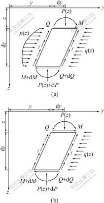
Fig.1 Stress analysis diagrams of pile segments: (a) Segment bearing thrust; (b) Segment embedding bedrock
Differential equation and boundary condition of bridge pile foundation in rock slope can be obtained as follows by adopting the difference schemes.
1) For segment bearing thrust, we have


 (19)
(19)
where ?Ω is the function correlated with shape of thrust.
2) For segment embedding bedrock, there exists

 (20)
(20)
The boundary conditions of pile top and pile tip are respectively as follows:
1) For pile top freedom, we have
 (21)
(21)
2) For pile bottom fixed, we have
 (22)
(22)
The pile shaft should satisfy continuous conditions of displacement, deflection, shearing force and moment in interface.
 (23)
(23)
where K is segment number of interface.
According to the displacement of pile segments, the resistance, moment and shearing force of pile shaft can be obtained as follows
![]()
Additional explanation of the difference format is given as follows.
1) Pile segments are separated based on different bearing forces of the pile shaft, and Eqn.(21) is adopted according to their bearing behavior.
2) Pile segments are separated because of different rock layers, and “M” method or “K” method was adopted based on actual condition of bearing load segment and fixed segment in difference equation.
3) Pile segments are separated because of the difference in rigidity and sectional shape of pile foundation, and λ, k and EIp will be properly adjusted in all equations above.
5 Analysis of example
One pile foundation is built in rock slope, and the natural angle is 60?. The height difference between mountaintop and valley is 210 m, and the pile is 30 m in length, density of concrete??γ=25 kN/m3, and unit area friction resistance τ=40 kN/m2. The pile length above potential sliding surface l1=10 m, and the parameters of rock are shown in Table 2. The coefficient of subgrade reaction m1=5 MN/m4 and the pile length embedding bedrock l2=20 m. The pile diameter is 2 m, and elastic modulus of concrete Ep=18 GPa. Based on upper-bound theorem of limit analysis, the loads on the pile top are as follows: axial force 9.1 MN, horizontal force 170 kN, eccentric moment 1 MN・m, and slope thrust 500 kN. The displacement, moment and shear diagrams of pile shaft calculated by finite difference method are shown in Figs.2-6.
Table 2 Physical mechanics parameters of rock layers
Different distribution shapes of thrust will have different influences on pile foundation, but the trends of the inner-force are almost the same. Table 3 presents comparative results of displacement, moment and shear with different distribution shapes of thrust.
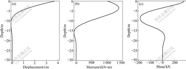
Fig.2 Displacement (a), moment (b) and shear (c) of pile shaft without thrust
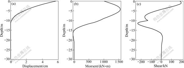
Fig.3 Displacement (a), moment (b) and shear (c) of pile shaft with rectangle distribution thrust
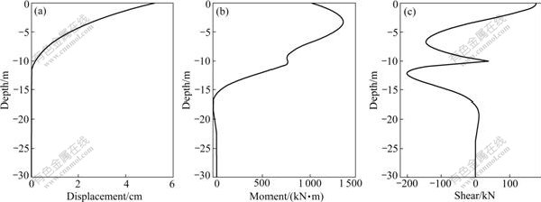
Fig.4 Displacement (a), moment (b) and shear (c) of pile shaft with triangle distribution thrust
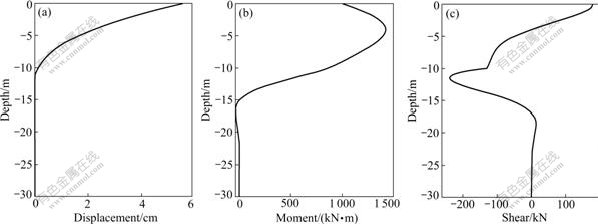
Fig.5 Displacement (a), moment (b) and shear (c) of pile shaft with parabola distribution thrust
Fig.6 Displacement (a), moment (b) and shear (c) of pile shaft with trapezium distribution thrust
Table 3 Displacement, moment and shear of pile shaft with different distribution shapes of thrust
Referring once again to Figs.2-6 and Table 2, it can be seen that the displacement, moment and shear of pile shaft increase distinctly because of slope thrust compared with those of pile foundation without action of lateral loads. The displacement of pile top is from 3.75 cm to 5.79 cm, the maximum rate of growth attains 54%, and the result shows that the lateral thrust of slope has a great impact on deformation of pile. The moment of pile shaft is from 1 355.90 to 1 552.90 kN・m, and the maximum growth rate reaches only 15%. The shear force of pile shaft is from -198.95 to -239.49 kN, and the maximum growth rate is about 20%. Therefore, we can draw the conclusion that the distribution shapes of thrust have major impact on the displacement, but a minor effect on the inner-force.
6 Conclusions
1) The potential sliding surface is determined in discontinuous plane of rock slope interior, the upper- bound theorem of limit analysis is adopted to calculate thrust in rock slope. The finite difference equation of pile foundation in rock slope is established by considering interaction between pile and slope.
2) It is feasible to use the finite difference method to calculate the displacement, moment and shear of bridge pile foundation in rock slope under complex load condition. The distribution shapes of thrust have certain influence on deformation and stress, and trends of displacement and inner-force are almost the same as those of conventional pile without lateral thrust.
3) With the same slope thrust, different distribution shapes of thrust have different influence on inner-force of pile foundation. On the whole, the rectangle distribution thrust has the greatest influence on inner-force and deformation of pile foundation because the localization of lateral thrust is high. However, the triangle distribution thrust has the least influence on the inner-force and deformation of pile foundation because the location of lateral force is low. Therefore, it is dangerous to adopt triangle distribution to calculate in design.
References
[1] ZHAO Ming-hua, ZHANG Ling, YANG Ming-hui. Settlement calculation for long-short composite piled raft foundation [J]. Journal of Central South University of Technology, 2006, 13(6): 749-754.
[2] MCCULLOUGH N J, DICKENSON S E. The behavior of piles in sloping rock fill at marginal wharves [J]. Journal of Geotechnical and Geoenvironmental Engineering, 2004, 16(1): 1-10.
[3] DYKEMAN P, VALSANGKAR A J. Model studies of socketed caissons in soft rock[J]. Can Geotech J, 1996, 33(2): 747-759.
[4] KIMURA M, ZHANG F. Seimic evaluations of the pile foundation with three different methods based on three-dimensional elasto- plastic finite element [J]. Journal of Japanese Geotechnical Society of Soils and Foundations, 2000, 40(5): 113-132.
[5] SASTRY V V R N, MEYERHOF G G. Behavior of flexible piles in layered sands under eccentric and inclined loads [J]. Can Geotech J, 1994, 31(4): 513-520.
[6] WU Hong-li. Study on calculation method of laterally loaded pile [J]. China Civil Engineering Journal, 1995, 28(2): 20-28. (in Chinese)
[7] DAI Zi-hang, PENG Zhen-bing. Finite difference method based on “m-k” method for calculation of internal forces of a whole stabilizing pile [J]. Rock and Soil Mechanics, 2002, 23(3): 321-324. (in Chinese)
[8] ZHAO Ming-hua, HOU Yun-qiu, CAO Xi-ren. Study on the behavior of inclinedly loading piles [J]. Journal of Hunan University, 1997, 24(2): 98-102. (in Chinese)
[9] HOU Yun-qiu, ZHAO Ming-hua, CAO Xi-ren. Study on bearing capacity of inclined loading piles[J]. Central South Highway Engineering, 1998(1): 39-42. (in Chinese)
[10] XU Liang-de, YIN Dao-cheng, LIU Hui-ming. Resistance distribution before pile when landslide body is clay [M]. Beijing: China Railway Press, 1990: 92-99.(in Chinese)
[11] DAI Zi-hang. Study on distribution laws of landside-thrust and resistance of sliding mass acting on anti-slide piles [J]. Chinese Journal of Rock Mechanics and Engineering, 2002, 21(4): 517-521. (in Chinese)
[12] WAISH J B. Effect of pore pressure and confining pressure on fracture permeability [J]. Int J Rock Mech Min Sci Geomech Abstr, 1991, 28(5): 429-435.
[13] BANDIS S C, LUMSDEN A C, BARTON N R. Fundamentals of rock joint deformation [J]. Int J Rock Mech Min Sci Geomech Abstr, 1983, 20(6): 249-268.
[14] WANG Zai-quan. Stability research of complex slope engineering system [M]. Xuzhou: China University of Mining and Technology Press, 2000. (in Chinese)
[15] CHEN Wei-fa, LIU Xi-la. Limit analysis in soil mechanics [M]. Amsterdam: Elsevier Science, 1990.
[16] YU H S, SALGADO R, SLOAN S W, KIM J M. Limit analysis versus limit equilibrium for slope stability [J]. Journal of Geotechnical and Geoenvironmental Engineering, ASCE, 1998, 124(1): 1-11.
[17] DUNCAN J M. State of the art: Limit equilibrium and finite element analysis of slope [J]. Journal of Geotechnical Engineering, ASCE, 1996, 122(7): 577-595.
[18] CHEN L T, POULOS H G. Piles subjected to lateral soil movements [J]. Journal of Geotechnial and Geoenvironmental Engineering, ASCE, 1997, 123(9): 802-811.
[19] MEZAZIGH S, LEVACHER D. Laterally loaded piles in sand: Slope effect on p-y reaction curves [J]. Can Geotech J, 1998, 35(3): 433-441.
(Edited by CHEN Wei-ping)
Foundation item: Project(50578060) supported by the National Natural Science Foundation of China
Received date: 2007-09-23; Accepted date: 2007-11-08
Corresponding author: ZHAO Ming-hua, Professor; Tel: +86-731-8821590; E-mail: mhzhaohd@21cn.com

