J. Cent. South Univ. Technol. (2011) 18: 568-572
DOI: 10.1007/s11771-011-0732-4
Thermal analysis of an innovative flat heat pipe radiator
KOU Zhi-hai(寇志海)1, BAI Min-li(白敏丽)1, YANG Hong-wu(杨洪武)2
1. School of Energy and Power Engineering, Dalian University of Technology, Dalian 116024, China;
2. Dalian Thermalway Heat Transfer Technology Co. Ltd., Dalian 116110, China
? Central South University Press and Springer-Verlag Berlin Heidelberg 2011
Abstract: An innovative flat heat pipe radiator was put forward, and it has the features of high efficiency of heat dissipation, compact construction, low thermal resistance, light weight, low cost, and anti-dust-deposition. The thermal analysis of the flat heat pipe radiator for cooling high-power light emitting diode (LED) array was conducted. The thermal characteristics of the flat heat pipe radiator under the different heat loads and incline angles were investigated experimentally in natural convection. An electro-thermal conversion method was used to measure the junction temperature of the LED chips. It is found that the integral temperature distribution of the flat heat pipe radiator is reasonable and uniform. The total thermal resistance of the flat heat pipe radiator varies in the range of 0.38-0.45 K/W. The junction temperatures of LED chips with the flat heat pipe radiator and with the aluminum board at the same forward current of 0.35 A are 52.5 and 75.2 ?C, respectively.
Key words: energy technology; thermal analysis; flat heat pipe radiator; thermal characteristics
1 Introduction
Due to their advantages of energy saving, environmental protection, good reliability, quick response and long lifetime, light emitting diodes (LEDs) have become a popular lighting source in daily life. However, with the development of the denseness and the miniaturization of LEDs, the heat flux per unit increases rapidly. When the heat cannot be immediately dissipated to the ambient surroundings, the junction temperature increases rapidly, which will decrease the light efficiency, induce the peak wavelength shift, and significantly reduce the lifetime of LEDs [1]. Therefore, a proper thermal management of LED plays a vital role in achieving the reliability and the optimal performance of LED devices.
As a good packaging technology is the way to solve the heat dissipation problem, it is a challenge to develop this technology in the limited space of LED. The general and cost-saving method is to improve the external heat sink. Piezoelectric fan was utilized to form forced convection of air for cooling LEDs [2-3]. CHAU et al [4] investigated the cooling enhancement design of LED through an electrohydrodynamic (EHD) approach. MA et al [5] designed an innovative liquid-cooling system for cooling LED array. LUO and LIU [6] used a microjet-based cooling system to cool high power LEDs. Their results show that the optimized microjet cooling system can be applied in the thermal management of a 220 W LED lamp. A silicon-based thermoelectric (TE) device on high power LEDs was also investigated [7-8]. The traditional heat pipe was applied to the thermal management of high-power LEDs [9-11]. LU et al [12] developed a novel loop heat pipe cooling device for high-power LED to improve the thermal characteristics of high-power LED. Their results show that the junction temperature of high-power LED can be controlled steadily under 100 °C for the heat load of 100 W.
In the present work, an innovative flat heat pipe radiator is put forward to realize the thermal management for high-power LED array. The thermal analysis and experimental investigation on heat transfer performance of the flat heat pipe radiator for cooling LED array are established.
2 Innovative flat heat pipe radiator
The innovative flat heat pipe radiator is shown in Fig.1. It is composed of three parts: a triangular prism substructure, a vertical flat heat pipe (FHP), and vertically placed fins. The material of the flat heat pipe radiator is aluminum. The inner surface of FHP is covered with the microgrooves to form a capillary wick structure with sufficient capillary forces to circulate the working fluid (acetone) between the condenser and the evaporator of FHP. When the heat is applied to the substructure of the flat heat pipe radiator, it is conducted through the substructure to the evaporator of FHP. The working fluid in the evaporator vaporizes, converts into vapor, and then flows into the condenser through the vapor pore. The vapor releases the heat in the condenser of FHP and becomes liquid, which is driven by capillary forces to return to the evaporator through the micro- grooves. Finally, the heat is dissipated through the base board of the FHP condenser and fins to the surroundings by convection.
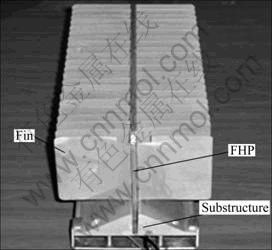
Fig.1 Photo of innovative flat heat pipe radiator
The novel flat heat pipe radiator has many advantages. 1) It uses the temperature uniformity of FHP with a low thermal resistance to extend the fin area with a minimal temperature drop. 2) Because the FHP is vertically placed, the gravitational force provides an extra driving force to circulate the working fluid from the condenser to the evaporator, which will strengthen the capillary limit and decrease the thermal resistance of FHP. 3) The vertical fins can enhance the natural convection between fans and air, and avoid the dust deposition. 4) The material of the flat heat pipe radiator is aluminum, so it has the features of light weight and low cost.
3 Experimental investigation
Fig.2 shows the schematic setup used to carry out the experiment. It consists of a flat heat pipe radiator, an isothermal chamber, an infrared thermal camera (IR camera), a data acquisition system, an integrating sphere, thermocouples, a variable DC power supply and an AC power supply. The dimensions of the substructure are 100 mm × 27 mm × 340 mm, and the dimensions of FHP are 300 mm (length) × 100 mm (width) × 4 mm (height). The 10×4 LED array is welded in the aluminum board which is fixed to the substructure with bolts. Forty-four fins are fixed on the external surface of the condenser of FHP. Here, the fin height is 60 mm, fin thickness is 1 mm and fin spacing is 14 mm. An isothermal chamber is used to guarantee the natural convection of surroundings where the thermal measurement is carried out. During testing, the ambient temperature in the chamber is set at 28.5 °C, and a set of forward currents of 0.35, 0.4, 0.5, and 0.6 A are applied to the LED array by the DC power supply. The temperatures of the flat heat pipe radiator are measured by 14 pairs T-type thermocouples (with deviation of ±0.5 °C): three pairs located at the substructure, two pairs located at the evaporator of FHP, six pairs located at the condenser of FHP, and three pairs located at the tip of the fins, as shown in Fig.2. The temperatures measured by thermocouples and the forward voltage and current of LED array are collected by the Agilent 34970A data acquisition system. When the temperatures reach the steady state, the integral temperature distribution is acquired by the Fluke Ti55FT IR camera to verify the temperature uniformity of the flat heat pipe radiator.
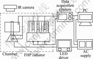
Fig.2 Schematic diagram of experimental setup
4 Thermal analysis
The junction temperature of LED chips is significantly influenced by the ambient temperature and heat sink. In general, the junction temperature of high-power LED should be less than 110 °C [13]. In this work, an electro-thermal conversion method is used to measure the junction temperature of LED chips. The junction temperature rise is linearly related to the change of voltage drop in the following way for LED chips and the slope is known as K factor [14]:
K=dVf /dTj (1)
where K is a constant defining the relationship between changes in the junction temperature and the forward voltage, dVf is the differential of the forward voltage, and dTj is the differential of the junction temperature.
The junction temperature can be expressed as
Tj=Ta + (Vf -Va)/K (2)
where Va represents the transient forward voltage at the ambient temperature Ta when the LED is electrified.
LED is a photoelectrical device. The heat power dissipation via the external heat sink is determined by
Pt=Pd-Popt (3)
where Popt is the output optical power and is measured by the integrating sphere.
The input electrical power Pd can be expressed as
Pd=Vt ?It (4)
where Vt and It are the total forward voltage and current of LED array.
In this work, the thermal resistance is defined by the ratio of the temperature difference ?T to the heat flux Q, which generates this temperature difference:
R =?T/Q (5)
The low thermal resistance is highly appreciated for achieving good thermal and optical performance of LED array. The thermal resistance of the flat heat pipe radiator cooling LED array includes two main parts, as shown in Fig.3. The first part is the packaging thermal resistance of the LED chip, which includes the thermal conduction resistance (Rj-s) between the LED junction and the heat slug and the thermal conduction resistance (Rs-b) between the heat slug and the board. The packaging thermal resistance is related to the LED chip packaging technology. The second part is the thermal resistance of the external heat sink. It contains: 1) the thermal conduction resistance (Rb-e) between the board and the evaporator of the FHP, which is mainly determined by the material and dimension of the substructure, 2) the thermal resistance (Rhp) of FHP between the evaporator and the condenser of the FHP, which is affected by the structure and material of the wick, the physical characteristics and the filling ratio of working liquid, and the processing technique, and 3) the thermal resistance of natural convection (Rcon) between the fins and the environment, which is influenced by the structure, pitch, and height of the fins. In Fig.3, Tj,max is the maximum junction temperature of LED array; Tb,max is the maximum temperature of the substructure; Te is the mean temperature of the evaporator of FHP; Tc is the mean temperature of the condenser of the FHP; Ta is the ambient temperature.
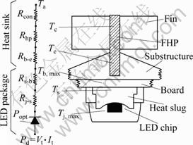
Fig.3 Thermal resistance map of cooling LED array
5 Results and discussion
The start-up process of the flat heat pipe radiator at the forward current of 0.35 A is shown in Fig.4. The total forward voltage of LED array decreases gradually with increasing the time. The PN junction has the negative temperature characteristic at a constant forward current. When the LED array is electrified, the junction temperature of LED chips increases, which decreases the forward voltage. The temperatures of the flat heat pipe radiator begin to become steady at about 30 min. The flat heat pipe radiator has a certain thermal capacity and the heat transfer coefficient of the natural convection between the fins and the surroundings is quite low. Decreasing the thermal capacity or increasing the heat transfer coefficient can shorten the required start-up time. It is also noted from Fig.4 that the temperatures reaching the steady state show similar trend.
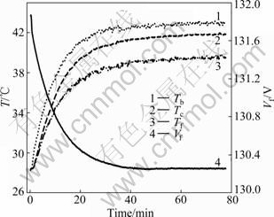
Fig.4 Startup performance of flat heat pipe radiator
The thermal resistance variation of the flat heat pipe radiator at different input powers is shown in Fig.5. When the input power increases from 46.0 W (0.35 A) to 83.2 W (0.6 A), the total thermal resistance of the flat heat pipe radiator (Rt) decreases from 0.45 K/W to 0.38 K/W. The total thermal resistance of the flat heat pipe radiator (Rt), the thermal resistance of the FHP (Rhp), and the thermal resistance of natural convection (Rcon) decrease with the increase of input power. With increasing heat loads, the mass flow rate of vapor increases, which enhances the rate of heat transfer and temperature uniformity of FHP. Therefore, the thermal resistance becomes lower.
Fig.6 illustrates the comparison of junction temperature of LED array with the flat heat pipe radiator and with the aluminum board at different heat loads. The junction temperature is found to drop significantly by utilizing the flat heat pipe radiator. The junction temperatures with the flat heat pipe radiator and with the aluminum board at the same forward current of 0.35 A are 52.5 and 75.2 °C, respectively. Moreover, the difference of junction temperature with the flat heat pipe radiator and with the aluminum board at the same forward current increases gradually with increasing the forward current. Lowering the junction temperature of LED chips by utilizing the flat heat pipe radiator directly indicates higher flux of light and longer lifetime compared with the LED array with the aluminum board.
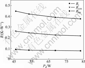
Fig.5 Curves of thermal resistance vs input power
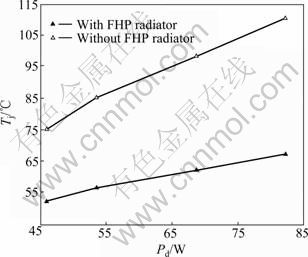
Fig.6 Comparison of junction temperature of LED array without and with FHP radiator
Fig.7 represents the effect of the incline angle on the thermal resistance of the flat heat pipe radiator at the forward current of 0.35 A. The thermal resistance increases with the increase of the incline angle. When the incline angle increases from 0° to 45°, the total thermal resistance of flat heat pipe radiator (Rt) increases from 0.45 to 0.48 K/W. Increasing the incline angle can increase the flow resistance of air, which decreases the heat transfer coefficient of the natural convection between fins and the surroundings. However, the relative change rate of Rt is only 6.16%. Therefore, the incline angle has little effect on the thermal characteristics of the flat heat pipe radiator. It is noteworthy that the thermal resistance of the natural convection accounts for about 60% of the total thermal resistance of the flat heat pipe radiator. The thermal resistance of natural convection between the fins and the surroundings can be decreased via the optimal design of the pitch and height of the fins.
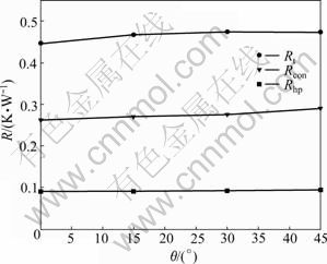
Fig.7 Curves of thermal resistance vs incline angle
Fig.8 shows the integral steady temperature distribution of the flat heat pipe radiator at the forward current of 0.35 A. The temperature decreases gradually from the substructure, the FHP to the fins. The maximum temperature difference of the condenser of the FHP is below 2 °C. The flat heat pipe radiator has a reasonable and uniform temperature distribution, and has a high heat dissipation capacity.
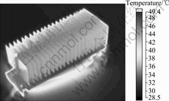
Fig.8 Integral temperature distribution of flat heat pipe radiator
6 Conclusions
1) An innovative flat heat pipe radiator is put forward, and it has the features of high efficiency of heat dissipation, compact construction, low thermal resistance, light weight, low cost, and anti-ash-deposition.
2) The total thermal resistance of the flat heat pipe radiator varies in the range of 0.38-0.45 K/W and it has a reasonable and uniform temperature distribution.
3) The junction temperatures with the flat heat pipe radiator and with the aluminum board at the same forward current of 0.35 A are 52.5 and 75.2 °C, respectively.
4) The innovative flat heat pipe radiator can effectively decrease the total thermal resistance of LED system, and is proved to be very promising for the thermal management of LED devices.
References
[1] HWU F S, SHEU G J, CHEN J C. Thermal modeling and performance of LED packaging for illuminating device [C]// 6th SPIE Inter Conf on Solid State Lighting. San Diego, USA, 2006: J1-J6.
[2] ACIKALIN T, GARIMELLA S V, PETROSKI J, RAMAN A. Optimal design of miniature piezoelectric fans for cooling light emitting diodes [C]// 9th IEEE Intersociety Conference on Thermal and Thermomechanical Phenomena in Electronic Systems. New York, USA, 2004: 663-671.
[3] MA H K, CHEN B R, LAN H W, LIN K T, CHAO C Y. Study of an LED device with vibrating piezoelectric fins [C]// 25th IEEE SEMI- THERM Symposium. CA, USA, 2009: 267-272.
[4] CHAU S W, LIN C H, YEH C H, YANG C. Study on the cooling enhancement of LED heat sources via an electrohydrodynamic approach [C]// 33rd Annual Conference of the IEEE Industrial Electronics Society. Taipei, 2007: 2934-2937
[5] MA Ze-tao, WANG Xiao-jun, ZHU Da-qing, LIU Sheng. Thermal analysis and modeling of LED arrays integrated with an innovative liquid-cooling module [C]// 6th IEEE Inter Conf on Electronic Packaging Technology. Shenzhen, China, 2005: 1-4.
[6] LUO Xiao-bing, LIU Sheng. A microjet array cooling system for thermal management of high-brightness LEDs [C]// IEEE Transactions on Advanced Packaging. New York, USA, 2007: 475- 484.
[7] CHENG J H, LIU C K, CHAO Y L, TAIN R M. Cooling performance of silicon-based thermoelectric device on high power LED [C]// 24th IEEE International Conference on Thermoelectrics. University of Clemson, USA, 2005: 53-56.
[8] LIU C K, DAI M J, YU C K, KUO S L. High efficiency silicon-based high power LED package integrated with micro-thermoelectric device [C]// IEEE International Microsystems, Packaging, Assembly and Circuits Technology Conference. 2007: 29-33.
[9] SHEU G J, HWU F S, TU S H, CHEN W T, CHANG J Y, CHEN J C. The heat dissipation performance of LED applied a MHP [C]// 5th SPIE International Conference on Solid State Lighting. San Diego, USA, 2005: 1-8.
[10] KIM L, CHOI J H, JANG S H, SHIN M W. Thermal analysis of LED array system with heat pipe [J]. Thermochimica Acta, 2007, 455: 21-25.
[11] LIN S C, HONG J T, TSAI M L, SHIH H C, LEONG J C, CHEN W L. Thermal management of the LED headlamp module for a motorcycle [C]// 40th AIAA Thermophysics Conference. Washington, USA, 2008: 4252.
[12] LU Xiang-you, HUA Tse-Chao, LIU Mei-jing, CHENG Yuan-xia. Thermal analysis of loop heat pipe used for high power LED [J]. Thermochimica Acta, 2009, 493: 25-29.
[13] ARIK M, WEAVER S. Chip scale thermal management of high brightness LED packages [C]// 5th SPIE Inter Conf on Solid State Lighting. Denver, USA, 2004: 214-223.
[14] SHIN M W. Thermal design of high-power LED package and system [C]// SPIE Advanced LEDs for Solid State Lighting. Gwangju, South Korea, 2006: 635509.
(Edited by YANG Bing)
Foundation item: Project(50876016) support by the National Natural Science Foundation of China
Received date: 2009-12-31; Accepted date: 2010-05-10
Corresponding author: BAI Min-li, Professor, PhD; Tel: +86-411-84706305; E-mail: baiminli@dlut.edu.cn

