Planing process of fin heat sinks
TANG Yong(�� ��)1, CHI Yong(�� ��)1, LIU Xiao-kang(������)1,
LIU Xiao-qing(������)1, WAN Zhen-ping(����ƽ)1, LIU Ya-jun(���ǿ�)1, XIONG Cai-hua(�̻ܲ�)2
(1. College of Mechanical Engineering, South China University of Technology, Guangzhou 510640, China;
2. School of Mechanical Science and Engineering, Huazhong University of Science and Technology, Wuhan 430074, China)
Abstract: Based on analyzing the traditional process to manufacture fin heat sinks(FHS), the production of FHS by the planing process was proposed, the mechanism of the fins�� curl was investigated and the fins�� surface finish was analyzed. Through controlling chip curl based on the continuous strip chips, flat straight fins were processed. Compared with the traditional processes, this process makes full use of material and the processed FHS has better heat transfer capacity, higher heat transfer efficiency and more reliability. The tool geometrical parameters and processing performance affect the fins�� curl. The optimum processing parameters are: a cutter edge inclination angle of 0��, a rake angle between 50�� and 55��, and a planing depth from 0.2mm to 0.3mm. The planing speed has little effect on the fins�� curl.
Key words: fin heat sink(FHS); planing-forming; fin curl; down-curl CLC number: TG55
Document code: A
1 INTRODUCTION
There are lots of traditional processes for fin heat sinks(FHS), such as cold-extruding, welding, cold-rolling and cold-forging. The cold-extruding process calls for strict requirements for the molds because the deformation press is very big and the machined fins are usually too thick. The welding process is complex and costly, but not reliable, because the welding line is dampened in the application, and it��s easy to be damaged when two different metals electrolyze in water. Once the welding line is damaged, there will be interlayer of air between the tube and the fins, which increases the heat resistance and decreases the heat transfer capability. The cold-rolling process is usually limited to manufacturing the tubular FHS. And finally because the tools and molds have serious wear in the cold-forging process, which results in large operating costs, it is seldom used in manufacturing fins.
In this paper the authors propose a new planing-forming process, which processes the fins by planing the workpiece with specially designed tools. Based on forming continuous strip chips, by controlling the chip��s flow direction and curling radius, the straight fin piece is obtained successfully. Compared with the traditional ways of machining fins, this process is simple and easy, and requires less equipment. The produced fins are thinner, only 0.2mm. The space between two fins can be narrower and the quantity of the fins can be greater, so the heat transfer area per unit is enlarged. Moreover, because the fin root and the base are a single piece, this avoids damage as the welding lines are easily electrolyzed even when damp. So the fins machined by the planing process have better transfer heat capability, higher transfer heat efficiency and more reliability.
There are many different chip structures, such as continuous strip chips, segmented chips, grainy chips and broken chips. Some researchers[1-5] have studied the forming conditions of each. The continuous strip chips can be obtained from cutting metals of excellent plasticity by tools with a big rake angle. Other researchers[6-13] have investigated the factors causing chips to curl, for example the material performance, the geometrical shape and parameters of the tool and the process performance. In this paper the effect of the tool��s geometry and process performance on the fin��s curling direction and radius was studied to find out the optimum parameters, make the fins flat and straight, and manufacture top-quality FHS.
2 EXPERIMENTAL
In order to obtain flat, straight and regular shape fins, one must first assure that the chips are continuous strips. Then the chips are formed into fins by controlling the chip��s curling. Because the chips become a part of the workpiece, they make full use of the materials.
Fig.1 illustrates the experiment device. The experiments were done on a universal planer. A slide track between the worktable and the jig allows the workpiece to move along the x axis and feed in that direction. The stroke is first adjusted according to the process parameters so the fin won��t be separated from the base. The planing tool reciprocates and plans the workpiece made of aluminum, 1145, annealed. One fin is made in each reciprocating movement, and when a movement is finished, the worktable moves up and backwards and feeds once. The upright feed ��y determines the fin��s thickness. ��x is determined by both ��y and ��. The relationship among the three parameters is
��x=��ycot��(1)
where ��x is the feed in x direction, ��y is the feed in y direction, and �� is the incline angle of the workpiece.
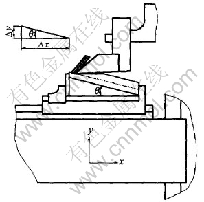
Fig.1 Illustration of experimental device
The space between two fins, ��p, can be calculated by
In fact, the workpiece inclination, ��, determines the space between two fins. The bigger this angle is, the smaller the space is, the thicker the fins are, and the bigger the angle between the fins and the base is. Based on the targeted fin thickness and space, a reasonable fixed angle can be found.
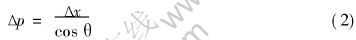
The planed fins are not perpendicular to the base, so they must be realigned to become perpendicular to the base. To do this, first, a rubber piece is used to press the end of the fins to make sure it occludes them; then, the rubber piece is pushed to force all the fins perpendicular to the base, as shown in Fig.2.
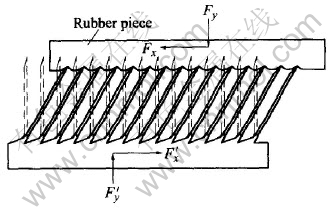
Fig.2 Illustration of realigning fins
Fig.3 shows the planning tool, which is made of W18CrMoAl with the clearance angle, ��, of 3��. The tool and the shank are welded together by brazing. Through experiments using different level factors of the tool rake angle, the cutting edge inclination angle, the planing depth and the velocity, the optimum range of each parameter can be found, which can provide the basis for the planing process of FHS and the tool design.
Fig.3 Structure of planing tool
3 RESULTS AND DISCUSSION
3.1 Curl of fins
The fin curls during planing, which affects its quality greatly. In order to obtain ideal FHS, it is essential to restrain the curl. Generally, it occurs in two directions: side-curl and up-curl, as shown in Fig.4. It leads to a compounded curl if the two types happen at the same time. According to kinematics, the velocity gradient in the direction of the width results in side-curl, while the velocity gradient in the direction of the depth results in up-curl. There are many factors causing the fins to curl. This paper discusses the effects of the tool geometrical parameters and the processing parameters.
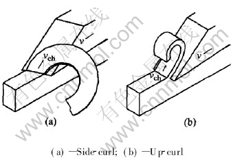
Fig.4 Curl of fins
3.1.1 Effect of tool edge inclination on fins�� side-curl
The inclination of the cutting edge is the main factor causing the fins to side-curl. Fig.5 shows the effect of cutting edge indination angle on fins�� side-curl. In this test the rake angle was set at 55��, the clearance angle at 3��, the cutting speed at 48mm/s and the cutting depth at 0.3mm. The curliness curvature increased as the tool cutting edge inclination increased. The smaller the curliness curvature, the straighter the fins were. When the cutting edge inclination was 0��, the fins didn��t side-curl.
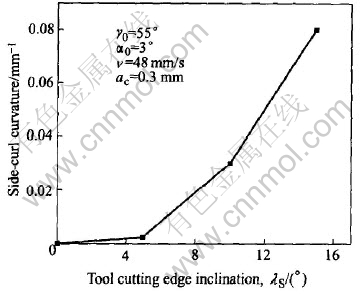
Fig.5 Effect of cutting edge inclination angle on fins�� side-curl
3.1.2 Effect of tool rake angle on fins�� up-curl
As shown in Fig.6, the rake angle has the most evident influence on the up-curl. In this test, the cutter edge inclination angle was set at 0��, the clearance angle at 3��, the cutting speed at 48mm/s and the cutting thickness at 0.3mm. The up-curl curvature decreased as the tool rake increased. The larger the tool rake, the flatter the fins were. Considering the tool strength, the optimum range of the tool rake angle was between 50�� and 55��. In this range, the cutter not only has enough strength, but also has reduced up-curl.
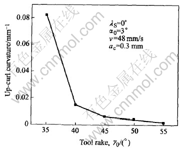
Fig.6 Effect of rake angle on fins�� up-curl
3.1.3 Effect of planing depth on fins�� up-curl
The cutting thickness has bigger influence on the up-curl. Fig.7 shows its effect under the experimental condition that the cutting edge inclination angle was set at 0��, the rake angle at 55��, the clearance angle at 3�� and the cutting speed at 48mm/s. The up-curl curvature decreased as the planing depth increased. Obviously, increasing the planing depth can restrain the fins�� up-curl. However, the fin shouldn��t be too thick due to its structural and functional requirements. Its optimum range was from 0.2mm to 0.3mm, where it not only raised the heat transfer efficiency of the fins, but also reduced the effect of the planing depth on the up-curl.
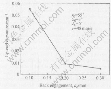
Fig.7 Effect of planing depth on fins�� up-curl
3.1.4 Effect of planing speed on fins�� curliness
In this test, the cutting edge inclination angle was set at 0��, the rake angle at 55��, the clearance angle at 3�� and the planing depth at 0.3mm. Fig.8 shows that the variation in planing speed has little effect on the up-curl. So the planing speed can be much higher.
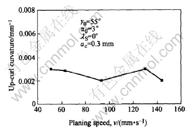
Fig.8 Effect of planing speed on fins�� up-curl
3.1.5 Analysis of curl mechanism
There are no definite conclusions on the mechanism of the chips�� nature curl. Ponkshe thought that the residual strain in the chips results in the curl. The materials go through uneven plastic deformation, so the uneven strain remains at the boundary between the plastic deformation area and the chips�� rigid area. These distribution gradient of residual strain makes the chips curl. By deducing the cutting equation from slippage, Lee and Shaffer[14] considered the curl resulted from the residual stress and heat deformation as the cutting temperature rose. Albrecht et al reckoned the flexural torque resulted from the uneven force on the shear plane and rake face was the reason for curl.
In the planing experiments, in addition to up-curl, a new curl (down-curl) was discovered, as shown in Fig.9. Flat and straight fins are the optimum result and occur when the fin has a uniform residual strain along the shear plane in planing. Because the inner-layer of the metal is not only deformed, but also subjected to friction and extrusion from the rake face, there is an uneven residual strain along the depth direction in the fins. The residual strain is bigger in the area near the rake face, while near the free surface, it is smaller. After parting from the rake face, the fins curl upwards owing to the distribution gradient of the residual strain. Whereas the residual strain area near the rake face is smaller, and near the free surface is much bigger, the fins will curl downwards. Down-curl is seldom seen in cutting, and further research needs to be done to determine the distribution of the stress-strain and the cause.
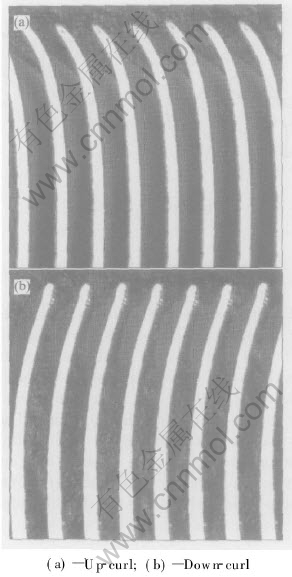
Fig.9 Curl of fins
3.2 Quality of fins
3.2.1 Structure and heat transfer capability of fins
Fig.10 shows FHS produced by the planing process when the cutting edge inclination angle was set at 0��, the rake angle at 55��, the clearance angle at 3��, the cutting speed at 48mm/s and the planing depth at 0.3mm.
In these conditions, the curl radius was very big, almost close to infinity and the fins curl downwards a little. The space between two fins, the fin thickness and the length are uniform. The planing-formed FHS has the following characteristics: the ratio of height to width is big, the heat resistance is small, and the fins are as thin as 0.2mm. Because the space between two fins is narrow, there are more fins in the same base. As shown in SEM images, there is no crack between the fins and the base. Obviously, the deformation is plastic, so the fins directly connect with the base. Compared with the welding process, this process can effectively prevent double metals from electrolyzing in damp, so FHS has higher reliability. Due to the plastic deformation, the reduction in the fin��s length results in an increase in the width and the thickness. But the width increment is so small that it can be neglected. The available length and thickness of the fins can be adjusted by processing parameters.
According to Fourier heat transfer theory, the heat transmitted in unit time is

where Q is the heat transfer rate, ��t is the temperature difference between two side of plane wall, and �� is the thickness of plane wall, F is the area of plane wall, and �� is the coefficient of heat conductivity.
The heat transfer velocity increases as the heat radiation area increases and the thickness reduces. Obviously the heat transfer efficiency of FHS machined by planing can be improved effectively because of the higher height-to-width ratio, the thinner fins, smaller space, etc. In order to improve the distribution of the heat flow density, different configurations of the fin surface can be obtained by changing the shape of the materials, therefore the heat transfer efficiency can be further improved.
3.2.2 Surface finish of fins
The two surfaces of the planing-formed fins have different finish. Fig.11 shows the SEM images. The surface contacting with the rake face has a smoother glossy finish (Fig.11(a)), but the one away from the tool is rather rough, with lanose wrinkles and distinct tool marks along the feeding direction (Fig.11(b)).
The surface contacting the tool is subjected to compression stress. In the planing process, the extrusion, friction and scraping from the rake face act on this surface. Simultaneously, the second deformation area makes the surface metal detained and the grain fiberized, thus this surface is smooth. As shown in Fig.11(a), the surface has several micro-grooves along the direction the tool moves. The edge��s plainness, the roughness of the rake face and the friction from the rake face directly affect the quality of this surface. 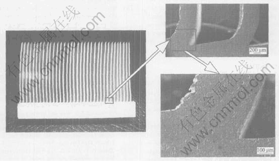
Fig.10 Zoom of planing-formed FHS and its SEM microstructure
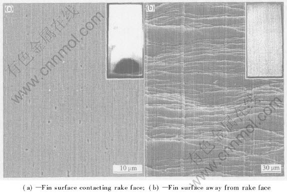
Fig.11 Two surfaces of fin
While on the other side, there are not only micro-grooves parallel to the direction the tool moves, but also distinct squamae wrinkles perpendicular to them, in general because the machining fins are subjected to shearing deformation. In planing, the plainness of the edge and the friction from the tool flank results in micro-grooves on the machined surface. Meanwhile, some squamae appear on the machined surface. When the next fin is being formed, the previously machined surface becomes the surface away from the tool surface. The metal in first deformation area suffers shear deformation so the fin becomes thick and short. The lanose wrinkles result from the free surface shrinking. At the same time, the shrinking in the length makes the squamae denser and the grooves more distinct, so the surface is rougher. Moreover, the metal grains near the shear surface slip along the slipping plane and the grains become longer, which also increases the roughness of the surface. But in HFS, rough surface has more surface area than a smooth one, so the heat exchange area is increased, which can improve heat transfer ability.
4 CONCLUSIONS
1) Based on continuous strip chips, and by controlling the chips�� curl, the chips are turned into fins, which can make full use of the material. The FHS machined by this planing process have higher heat transfer efficiency.
2) The planing process of FHS is practicable. Ideal fins are produced successfully by the planing process when the cutting edge inclination angle is set at 0��, the rake angle at 55��, the clearance angle at 3��, the cutting speed at 48mm/s and the cutting depth at 0.3mm.
3) The cutting edge inclination angle is the main factors affecting the fins�� side-curl. The bigger the angle is, the worse the curl is. When the angle is 0��, the fins don��t curl sideward, so it��s the optimum value.
4) The tool rake angle and the planing thickness are the main factors causing up-curl. The planing speed has little effect on the fins�� curl. The up-curl curvature decreases as the tool rake angle and the planing thickness increases. Owing to the tool��s strength, the optimum range of the tool rake angle is between 50�� and 55��. The planing thickness is from 0.2mm to 0.3mm.
REFERENCES
[1]Bouzakis K D, Aichouh P, Efstathiou K. Determination of the chip geometry, cutting force and roughness infree form surfaces finishing milling, with ball end tools [J]. Int J Mach Tools Manuf, 2003, 43: 499-514.
[2]Lin G C I, Oxley P L B. Mechanics of oblique machining: predicting chip geometry and cutting forces from work material properties and cutting conditions [J]. Proc Ins Mech Eng, 1972, 186: 813-820.
[3]Lin G C I. Prediction of cutting forces and chip geometry in oblique machining from flow stress properties and cutting conditions [J]. Int J Mach Tool Des Res, 1978, 18: 117-130.
[4]Bradley H J, Thomas A D. Investigation and prediction of chip geometry in diamond turning [J]. Prec Eng, 2000, 24: 88-96.
[5]Strenkowski J S , Moon K J. Finite element prediction of chip geometry and tool/workpiece temperature distributions in orthogonal metal cutting [J]. ASME J Eng Ind, 1990, 112: 313-318.
[6]Strenkowski J S, Athavale S M. A partially constrained eulerian orthogonal cutting model for chip control tools [J]. ASME J Manuf Sci Eng, 1997, 119: 681-688.
[7]Cook N H, Jhaveri P, Nayak N. The mechanism of chip curl and its importance in metal cutting [J]. Trans ASME, 1963, 85(B): 374-380.
[8]Hahn R S. Some observations on chip curl in the metal-cutting process under orthogonal cutting conditions [J]. Trans ASME, 1953, 75: 581-590.
[9]Pekelharing A J. Why and how does the chip curl and break [J]. Ann CIRP, 1964, 12(3): 55-58.
[10]Worthington B. The effect of rake face configuration on the curvature of the chip in metal cutting [J]. Int J Mach Tool Des Res, 1975, 15: 223-239.
[11]Zhang H T, Liu P D, Hu R S. The theoretical calculation of naturally curling radius of chip [J]. Int J Mach Tools Manuf, 1989, 29(3): 323-332.
[12]Fang N, Jawahir I S. Prediction and validation of chip up-curl in machining using the universal slip-line model [J]. Trans NAMRC/SME, 2000, 28: 137-142.
[13]Nakayama K. Origins of side-curl of chip in metal cutting [J]. Oper Sect Proc Am Gas Assoc, 1972, 6(3): 99-101.
[14]Lee E H, Shaffer B W. The theory of plasticity applied to a problem of machining [J]. J Appl Mech Sci, 1951, 7: 43.
[15]Ramaswamy C, Joshi Y, Nakayama W, et al. Effects of varying geometrical parameters on boiling from microfabricated enhanced structures [J]. J Heat Trans, 2003, 125(2): 103-109.
(Edited by YUAN Sai-qian)
Foundation item: Projects(50436010; 50375055; 50175028) supported by the National Natural Science Foundation of China; Project(04105942) supported by the Natural Science Foundation of Guangdong Province, China
Received date: 2004-12-09; Accepted date:2005-03-08
Correspondence: TANG Yong, Professor, PhD; Tel: +86-20-87114634, Fax: +86-20-87114634; E-mail: ytang@scut.edu.cn

