�������ϲ��Ͻ���Ħ���������н������ĥ��Ԥ��
��Դ�ڿ����й���ɫ����ѧ��(Ӣ�İ�)2016���8��
�������ߣ�Ashish BIST J. S. SAINI Bikramjit SHARMA
����ҳ�룺2003 - 2018
�ؼ��ʣ�����Ħ�������������ϲ��ϣ�����ĥ��
Key words��friction stir welding; aluminium matrix composites; tool wear
ժ Ҫ������Ħ�������������ϲ�����ѡ�ĺ��ӷ���������һ�ֹ�̬���ӷ��������Է�ֹ�ۺ����γɵĽ����仯���ﵼ����ѧ�����½�������Ħ��������Ҫ�������ǽ������ĥ��ĥ�������ڽ������븴�ϲ�����Ӳ����ǿ��ڽӴ�����ɵġ����������˲�ͬ����Ħ���������Խ�����ĥ���Ӱ�졣�о����֣�������IJ���ĥ������������ת�ٺͺ��ӳ��ȳ����ȣ����н��ٶȳʷ��ȡ�������ļ�����״Ҳ��ĥ����������ء���������������ת������Ż���״�Լ�Сĥ��
Abstract: Friction stir welding is the preferred joining method for aluminium matrix composites. It is a solid-state process which prevents the formation of the intermetallic precipitates responsible for degradation of mechanical properties in fusion welds of these composites. The major concern in friction stir welding is the wear of the welding tool pin. The wear is due to the prolonged contact between the tool and the harder reinforcements in the composite materials. This paper provides an overview of the effects of different parameters of friction stir welding on the tool wear. It was found that the total amount of material removed from the tool is in direct proportion to the rotational speed of the tool and the length of the weld but inversely proportional to the transverse rate. The results even demonstrate that the tool geometry also has significant influence on the wear resistance of the tool. The tool even converts itself into a self-optimized shape to minimize its wear.
Trans. Nonferrous Met. Soc. China 26(2016) 2003-2018
Ashish BIST1, J. S. SAINI2, Bikramjit SHARMA2
1. Mechanical Engineering Department, Graphic Era University, Dehradun 248002, Uttarakhand, India;
2. Mechanical Engineering Department, Thapar University, Patiala 147004, Punjab, India
Received 8 September 2015; accepted 17 February 2016
Abstract: Friction stir welding is the preferred joining method for aluminium matrix composites. It is a solid-state process which prevents the formation of the intermetallic precipitates responsible for degradation of mechanical properties in fusion welds of these composites. The major concern in friction stir welding is the wear of the welding tool pin. The wear is due to the prolonged contact between the tool and the harder reinforcements in the composite materials. This paper provides an overview of the effects of different parameters of friction stir welding on the tool wear. It was found that the total amount of material removed from the tool is in direct proportion to the rotational speed of the tool and the length of the weld but inversely proportional to the transverse rate. The results even demonstrate that the tool geometry also has significant influence on the wear resistance of the tool. The tool even converts itself into a self-optimized shape to minimize its wear.
Key words: friction stir welding; aluminium matrix composites; tool wear
1 Introduction
Particulates reinforced aluminium matrix composites (AMC) are considered as one of the most promising structural materials for advanced applications in aerospace, military and transportation industries [1]. However, in order to produce larger or more complex structural components, it is inevitable to join AMCs to themselves or other materials. Therefore, some joining processes such as fusion welding [2-4], brazing [5] and diffusion bonding [6-8] were developed, but they resulted, to different extent, in the degradation of mechanical properties. Friction stir welding (FSW) is considered as a prospective joining process to solve this problem. As a solid-state joining process, FSW can eliminate the welding defects associated with fusion welding processes [9]. During FSW, the joining of plates takes place below the melting point of the materials. The maximum temperature reached during the process is 80% of the melting temperature of the work pieces. The welds are created by the combined action of frictional heating and mechanical deformation due to a rotating tool. The detrimental effects of arc welding such as distortion and residual stresses are due to the rapid heating beyond the melting temperature and cooling of the joints. These detrimental effects are minimized in FSW, as the heat generated is not severe enough [10].
1.1 FSW process
FSW is a joining technique developed by The Welding Institute (TWI) of Cambridge, England, in 1991 [11]. In FSW, a cylindrical, shouldered tool with a profiled probe, shown in Fig. 1, is rotated and slowly plunged into the joint line between two pieces butted. FSW process with a schematic diagram is shown in Fig. 2. The parts have to be clamped onto a backing bar in a manner that prevents the abutting joint faces from being forced apart. The tool serves two primary functions: heating of work piece, and movement of material to produce the joint. Contact of the pin with the work piece creates frictional and deformational heating and softens the work piece material; contacting the shoulder to the work piece increases the work piece heating, expands the zone of softened material, and constrains the deformed material [14]. The plasticized material is transferred from the leading edge of the tool to the trailing edge of the tool probe and is forged by the intimate contact of the tool shoulder and the pin profile. As a result of this process, a joint is produced in ��solid state�� [13].
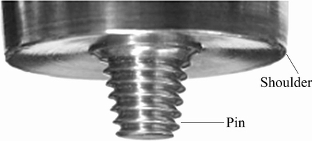
Fig. 1 Parts of FSW tool [12]
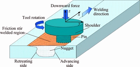
Fig. 2 Schematic drawing of FSW [13]
According to the microstructural evolutions, there are three zones in the welding zone: stirring zone (SZ), heat-affected zone (HAZ) and thermo-mechanical affected zone (TMAZ) [15-18]. SZ is characterized by fine and equiaxed grains. TMAZ includes elongated and recovered grains. But, HAZ is identified only by the hardness result because there is no obvious difference in grain structure compared to the base metal [19]. The onion rings formed in the stirring zone is found to be the results of the combination of the slight grain size variations and a change in nature and size of the particles, i.e., intra vs intergranular [20]. One of the major benefits of FSW is that it has significantly fewer process elements to control as compared to fusion weld which is controlled by purge gas, voltage, wire feed, traverse speed, shield gas and arc gap. The increase in joint strength combined with the reduction in process variability provides an increased safety margin and high degree of reliability [21].
It is well known that the main challenge in any of the welding process for the manufacturer is to select the optimum welding parameters which would produce an excellent welded joint [22]. FSW process is controlled by rotational speed, welding or transverse speed, axial force, tool geometry and tool tilt angle. The tool geometry includes pin length, pin diameter, tool shoulder diameter, ratio of tool shoulder diameter and pin diameter of the tool [23].
The rotational speed helps in stirring, mixing of material and generating the frictional heat, transverse speed controls the heat as well as reason of appearance of weld generated, axial force helps in maintaining contact conditions and generates the frictional heat and the tilting angle helps in thinning and appearance of the weld. Further, the plunge depth of pin into the work pieces (also called target depth) is important for producing sound welds with smooth tool shoulders. The welding speed prompts the translation of tool which in turn pushes the stirred material which arises due to the tool rotation from front to the back of the tool pin and completes the welding. The rubbing of tool shoulder and pin with the work piece generates the frictional heat [24]. Working range of each parameter is decided upon by inspecting macrostructure (cross section of weld region) for a smooth appearance without any visible defects such as pinhole, tunnel defect, crack, void, surface groove and surface galling. It has been observed that when tool rotation speed is lower than 1000 r/min, tunnel defect is at the middle of retreating side of weld region which may be due to insufficient heat generation and insufficient metal transportation. When tool rotation speed is higher than 1400 r/min, tunnel defect is observed at the top of retreating side which may be due to excess turbulence caused by higher tool rotation speed. When welding speed is lower than 22 mm/min, tunnel defect is observed at retreating side due to excess heat input per unit length of weld. When welding speed is higher than 75 mm/min, tunnel at retreating side and middle of weld region is observed due to inadequate flow of material causes by insufficient heat input. When axial force is lower than 2 kN, pin hole defect at retreating side is observed due to the absence of vertical flow of material caused by insufficient axial force. When axial force is increased beyond 4 kN, it results in tunnel defect at both sides of retreating and advancing and excessive thinning due to higher heat input [25]. A fully coupled thermo-mechanical model is adopted to study the effect of shoulder size on the temperature distributions and the material deformations in FSW. Numerical results indicate that the maximum temperature can be increased with the increase of the shoulder diameter. The stirring zone can be enlarged by the increase of the shoulder size [26]. It is observed that increasing rotational (��) and traverse speed (v) ratio increases the weld nugget size and decreases the incomplete root penetration. By increasing ��/v ratio, a slight decrease in the effective tensile properties calculated from shear punch test (SPT) of different zones is observed. That is due to increased heat input and softening of the material in these regions. Furthermore, increasing ��/v ratio results in the formation of a larger weld nugget due to an increase in heat input and an easier material flow. Therefore, the probability of formation of ����incomplete root penetration���� defect is reduced with increase in ��/v ratio [27].
1.2 Joining of AMC
AMCs have received considerable attention over the past 30 years due to their significant properties. Aerospace industry goals have called for reduced weight in different space-based structures [28]. AMCs offer several potential benefits to help the industry to meet this goal. Weld ability of these composites is significantly reduced due to the addition of ceramic reinforcements. It is hard to achieve defect-free AMC welds. The drawbacks associated with the fusion welding include: 1) the incomplete mixing of the parent and filler materials; 2) the presence of porosity as large as 100 ��m in the fusion zone; 3) the excess eutectic formation and 4) the formation of undesirable deleterious phases such as Al4C3 [29]. It is generally known that the fusion- welding processes often lead to the deterioration of these composites. In the case of Al2O3 reinforced composites, the Al2O3 decomposes to aluminum and gas in contact with liquid aluminum [30]. Similarly, in the case of SiC-reinforced composites, the SiC reacts with molten aluminum to form Al4C3 carbide [31]. The literature shows that the tendency toward the formation of Al4C3 can be reduced in certain arc welding conditions [30]. During laser welding, it is very difficult to avoid these decompositions. However, DAHOTRE et al [32] showed that decreasing the specific energy during laser melting could reduce the formation of Al4C3. These defects can be reduced or eliminated through careful control of the heat input in a solid-state joining process such as FSW [29]. FSW process eliminates all the fusion welding problems. However, the presence of hard ceramic reinforcement particles in the composites offers high wear resistance which affects the weld quality. The material flow behavior of composites during FSW process greatly depends on the welding parameters, tool design and the amount of reinforcement. The weld temperature and rotation of tool also influence the particle size, shape and distribution in the weld zone [33].
FSW is very much preferred for joining unweldable aluminum alloys such as the 2xxx and 7xxx series used in aircraft structures. The strength of the weld is 30%-50% higher than that of arc welding. The fatigue life is comparable to that of riveted panels. As FSW becomes better established, it has the capability to replace plasma arc welding (PAW) and electron beam welding (EBW) in some specific applications in aluminum and titanium respectively. The wrought aluminum alloy joints fabricated by FSW exhibit higher strength values which are approximately 34% higher compared to those of the gas metal arc welding (GMAW) joints and 28% higher compared to those of the gas tungsten arc welding (GTAW) joints. FSW can potentially replace the riveting and resistance spot welding of aluminum and steel sheets in the aircraft and automotive industries, respectively [34].
The major barrier in FSW is the wear of the welding tool pin. Tool wear in FSW depends on number of parameters such as tool geometry, rotational speed, traverse speed and travel distance. Wear in this process can be controlled by the careful selection of these parameters. The present paper gives the review of the effect of these parameters on the wear of the tool pin.
2 Wear of FSW tools in joining of AMCS
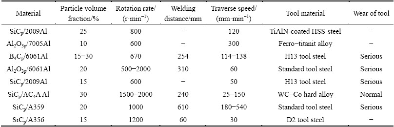
FSW tools made from conventional materials have a nearly infinite life when used to join aluminum alloys. But they exhibit wear in the welding of harder materials such as composites and steel [35]. The amount of wear of a particular tool will experience during an AMC weld is hypothesized to vary inversely with the hardness ratio H, a dimensionless metric which defines the hardness of the tool material (Ht) to that of the reinforcement (Hr). When H is less than 1, the hardness of the reinforcement exceeds the hardness of the tool (Hr >Ht). For these cases, an increase in the hardness ratio (accomplished by decreasing the hardness of the reinforcement or increasing the hardness of the tool) shall correspond to a proportional decrease in the amount of the tool wear. Tool wear cannot occur when the hardness ratio is greater than 1, as the hardness of the tool is greater than that of the reinforcing material (Ht>Hr) [36]. Tool wear in FSW is an undesirable feature because erosion of the probe features and/or probe length inhibits the flow of material (particularly in the vertical direction), which in turn increases the likelihood of defect formation. For instance, a reduction in the length of the probe as a consequence of wear often creates a lack of consolidated material (void) at the base of the joint known as the root flaw defect [37]. Excessive tool wear changes the tool shape, thereby increasing the probability of defect generation, and possibly degrading the weld quality. The exact wear mechanism depends on the interaction between the work piece and the tool materials, the selected tool geometry and the welding parameters. For example, in the case of polycrystalline cubic boron nitride (PCBN) tools, the wear at low tool rotation rate is mainly caused by adhesive wear (also known as scoring, galling or seizing), while the wear at high tool rotation rate is due to abrasive wear [14,38]. The challenge in the welding of AMCs using FSW is thus to maintain wear below an experimentally determined threshold where the probability of defect formation becomes unacceptable and, in instances where deterioration can not be confined to the low-wear regime over the course of the weld, and to replace the tool before it attains this critical value of wear. Table 1 shows the wear of tools having different materials during FSW of different composite materials at different parameters [39].
Table 1 Tool wearing of various FSW AMC joints achieved at different parameters [39]
2.1 Quantification of FSW tool abrasion
The tool material eroded as a result of contact with hard reinforcing particles is deposited along the joint line. This abraded material can be detected and quantified [35]. In order to quantitatively assess the tool wear, LIU et al [9] used the percent variation (rw), given by Eq. (1), in tool size as evaluation index.
 (1)
(1)
where d0 is the original size and dm is the measured size.
PRATER et al [36] quantified the wear by measuring changes in the weight of the probe inserts as a result of wear. Inserts were removed after each weld, analyzed, and re-inserted prior to the next experiment in the series because aluminum accumulated on the probe surface during welding. The insert was immersed in a solution of NaOH and water until all the aluminum are eroded from the surface. Percent wear (Rw) was calculated using Eq. (2).
 (2)
(2)
where mi denotes the initial mass of the probe and ��m is the change in mass of the probe insert.
FERNANDEZ and MURR [40] measured wear by capturing close-up images of the tool probe, cutting out the probe in these images, and comparing the masses of the cutouts. The assumption that the mass of the two-dimensional image cutout is indicative of the tool��s material loss is substantiated by a series of parallel experiments which calculated the percent wear by comparing masses of the etched tool after each weld. PRATER et al [41] used the optics bench and took close-up images of the probe using a Canon A620 Power shot camera. These images were imported into the imaging software, where the wear of the probe was quantified by comparing pre-weld images of the probe with those taken after a given weld traverse distance. The percent tool loss (RL) is calculated using Eq. (3).
 (3)
(3)
where P represents the original pixel count of the probe and P�� represents the probe��s pixel count after some weld distance. A 1 cm square grid fixed behind the tool was used to convert measurements from pixels to square centimeters.
MAHMOOD et al [42] used an electronic digital balance with 0.1 mg accuracy to measure the initial and final mass of the specimen. The masses of all the specimens were measured before and after running. The tests were carried out for 3 h; then the specimens were removed from the wear testing machine and cleaned with alcohol, in order to remove all the attached worn particles, and then the mass of the specimen was measured to determine the mass loss. The wear rates were determined using the volume loss method, as given by Eq. (4).
 (4)
(4)
where W is the volume loss during test period (cm3/m), M is the mass loss during wear test (g), s is the sliding distance (m), �� is the density of the composite as computed from the rule of mixture. The density is taken as 2.7 g/ cm3. PRATER et al [43] used Nunes��s rotating plug model to develop a mathematical formulation of tool wear in FSW of AMCs. The rotating plug model for wear in FSW of AMCs is given by Eq. (5):
 (5)
(5)
where D is the mean diameter of abrasive particles of AMC reinforced, ��Cmax is maximum cutting arc, V is volume of abrasive particles of AMC reinforced, �� is rotational speed, l is distance welded, R is probe radius of tool and �� is traverse speed.
2.2 Relationship between wear and process parameter
As discussed above, the tool wear in FSW depends upon number of process parameters, i.e., rotational speed, transverse speed, weld length, tool profile, tool material and reinforcements.
2.2.1 Rotational and transverse speeds
LIU et al [9] noted the dramatic reduction in the diameter of the probe with increasing weld length. An appreciable tool wear was observed in the FSW of AC4A-30%SiCp (volume fraction) AMC although the threaded tool of WC-Co hard alloy was used at the tool rotation speeds of 1500-2000 r/min and the traverse speeds of 25-150 mm/min. The shoulder size and pin length were changed slightly and the radial wear of the pin was the most severe for the whole tool. The radial wear of the pin is very different at different locations of the pin, and the maximum wear was finally produced at a location of about one-third pin length from the pin root. The welding speed had a decisive effect on radial wear rate of the pin. The lower the welding speed, the higher the wear rate and the maximum wear rate is produced in the initial welding. For example, after an initial welding was performed at a welding speed of 25 mm/min, the pin diameter decreased by 11%. After the seventh welding was performed, 27% of the pin diameter at the maximum-wear location disappeared.
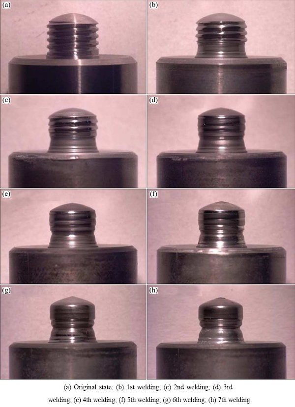
Fig. 3 Appearance of threaded tool after each FSW experiment [9]
Figure 3 shows the appearance of the threaded tool after each FSW experiment. It can be seen that the threads near the pin root almost disappear after the first welding (see Fig. 3(b)). The maximum diameter, i.e., minimum wear, occurs in the upper half-part of the pin, while the minimum pin diameter, i.e., maximum wear, exists in the lower half-part near the shoulder (see Figs. 3(b)-(h)). After the sixth welding is performed, all the original threads of the pin have been completely worn away (see Figs. 3(g) and (h)).
As shown in Fig. 4, the variations in shoulder size and pin length increase with increase in travel distance, but the variation is marginal. For example, when the seventh welding is completed, the shoulder diameter, shoulder height and pin length are merely changed by 2.2%, 2.5% and 1.2%, respectively. This implies that the shoulder wear and the pin longitudinal wear are very small.
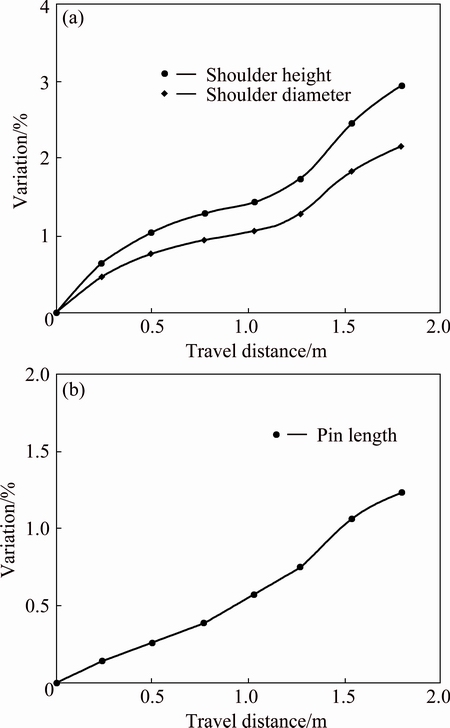
Fig. 4 Variations in shoulder size (a), and pin length (b) [9]
The variations in pin diameter are very remarkable, as shown in Fig. 5. The pin diameter significantly decreases with increase in travel distance, especially when the welding speed is relatively low. For example, after an initial welding is performed at a welding speed of 25 mm/min, the pin diameter almost decreases by 11%. After the seventh welding is performed, 27% of the pin diameter at the maximum-wear location has disappeared (see Fig. 5(a)). This indicates that the radial wear of the pin is appreciable and is related to the welding process parameters. It should be pointed out that the variations in pin diameter are not the same for different locations of the pin although they all increase with the increase in travel distance. With respect to the three typical locations of 0.6, 1.5 and 3.2 mm from the pin root, the moderate, high and low variations, respectively take place in the pin diameter (see Fig. 5(b)). This indicates that the radial wear of the pin is uneven at different locations of the pin.
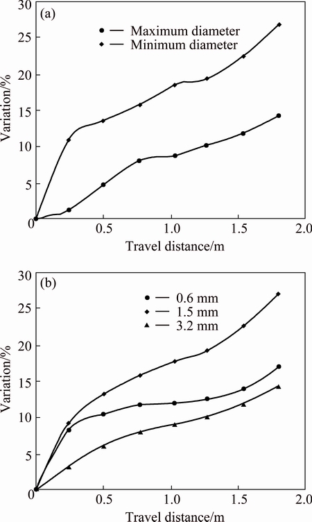
Fig. 5 Variations in pin diameter at extreme-wear locations (a), and typical locations (b) [9]
PRATER [35] studied the volumetric wear of the tool to the process parameters, i.e., rotation speed (��), traverse speed (��) and distance welded (l). Though the studies utilized different AMCs and tool geometries, there were some trends that seemed to hold in general for FSW of AMCs. An obvious direct proportionality between wear and linear weld distance was reported in all the studies.
FERNANDEZ and MURR [40] estimated the tool wear for welds of Al359+20%SiCp material based upon the careful selection of process parameters. To isolate the effect of rotation speed on wear, welds were performed at a fixed traverse rate while varying the spindle speed from 500 r/min to 1000 r/min. It was found that the percent tool wear increased with increase in rotation speed. This trend was also observed by PRADO et al [44] who found that wear increased with rotation speed up to 2000 r/min. To characterize the dependence of wear on traverse speed, FERNANDEZ and MURR [40] expanded the experimental matrix to include variations in traverse speeds. The wear curves for the seven combinations of traverse and rotation speeds were plotted. By comparing wear data for parameter sets with the same rotation speed but different traverse speeds, it was apparent that wear decreases with increasing traverse speed. Though the inverse relationship between wear and traverse speed is non-intuitive, it provides experimental evidence that tool wear in the FSW process was a shear, rather than drag, phenomenon. Figure 6 shows a summary of effective wear versus weld traverse distance data and also included the previous experimental data from SHINDO et al [45]. Figure 6 suggests that for extensive (or extended) FSW of aluminum alloy 359+20%SiC AMC, the optimum weld parameters approached to a tool rotational speed of 500 r/min and traverse speed of 11 mm/s. For these optimum conditions, the tool wear will not exceed 10%.
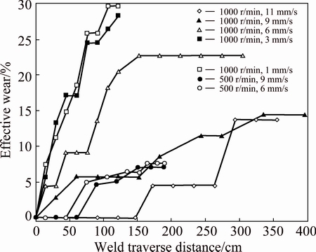
Fig. 6 Pin tool wear with respect to weld traverse distance [40]
PRADO et al [44] investigated the tool wear behavior in FSW of Al6061 + Al2O3 composite. For O1 tool-steel threaded pin, heat-treated to a Rc hardness of 62, at a tool rotation speed of 500-2000 r/min and a traverse speed of 60 mm/min, no apparent tool wear was noted for FSW of Al6061, severe tool wear occurred for FSW of Al6061 + Al2O3 composite. The wear rate of the tool increased linearly with increasing linear welding distance. The largest wear rate was observed at a tool rotation speed of 1000 r/min. This means that the wear rate of tool did not increase when the tool rotation speed was increased above 1000 r/min. A possible reason for this is the improvement of flow properties of the composite at high tool rotation rate due to increased thermal input.
A simple comparison of these pin images, shown in Fig. 7, readily illustrates the degree and character of tool wear for FSW in the AMC. It shows no apparent tool wear for the FSW in Al6061. The images in Figs. 7(a) and (b) show a recognizable difference between FSW regimes corresponding to 500 and 1000 r/min with greater wear in the 1000 r/min regime. Figure 8(a) shows a more quantitative representation of tool wear for the four experimental FSW rotation speeds, with no apparent wear for the FSW in the commercial 6061 Al alloy in contrast to the corresponding rotation speed (1000 r/min) in the AMC. The AMC data in Fig. 8(a) fit reasonably well to straight line plots and from these slopes the effective wear rates are plotted as a function of the tool rotation speed as shown in Fig. 8(b). It can be observed in Fig. 8(b) that the wear rate is maximum for 1000 r/min and then decreases irregularly for 1500 and 2000 r/min, possibly as a consequence of the increased fluid like behavior and turbulent particle flow at tool rotation speeds above 1000 r/min. For corresponding, linear FSW for the 6061 aluminum alloy, there was no apparent tool wear rate.
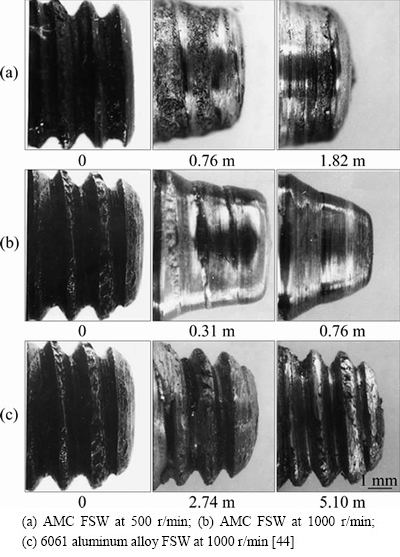
Fig. 7 Tool (pin) sequences showing FSW wear features
2.2.2 Tool geometry and tool material
PRADO et al [15] and SHINDO et al [45] found that the tool wear in the FSW process of Al6061 + Al2O3 and Al359 + SiC composites produced a self-optimized shape which results in excellent welds and no additional tool wear when that is achieved. This provides a new idea for the geometry design of the welding tool.
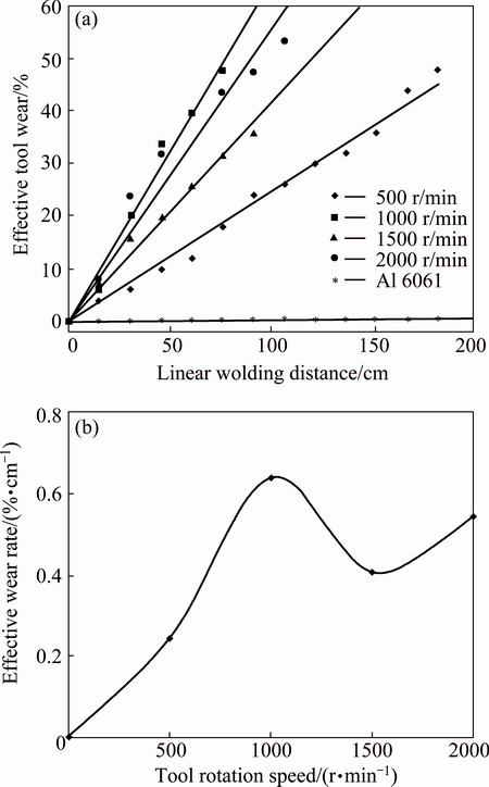
Fig. 8 Pin wear with respect to FSW linear traverse (a) and pin wear rate with respect to tool rotation speed (b) [44]
SHINDO et al [45] proposed that the FSW of Al359 + 20%SiC AMC using threaded steel pin tools for welding produced a self-optimized shape with no threads which continue to produce excellent, homogeneous welds, but without additional tool wear or shape change at fixed welding speeds above 6 mm/s. This self- optimized shape was slightly different at 6 and 9 mm/s. Extrapolations of linear wear rate data indicated zero wear rate above about 11 mm/s weld speed. Figure 9 illustrates some typical tool/pin wear sequences at different weld speeds. These photographs were used to measure tool wear, which is given as a percent of mass change in comparison to original tool in Fig. 9. The measured effective wear percent was plotted versus traverse or weld distance with weld speeds of 1, 3, 6, and 9 mm/s at 1000 r/min rotation speed as shown in Fig. 10. It can be noted from Fig. 10 that the initial slopes of the wear curves decreased with the increase in weld speed. Taken together with the tool wear or tool image sequences in Fig. 9, Fig. 10 suggested that the same tool shapes/wear shapes emerged at low speeds as those at the higher speeds if the tool are used for longer durations or if it traversed correspondingly more material.
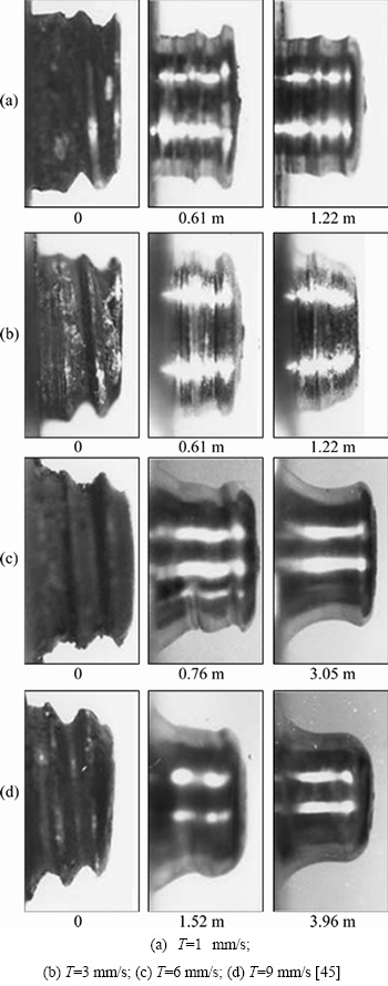
Fig. 9 Tool (pin) sequences showing AMC-FSW wear features for constant tool rotation of 1000 r/min and weld traverse distances noted for specific weld speeds
However, very high initial wear rates may remove enough tool volume to make an optimized shape unattainable. The initial wear rates represented by a straight-line fit to the corresponding curves in Fig. 10, between zero and 100 cm traverse, are shown in Fig. 11 in comparison with the same data for Al6061+ 20%Al2O3 particles from the work of PRADO et al [15].
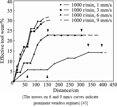
Fig. 10 Pin tool wear with respect to different distances at different speeds
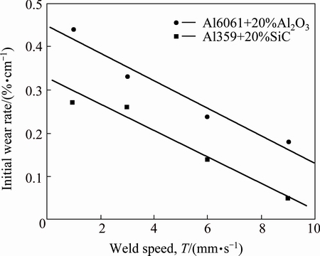
Fig. 11 Comparison for wear rates for Al 359+20%SiC and Al 6061+20%Al2O3 [45]
It can be seen in Fig. 11 that the wear rates for Al359+20%SiC are shifted downward in contrast to the wear rate for Al6061+20%Al2O3, while the slopes are identical. The fact that the tool length for the Al359+ 20%SiC work piece was about 30% shorter than that for the Al6061+20%Al2O3 had also contributed to the wear data shift shown in Fig. 11. Extrapolating the data for Al359+20%SiC indicated zero wear rate above about 11 mm/s traverse speed. It is also worth noting that the tool in both the wear conditions depicted in Fig. 11 is subjected to a transient period or a thermal cycle between the 15 cm plate sections. This produced a more severe wear condition than that achieved by continuous section welding. An investigation done by PRADO et al [15] provided a preliminary assessment of the wear of cylindrical threaded tools in the butt welding of Al6061+ 20%Al2O3 particles. It was observed that tool wear and the rate of wear for hardened, steel, right-hand screws rotating at 1000 r/min in the FSW of Al6061+ 20%Al2O3 particles were observed to decrease for increasing weld or traverse speeds. When sufficiently long traverse distances were reached, tool wear becomes small or negligible, and an optimized tool shape emerged. This shape was slightly different at 6 and 9 mm/s weld speeds but in each case a self-optimized tool shape emerged. This self-optimizing wear phenomena and tool shape resulted by counter motions of solid-state flow regimes which depend upon both tool rotation speed and actual weld traverse speed. Although sound, porosity-free welds were obtained with both the unworn, threaded pin tool and the worn, unthreaded pin tool, microstructures varied and the worn pin tool produced a narrower heat affected zone with lesser drop in hardness than the threaded pin tool.
PALANIVEL et al [24] considered the four FSW parameters, i.e., tool pin profile, tool rotational speed, welding speed and axial force. Tools made of high carbon high chromium steel (HCHCr) with different tool profiles, i.e., straight square, tapered square, straight hexagon, straight octagon and tapered octagon were used for FSW of dissimilar AA5083H111-AA6351 T6 aluminum alloy. Analysis of variance (ANOVA) technique was used to check the adequacy of the developed model. The experiment results showed that wear resistance increased as tool rotational speed increases and reaches to maximum at 950 r/min. Further increase in tool rotational speed leads to decrease in wear resistance. Increase in frictional heat generation was observed with increase in tool rotational speed. Lower and higher heat input condition prevail at lower (600 and 775 r/min) and higher (1125 and 1400 r/min) tool rotational speeds. Similarly, increase in welding speed leads to increase in wear resistance which reaches maximum at 63 mm/min. Further increase in welding speed leads to decrease in the wear resistance. The wear resistance increases as axial force increases and reaches maximum at 1.25 t. Further increase in axial force leads to decreased wear resistance. Low heat is generated at low axial forces (1 and 1.25 t) which also causes improper consolidation of material which further leads to poor wear resistance. At higher axial forces (1.75 and 2 t), higher heat is generated with higher plunge depth of the tool into the welded plate is higher and flash level which causes local thinning of welded plate leading to poor wear resistance. Tool pin profile plays a crucial role in material flow during welding. The relationship between the static and dynamic volumes of the tool pin decided the path for the flow of plasticized material from the leading edge to the trailing edge of the rotating tool. The square pin profile, hexagon pin profile and octagon pin profile produced 63, 95, 126 pulses/s respectively at the rotational speed of 950 r/min. There was negligible pulsating action in the octagonal and hexagonal pin profiled tool because it almost resembles a straight cylindrical pin profiled tool at high rotational speed. The tapered pin profile tools are ineffective to produce pulsating stirring action. Hence, the joints welded using straight pin profiles yield highest wear resistance. After analyzing the response surfaces and contour plots, the maximum achievable wear resistance value is found to be 244.693 m/mm3. The corresponding FSW parameters for maximum value are tool pin profile of straight square tool, tool rotational speed of 950 r/min, welding speed of 63 mm/min and axial force of 1.5 t.
PRATER et al [41] used a Taguchi L27 orthogonal array for the characterization of tool wear for various process parameters in the FSW of the AMC Al359+ 20%SiCp. The tool geometry selected was the Trivex, an approximately triangular probe shape which arose from the CFD modeling done by SHERCLIFF and COLEGROVE [46]. It was found by SHERCLIFF and COLEGROVE [46] that the shape was effective in reducing traversing forces by 18% to 25% and the axial force by about 12%. The surface of the probe was convex and the three vertices formed an equilateral triangle. Each vertex was located at the center of a circle which contains the other two vertices. The steel Trivex tools used in the study had a swept diameter of 0.635 cm, a probe length of 0.47 cm and the shoulder diameter of 1.91 cm. Samples were welded at one degree angle of tilt with a plunge depth of 0.023 cm. Three factors (rotation speed, traverse speed, and length of weld) were correlated with percent tool wear. The multiple regression model (W=0.584l-1.038v-0.009��-6.028 with a R2 value of 0.81) indicated that wear is strongly dependent on process parameters. This relationship is in the form of W����l/v, where percent total tool wear (W) is inversely proportional to traverse speed (��) and directly proportional to rotation speed (��) (r/min) and length of weld (l). SINCLAIR et al [47] investigated the effect of preheating on process forces of FSW. The weld samples were plates of A6061-T6 aluminum, nominally 0.635 cm in thickness, 7.62 cm in width, and 22.83 cm in length. The FSW tool was made from H-13 tool steel heat treated to RC 48-50. It had 1.58 cm-diameter shoulder and a 0.635 cm side-length Trivex pin ground down to be 0.60 cm in length. The tool was at 1�� tilt angle and 0.019 cm plunge depth to achieve 80% shoulder contact; all the geometry combined to give a joint ligament of just under 0.0254 cm. Overall, the heating of the aluminum with an additional source beyond the FSW tool definitely reduced the major force associated with the welding process. With even small amount of heating, the average axial force of welding AA6061 at some temperature dropped by a minimum of 21% for all welding traverse speeds. The maximum reduction in force was 43%. The reduced force can lead to the increase in the allowable traverse speed.
MAHMOOD et al [42] joined the aluminum matrix composites reinforced with both SiC and graphite particles using a FSW process. The wear characteristics of the welded joints were investigated at a constant load of 50 N and a rotational speed of 1000 r/min using a pin-on-disk wear testing apparatus. The focus was on the influences of the FSW processing parameters (tool geometry, rotational speed, and welding speed) on the wear characteristics of the welded joint of the considered hybrid aluminum matrix composite under dry sliding conditions. The wear resistances of the friction stir welded composite joints were examined using three different tool profiles (square, hexagonal, and octagonal). For every tool profile, the wear tests were conducted at four different welding speeds (35, 45, 55, and 65 mm/min) and at different rotational speeds of 630, 800, 1000, and 1250 r/min. Figure 12 shows the variation of the wear rate with welding speed for various tool pin profiles when the rotational speed was maintained at the constant values of 630 and 1250 r/min. The horizontal line shown in Fig. 12(a) was drawn only for the purpose of comparison between the as-cast base AMCs and the welded zone. The line represented the nominal value of the wear rate at the base AMCs measured at various points. The results demonstrated that the tool geometry had significant influence on the wear resistance of the welded joint. In all considered cases, the welded joints produced by the square pin profile tool exhibited superior wear resistance compared to those joints welded by octagonal pin profile tools.
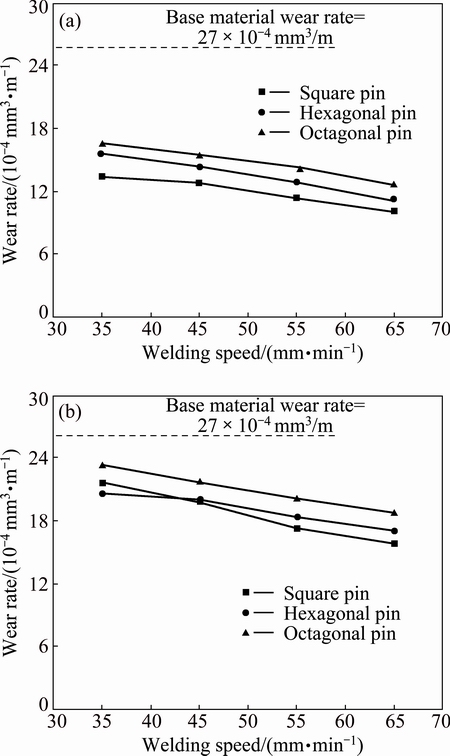
Fig. 12 Variation of wear rate with respect to welding speeds for different pin profiles at rotational speed of 630 r/min (a) and 1250 r/min (b) [42]
The wear rates were measured at different rotational speeds of 630, 800, 1000, and 1250 r/min, and at different constant welding (transverse) speeds of 35, 45, 55, 65 mm/min. The results, shown in Fig. 13(a), indicated that the wear rate increased with the increase in the rotational speed, for all the examined welding speeds. The joint welded at 630 r/min and 65 mm/min experienced the highest wear resistance among the other examined specimens. A set of experiments were conducted to measure the wear rate at different welding speeds (35, 45, 55, and 65 mm/min), while keeping the rotational speed at the constant values of 630, 800, 100, and 1250 r/min. It can be seen from Fig. 13(b) that the maximum wear rate of the welding zone was achieved at welding (traverse) speed of 45 mm/min and a rotational speed of 1250 r/min.
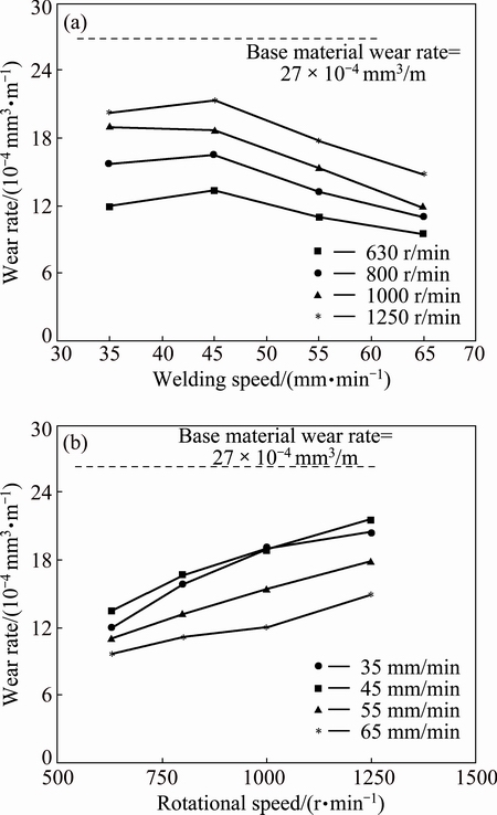
Fig. 13 Variation of wear rate with respect to welding speed at different rotational speeds (a) and with respect to rotational speed at different welding speeds (b) for FSW AMCs welded joints [42]
The wear rate increased by 6% with increase of the transverse speed from 35 mm/min to 45 mm/min, respectively. When the transverse speed was raised from 45 mm/min to 65 mm/min, the wear rate decreased drastically. The specimens welded using 630 r/min and 65 mm/min had the lowest wear rate. Accordingly, it can be said that the wear rate decreased with the increase in welding speed at constant rotational speed, and it increased with the increase in rotational speed at constant welding speed.
PRATER et al [48] developed a dimensionless parameter that was used to estimate the amount of volumetric wear for welding a AMC. The study derived a dimensionless number based on three major process variables in FSW, i.e., rotation speed, traverse speed, and length of weld. The number was correlated with wear data collected experimentally using a steel FSW tool to join Al359+20%SiCp. The use of the dimensionless number as a classifier for tool condition was also evaluated. PRATER et al [36] evaluated the effectiveness of harder tool materials to combat wear in the FSW of AMCs. The tool materials considered were O1 steel, cemented carbide (WC-Co) of the micrograin and submicrograin varieties, and WC-Co coated with diamond for two AMCs, i.e., Al359 (T6 temper) with 20% SiC (by volume), and Al359 containing 30% SiC. The challenges which accompanied the application of harder tool materials and diamond coatings in FSW were also discussed by WEINERT and KONIG [49] and COELHO et al [50]. The SiC reinforced composite study presented the very first use of diamond-coated tools in FSW and the first comparative evaluation of tool materials.
The wear resistance of tools in FSW of AMCs is subjected to a law of diminishing returns. Increasing the hardness ratio from 0.31 (the value associated with O1 tool steel) to 0.77 (cemented WC-Co) produced a very substantial decrease in wear of the probe (somewhere in the 60%-80% range, depending on reinforcement level). Increasing the hardness ratio from 0.77 to 2.69 by applying a diamond coating produced a comparatively lower proportional decrease in wear. The measured, cumulative wear of each probe for the tool materials and reinforcement percentages are shown in Fig. 14.
The highest wear values were associated with the O1 steel tools. The wear resistances of WC-Co micrograin and WC-Co submicrograin were clearly superior to those of steels at both 20% and 30% reinforcement levels. For instance, the wear experienced by the WC-Co micrograin tool at 30% is nine times less than that observed for the O1 steel tool under the same conditions. Overall, the most wear-resistant tool material is WC-Co coated with diamond. An important finding of the study was that there is no linear relationship between wear and percentage reinforcement. To illustrate this point, close-up images of probe profiles prior to welding and after completing the series of Al AMC welds with either 20% or 30% reinforcement were compared. These images for the steel, WC-Co micrograin, WC-Co submicrograin, and diamond-coated inserts, respectively are shown in Fig. 15. The difference in wear with percentage reinforcement for WC-Co and the diamond-coated specimens is very subtle. Wear (and the increase in wear with percentage reinforcement) was much more dramatic for the O1 steel inserts.
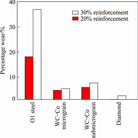
Fig. 14 Percentage wear with respect to tool material [36]
WANG et al [51] used three different types of tool materials for investigating the tool wear mechanism and interactions between the tools and Ti-6Al-4V alloy. Three tools were made of W-1.1%La2O3 and two different grades of WC-Co-based materials, i.e., WC-Co material as a sintered rod with the grade of CY16 (nominal composition of 73% WC, 8% Co, 8% TiC and 11% TaC), while the other was in the form of powder with the grade of WC411 (nominal composition of 89% WC and 11% Co). For convenience, the three tool materials were referred to as W-La, CY16 and WC411 correspondingly. FSW trials were performed on Ti-6Al-4V sheets with a thickness of 2.5 mm. A length of 7.62 cm was selected for each FSW run using one of the three tool materials. The first six runs included a combination of tool rotation at a rate of 900, 1000 and 1100 r/min, and traverse speeds of 25 and 50 mm/min. For characterization of tool wear, a photographic technique and mass loss measurement were used.
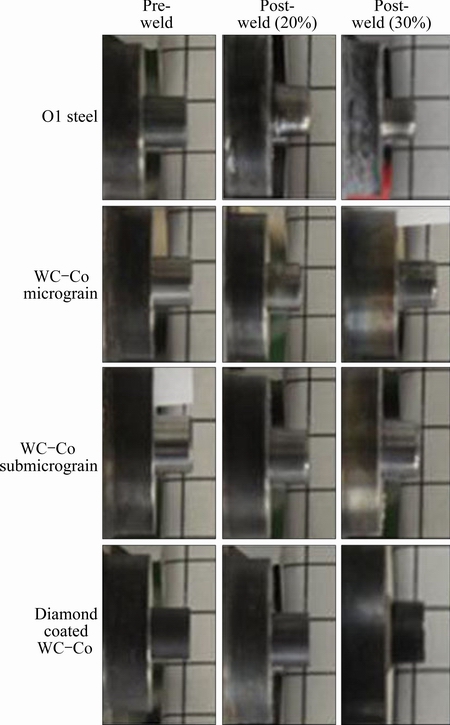
Fig. 15 Comparison of characteristic tool profiles for 20% and 30% SiC reinforced composite [36]
Figure 16 presents the appearance of three tools after different welding lengths. Changes in tool configurations were observed in the CY16 and W-La tools after the first trial, while no noticeable change was observed in the WC411 tool after the entire set of six runs. The CY16 and W-La tools experienced different degradation patterns during FSW. The CY16 tool suffered fracture at both pin and shoulder parts without plastic deformation. The pin length was almost constant after FSW. On the other hand, such fracture failures were not observed in the W-La tool, which experienced mushroom-type plastic deformation at both pin and shoulder parts. Since the CY16 tool experienced severe fracture failure, so it was excluded from further tool wear analysis. A large pin was used for reducing the plastic deformation in W-La tool pin which was a function of the FSW stress and temperature. Therefore, a new tool of a cylindrical pin with an increased pin tip diameter of 6.3 mm was used for the additional evaluation and comparison. To distinguish it from the earlier W-La tool with the small conical pin, the new tool was named as W-La-L, where L denotes ��large pin��. Appearances of the tools after certain welding lengths are shown in Fig. 17. Although mushroom type of deformation was observed in the W-La-L tool also, it experienced much less plastic deformation as compared to the W-La tool. It should be mentioned that for the W-La-L tool, the first two runs were 7.62 cm in length, each under the rotation rate of 1000 r/min and traverse speed of 25 and 50 mm/min in succession, which is the same as in the first two FSW runs with the W-La tool. For both W�CLa and W�CLa-L tools, after the first trial, the tool pin geometry and shape remained almost constant. The tool pin itself undergoes deformation to produce geometries and shape that reduce the net stress. After these trials, a 27.94 cm long weld run was carried out at 1000 r/min and 25mm/min.
Figure 18 shows the mass change corresponding to the weld length for the three tools, i.e., W-La, W-La-L and WC411. Mass loss was the lowest and almost in a linear relationship to welding length for the WC411 tool. For both W-La and W-La-L tools, mass loss with FSW lengths does not have a linear relationship. The mass loss of lanthanated tungsten tools was larger as compared to the WC411 tool. Except for the first trial, less mass loss per unit weld length was observed in the W�CLa-L tool as compared to the W�CLa tool. For lanthanated tungsten tools, large-sized pin design was preferred to reduce the tool wear.
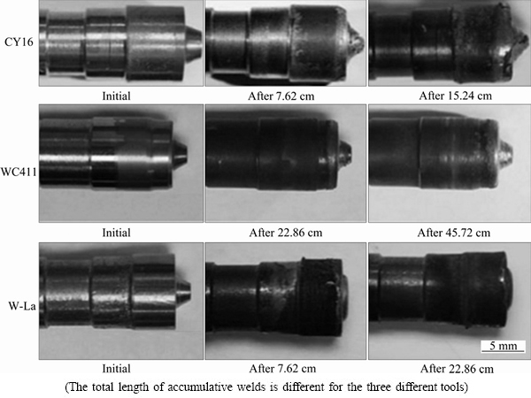
Fig. 16 Appearance of tools after different welding lengths [51]
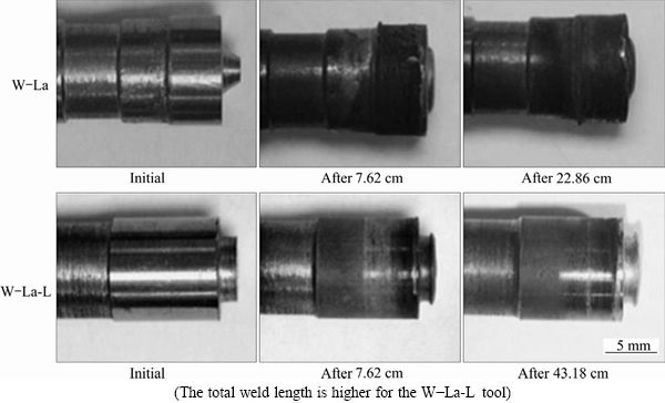
Fig. 17 Changes in tool profiles with increased weld length for different tools [51]
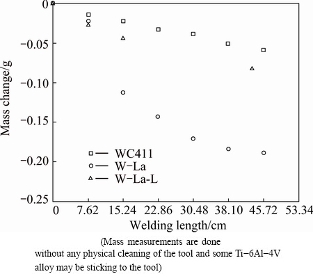
Fig. 18 Mass change versus total welding length for WC411, W-La and W-La-L tools [51]
3 Conclusions
1) FSW is the most preferred joining method used in AMCs. FSW is done below the melting point of the workpiece preventing the formation of theta phase which produces the stronger joints as compared to any of the fusion welding process.
2) FSW of AMCs is complicated by rapid and severe wear of the tool which results due to the contact between the tool and the much harder reinforcement particles. The amount of wear incurred by the tool depends upon number of factors, i.e., rotational speed, transverse speed, axial force, tool geometry, the hardness of the tool relative to the reinforcement material in the composite and the composite��s percent reinforcement.
3) Quantification of tool wear is done by capturing the close-up images of the tool after a given weld traverse distance and comparing them with the pre-weld images. The tool wear is also calculated by measuring the mass of the tool before and after the welding of the specimens.
4) The wear rate of the tool increases with increase in welding distance and tool rotation. The increase in wear rate with tool rotation was up to a certain limit of revolution. Thereafter, increase in tool rotation decreased the wear rate of the tool. At high tool rotation, there was improvement of flow properties of the composite due to increased thermal input which reduced the tool wear. It was also seen that there was inverse relation between the wear and transverse speed which suggested that the tool wear in FSW was a shear rather than a drag phenomenon. The wear resistance increased with increase in axial force up to a certain limit. Thereafter, the increase in axial force decreased the wear resistance of the tool.
5) It is found that the wear also depends upon the tool profile and material. Increasing the hardness ratio of the tool material from 0.31 to 0.77 decreases the wear rate by about 60%-80%.
6) The development of wear-resistant tools is necessary to make solid-state joining of AMCs cost effective by eliminating the expenses associated with consumable tooling. The ultimate goal of research into FSW of AMCs is to produce repeatable, robust welds while simultaneously minimizing the tool replacement. Effect on tool wear due to temperature variation is the need of the hour.
Acknowledgement
The authors would like to thank the anonymous reviewers for their valuable comments that have contributed a lot in raising the standard of the manuscript.
References
[1] GONI J, EGIZABAL P, COLETO J, MITXELENA I, LEUNDA I, GURIDI J R. High performance automotive and railway components made from novel competitive aluminum composites [J]. Mater Sci Technol, 2003, 19: 930-934.
[2] URENA A, ESCALERA M D, GIL L. Influence of interface reactions on fracture mechanisms in TIG arc-welded aluminum matrix composites [J]. Compos Sci Technol, 2000, 60: 613-622.
[3] WANG H M, CHEN Y L, YU L G. In-situ weld-alloying/laser beam welding of SiCp/6061Al MMC [J]. Mater Sci Eng A, 2000, 293: 1-6.
[4] HUANG R Y, CHEN S C, HUANG J C. Electron and laser beam welding of high strain rate superplastic Al-6061/SiC composites [J]. Metall Mater Trans A, 2001, 32: 2575-2584.
[5] ZHANG X P, QUAN G F, WEI W. Preliminary investigation on joining performance of SiCp-reinforced aluminum metal matrix composite (Al/SiCp�CMMC) by vacuum brazing [J]. Composites Part A, 1999, 30: 823-827.
[6] ASKEW J R, WILDE J F, KHAN T I. Transient liquid phase bonding of 2124 aluminum metal matrix composite [J]. Mater Sci Technol, 1998, 14: 920-924.
[7] ZHANG X P, YE L, MAI Y W, QUAN G F, WEI W. Investigation on diffusion bonding characteristics of SiC particulate reinforced aluminum metal matrix composites (Al/SiCp�CMMC) [J]. Composites, Part A, 1999, 30: 1415-1421.
[8] URENA A, SALAZAR J M G, ESCALERA M D, HANSON W B. Diffusion bonding of alumina reinforced 6061 alloy metal matrix composites using Al-Li interlayer [J]. Mater Sci Technol, 2000, 16: 103-109.
[9] LIU F J, FENG J C, FUJII H, NOGI K. Wear characteristics of a WC-Co tool in friction stir welding of AC4A+30% vol. SiCp composite [J]. International Journal of Machine Tools and Manufacture, 2005, 45: 1635-1639.
[10] MOHANTY H K, MAHAPATRA M M, KUMAR P, BISWAS P, MANDAL N R. Effect of tool shoulder and pin probe profiles on friction stirred aluminum welds��A comparative study [J]. Journal of Marine Science Application, 2012, 11: 200-207.
[11] THOMAS W M, NICHOLAS E D, NEEDHAM J C, MURCH M G, TEMPLESMITH P, DAWES C J. Friction stir butt welding: G. B. Patent, 9125978.8 [P]. 1991-12-06.
[12] MEILINGER A, TOROK I. The importance of friction stir welding tool [J]. Journal of Production Processes and Systems, 2013, 6: 25-34.
[13] MISHRA S R, MAHONEY W M. Friction stir welding and processing [M]. Material Park, Ohio: The Materials Information Society, 2007: 6-19.
[14] MISHRA R S, MA Z Y. Friction stir welding and processing [J]. Materials Science and Engineering R: Reports, 2005, 50: 1-78.
[15] PRADO R A, MURR L E, SOTO K F, MCCLURE J C. Self-optimization in tool wear for friction-stir welding of Al 6061+20%Al2O3 [J]. Materials Science and Engineering A, 2003, 349: 156-165.
[16] CHEN Y C, FENG J C, LIU H J. Stability of the grain structure in 2219-O aluminum alloy friction stir welds during solution treatment [J]. Mater Charact, 2007, 58: 174-178.
[17] XIE G M, MA Z Y, GENG L. Effect of microstructural evolution on mechanical properties of friction stir welded ZK60 alloy [J]. Mater Sci Eng A, 2008, 486: 49-55.
[18] LIU H J, FUJII H, MAEDA M, NOGI K. Tensile properties and fracture locations of friction stir welded joints of 6061-T6 aluminum alloy [J]. J Mater Sci Lett, 2003, 22: 1061-1063.
[19] LEE W B, YEON Y M, JUNG S B. Evaluation of the microstructure and mechanical properties of friction stir welded 6005 aluminum alloy [J]. Mater Sci Technol, 2003, 19: 1513-1518.
[20] BOOTH D P P, STARINK M J, SINCLAIR I. Analysis of local microstructure and hardness of 13 mm gauge 2024-T351 AA friction stir welds [J]. Mater Sci Technol, 2007, 23: 276-284.
[21] NASA. Friction stir welding, space shuttle technology summary [EB/OL][2001]. http://www.nasa.gov/centers/marshall/pdf/104835- mainfriction.pdf.
[22] PERIYASAMY P, MOHAN B, BALASUBRAMANIAN V, RAJAKUMAR S, VENUGOPAL S. Multi-objective optimization of friction stir welding parameters using desirability approach to join Al/SiCp metal matrix composites [J]. Transactions of Nonferrous Metals Society of China, 2013, 23(3): 942-955.
[23] MOHAMADREZA N, ABBAS M S, SIPRO Y. Taguchi optimization of process parameters in friction stir welding of 6061 aluminum alloy: A review and case study [J]. Scientific Research, 2011, 3: 144-155.
[24] PALANIVEL R, MATHEWS P K, MURUGAN N, DINAHARAN I. Prediction and optimization of wear resistance of friction stir welded dissimilar aluminum alloy [J]. Procedia Engineering, 2012, 38: 578-584.
[25] JAYARAMAN M, SIVASUBRAMANIAN R, BALASUBRAMANIAN V, LAKSHMINARAYANAN A K. Optimization of process parameters for friction stir welding of cast aluminum alloy A319 by Taguchi method [J]. Journal of Scientific & Industrial Research, 2009, 68: 36-43.
[26] ZHANG Z, LIU Y L, CHEN J T. Effect of shoulder size on the temperature rise and the material deformation in friction stir welding [J]. International Journal of Advanced Manufacturing Technology, 2009, 45: 889-895.
[27] GHARACHEH ABBASI M, KOKABI H A, DANESHI H G, SHALCHI B, SARRAFI R. The influence of the ratio of rotational speed/traverse speed on mechanical properties of AZ31 friction stir welds [J]. International Journal of Machine Tools & Manufacture, 2006, 46: 1983-1987.
[28] KUNZE J M, BAMPTOM C C. Challenges to developing and producing MMCs for space applications [J]. Journal of the Minerals, Metals and Material Society, 2001, 53: 22-25.
[29] STORJOHANN D, BARABASH O M, DAVID S A, SKLAD P S, BLOOM E E, BABU S S. Fusion and friction stir welding of aluminum metal matrix composites [J]. Metallurgical and Materials Transactions A, 2005, 36: 3237-3247.
[30] ELLIS M B D, GITTOS M F, THREADGILL P L. Joining aluminum based metal matrix composites [J]. Materials World, 1994, 8: 415-417.
[31] ISEKI T, KAMEDA T, MARUYAMA T. Interfacial reactions between SiC and aluminium during joining [J]. Journal of Materials Science, 1984, 19: 1692-1698.
[32] DAHOTRE N B, MCCAY M H, MCCAY T D, GOPINATHAN S, ALLARD L F. Pulse Laser processing of a SiC/Al-alloy metal matrix composite [J]. Journal of Material Research, 1991, 6: 514-529.
[33] KALAISELVAN K, MURUGAN N. Role of friction stir welding parameters on tensile strength of AA6061-B4C composite joints [J]. Transactions of Nonferrous Metals Society of China, 2013, 23(2): 616-624.
[34] BISWAS P, MANDAL R N. Experimental study on friction stir welding of marine grade aluminum alloy [J]. Journal of Ship Production, 2009, 25: 1-6.
[35] PRATER T. Solid-state joining of metal matrix composites: A survey of challenges and potential solutions [J]. Materials and Manufacturing Processes, 2011, 26: 636-648.
[36] PRATER T, STRAUSS ALVIN M, COOK GEORGE E, GIBSON BRIAN T, COX CHASE D. A comparative evaluation of the wear resistance of various tool materials in friction stir welding of metal matrix composites [J]. Journal of Materials Engineering and Performance, 2013, 22: 1807-1813.
[37] PRATER T, COOK G E, STRAUSS A M, DAVIDSON J, HOWELL M. Parameterization of friction stir welding of Al 6061/SiC/17.5p for various tool materials [C]//Proc. 8th International Conference on Trends in Welding Research. Pine Mountain, GA, 2008: 102-107.
[38] COLLIER M, STEEL R, NELSON T, SORENSEN C, PACKER S. Grade development of polycrystalline cubic boron nitride for friction stir processing of ferrous alloys [J]. Materials Science Forum, 2003, 426-432: 3011-3016.
[39] MA Z Y, XIAO B L, WANG D. Challenge and opportunities for friction stir welding of discontinuously reinforced metal matrix composites [C]//Proc The 18th International Conference on Composite Materials. ICC Jeju, Korea, 2011: 21-26.
[40] FERNANDEZ G J, MURR L E. Characterization of tool wear and weld optimization in the friction-stir welding of cast aluminum 359+20% SiC metal matrix composite [J]. Materials Characterization, 2004, 52: 65-75.
[41] PRATER T J, STRAUSS A M, COOK G E, MACHEMEHL C, SUTTON P, COX C D. Statistical modeling and prediction of wear in friction stir welding of a metal matrix composite (Al 350/SiC/20p) [J]. Journal of Manufacturing Technology Research, 2010, 2: 1-13.
[42] MAHMOOD H A, MOHAMMED A, TAREK Q, AHMED G. Effect of processing parameters on friction stir welded aluminum matrix composites wear behavior [J]. Materials and Manufacturing Processes, 2012, 27: 1419-1423.
[43] PRATER T J, STRAUSS A M, COOK G E, GIBSON B T, COX C D. A phenomenological model for tool wear in friction stir welding of metal matrix composites [J]. Journal of Metallurgical and Materials Transactions A, 2013, 44: 3757-3764.
[44] PRADO R A, MURR L E, SHINDO D J, SOTO K F. Tool wear in the friction-stir welding of aluminum alloy 6061+Al2O3: A preliminary study [J]. Scripta Materialia, 2001, 45: 75-80.
[45] SHINDO D J, RIVERA A R, MURR L E. Shape optimization for tool wear in the friction-stir welding of cast Al359-20% SiC MMC [J]. Journal of Materials Science, 2002, 37: 4999-5005.
[46] SHERCLIFF H R, COLEGROVE A P. Development of Trivex friction stir welding tool, part 2: Three-dimensional flow modeling [J]. Science and Technology of Welding and Joining, 2006, 9: 352-361.
[47] SINCLAIR PAUL C, LONGHURST WILLIAM R, CHASE COX D, LAMMLEIN DAVID H, STRAUSS ALVIN M, COOK GEORGE E. Heated friction stir welding: an experimental and theoretical investigation into how preheating influences on process forces [J]. Materials and Manufacturing Processes, 2010, 25: 1283-1291.
[48] PRATER T, COX C, GIBSON B, STRAUSS ALVIN M, COOK GEORGE E. Dimensional analysis and a potential classification algorithm for tool wear in friction stir welding of metal matrix composites [J]. Proceedings of the Institution of Mechanical Engineers, Part C: Journal of Mechanical Engineering Science, 2012, 226: 2759-2769.
[49] WEINERT K, KONIG W. A consideration of tool wear mechanism when machining Metal Matrix Composite (MMC) [J]. CIRP Ann Manuf Technol, 1993, 42: 95-98.
[50] COELHO R T, YAMADA S, ASPINWALT D K, WISE M L H. The application of polycrystalline Diamond (PCD) tool materials when drilling and reaming aluminum based alloys including MMC [J]. Int J Mach Tools Manuf, 1995, 35: 761-774.
[51] WANG J, SU J, MISHRA R S, XU R, BAUMANN J A. Tool wear mechanisms in friction stir welding of Ti-6Al-4V alloy [J]. Wear, 2014, 321: 25-32.
Ashish BIST1, J. S. SAINI2, Bikramjit SHARMA2
1. Mechanical Engineering Department, Graphic Era University, Dehradun 248002, Uttarakhand, India;
2. Mechanical Engineering Department, Thapar University, Patiala 147004, Punjab, India
ժ Ҫ������Ħ�������������ϲ�����ѡ�ĺ��ӷ���������һ�ֹ�̬���ӷ��������Է�ֹ�ۺ����γɵĽ����仯���ﵼ����ѧ�����½�������Ħ��������Ҫ�������ǽ������ĥ��ĥ�������ڽ������븴�ϲ�����Ӳ����ǿ��ڽӴ�����ɵġ����������˲�ͬ����Ħ���������Խ�����ĥ���Ӱ�졣�о����֣�������IJ���ĥ������������ת�ٺͺ��ӳ��ȳ����ȣ����н��ٶȳʷ��ȡ�������ļ�����״Ҳ��ĥ����������ء���������������ת������Ż���״�Լ�Сĥ��
�ؼ��ʣ�����Ħ�������������ϲ��ϣ�����ĥ��
(Edited by Yun-bin HE)
Corresponding author: A. BIST; E-mail: ashishbist16@gmail.com
DOI: 10.1016/S1003-6326(16)64318-2

