液压静力压桩机夹桩机构的有限元分析
周 旭1,何清华1, 2,朱建新1, 2
( 中南大学 机电工程学院,湖南 长沙,410083;
2. 湖南山河智能机械股份有限公司,湖南 长沙,410100)
摘 要:为了减少液压静力压桩机夹桩机构压桩过程中的应力和变形,促进液压静力压桩机夹桩机构的改进,提高压桩质量,简述了抱压式液压静力压桩机的夹桩、压桩工作原理,利用ANSYS软件建立液压静力压桩机夹桩机构的参数化模型,设置模型中的主要参数,利用有限元系统内嵌的命令流式程序设计语言APDL编辑夹桩机构命令流式程序,对夹桩机构进行系列化有限元仿真分析,得出夹桩机构的等效应力云图、最大等效应力和最大合变形, 并对仿真结果进行了分析和研究。仿真结果表明:夹桩、压桩时的夹桩机构的等效应力及位移分布不同;增大夹桩机构的压桩力和泊松比,以及在保证能正常压桩条件下,适当减小夹桩力能有效地降低液压静力压桩机夹桩机构的最大等效应力;增大夹桩机构的弹性模量和减小夹桩机构的压桩力,以及在保证能正常压桩条件下,适当减小夹桩力能有效地降低液压静力压桩机夹桩机构的最大合变形。
关键词:夹桩机构;有限元分析;变形;应力;液压静力压桩机
中图分类号:TU 67 文献标识码:A 文章编号:1672-7207(2009)01-0159-05
Pile clamping mechanism of hydraulic static pile driver based on ANSYS
ZHOU Xu1, HE Qing-hua1, 2, ZHU Jian-xin1, 2
(School of Mechanical and Electrical Engineering, Central South University, Changsha 410083, China;
2. Hunan Sunward Intelligent Machinery Co. Ltd, Changsha 410100, China)
Abstract: For cutting down the stress and displacement of pile clamping mechanism of hydraulic static pile drivers in the process of pile driving, promoting the pile clamping mechanism, and improving quality of pile driving, the working principle of pile clamping and pile driving were introduced briefly. The parametric model of pile clamping mechanism was constituted in ANSYS; the main parameters of the model were set. The command stream were programmed with APDL standing for ANSYS parametric design language. And then the serialization simulation analysis of pile clamping mechanism was achieved; the cloud diagram of Von Mises stress and the maximal Von Mises stress and displacement vector sum of pile clamping mechanism were elicited. The simulation results were analyzed. The simulation results show that the distributions of Von Mises stress and displacement vector sum of pile clamping mechanism in the process of pile driving are differ from the distributions in the process of pile clamping. Reducing becomingly pile clamping force when ensuring natural pile driving shall be done, and augmenting pile driving force and Poisson’s ratio of pile clamping mechanism reduce effectively the maximal Von Mises stress of pile clamping mechanism; reducing pile driving force of pile clamping mechanism and augmenting elastic modulus of pile clamping mechanism reduce effectively the maximal displacement vector sum of pile clamping mechanism.
Key words: pile clamping mechanism; finite element analysis; displacement; stress; hydraulic static pile driver
应用准恒功率设计理论的压桩液压系统,根据实际压桩过程低阻力阶段时间较长,且要求有较高的压桩速度,高阻力阶段速度较低,且要求有较高的压桩力(对应为高压桩油压)的特点和要求,利用变量泵或恒功率泵低压大流量、高压小流量的变量特性,使压桩过程2个阶段的功率消耗基本一致,从而达到压桩过程的准恒功率匹配[1]。准恒功率压桩液压系统保证了液压静力压桩机在整个压桩过程中有很高的功率利用率[2]。液压静力压桩机具有无噪声、无振动、快速、高效和经济效益好等特点[3-4]。夹桩机构是液压静力压桩机的重要部件之一。多点均压式夹桩机构在液压静力压桩机中得到了较广泛的应用,一些研究者对液压静力压桩机夹桩机构的设计、调心、受力分析等进行了深入研究[5-8],而对夹桩机构的应力和变形研究较少。为了减少液压静力压桩机压桩过程中夹桩机构最大等效应力和变形,促进液压静力压桩机的夹桩机构的分析,提高压桩质量,本文作者对夹桩机构进行了有限元分析和研究。
1 多点均压式夹桩结构工作原理
多点均压式夹桩机构如图1所示。其夹桩原理[9]为:若干个液压缸与液压缸活塞杆及锥形楔块联接在一起。锥形楔块的内锥面与多瓣钳口的外锥面接触,多瓣钳口间放置复位弹簧。多瓣钳口的瓣数可以根据实际需要任意确定。
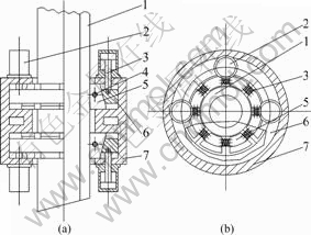
(a) 双层布置图;(b) 钳口分布示意图
1―预制桩;2―液压缸;3―液压缸活塞杆;4―复位弹簧;5―多瓣钳口;6―锥形楔块;7―夹桩箱体
图1 多点均压式夹桩结构原理
Fig.1 Schematic diagram of multipoint and iso-pressing pile clamping mechanism
图1(a)所示表示有2套同样机构沿预制桩的轴线分上下两层对称布置。
液压缸活塞杆伸出时,带动与它联接在一起的锥形楔块运动,锥形楔块的内锥面迫使多瓣结构的钳口同时向中心收缩,由于锥面的增力作用,多瓣钳口从多个方向可靠地夹紧预制桩。液压缸活塞杆缩回时,锥形楔块的内锥面离开多瓣钳口的外锥面,多瓣结构的钳口在复位弹簧的作用下复位,内径增大,便于预制桩的插入。
图1(b)所示为多点均压式夹桩机构的俯视图。表示多点均压式夹桩机构的夹桩液压缸和钳口绕预制桩的分布情况。压桩时,压桩液压缸产生的压桩力通过夹桩箱作用在夹桩钳口上,以整机的重量作为外力,预制桩在压桩力和夹桩摩擦力作用下克服土壤的阻力而被压入土壤里。
2 参数化模型的建立
参数化建模[10]是通过结构几何特征数据,快速构造和修改产品的造型方法,是实现设计、分析自动化的主要手段之一,适用于基本结构形状相同,但特征参数要求可变的系列产品建模与分析。
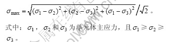
由于在夹桩力和压桩力及重力作用下,夹桩机构各点一般为复杂应力状态,夹桩机构所采用的材料都具有较好延性的钢材,作为强度评判的一般应采用第四强度理论[11],其折算应力或等效应力σmax计算公式为:
夹桩时,夹桩钳口与预制桩的接触是弹性内圆柱面与轴线平行的弹性外圆柱面的接触。预制桩为预应力高强混凝土管桩(PHC桩)[12],外径为500 mm,内径为300 mm,弹性模量为38 GPa, 泊松比为0.2,密度为2 602 kg/m3。夹桩机构的密度为7 800 kg/m3。由于夹桩机构复杂,且圆周对称分布,以16个夹桩液压缸的夹桩机构为例,取其中的1/8进行有限元分析;为了便于对夹桩机构进行有限元分析,对夹桩机构进行参数化建模,对夹桩机构的弹性模量E、泊松比ν、夹桩力F、压桩力P进行了参数化输入。弹性模量E的预设值为200 GPa、泊松比ν的预设值为0.25,夹桩力F的预设值为490 kN,压桩力P的预设值为0 kN。对夹桩机构采用自由网格划分生成体单元网格模型,夹桩参数化建模的网格划分结果如图2所示,共有7个物体,9个接触面。为了实现具有相同结构夹桩机构的系列化、规范化分析,使得重复而又复杂的有限元前处理、求解和后处理变得简单易用,利用内嵌的有限元参数化程序设计语言APDL编辑了压桩机构有限元分析命令流。
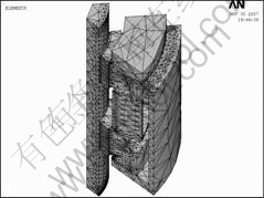
图2 夹桩机构模型
Fig.2 Model of pile clamping mechanism
3 有限元仿真结果
利用APDL编辑的夹桩机构命令流有限元程序,改变参数化项中的1项或几项进行夹桩机构有限元仿真,即可得到一系列结果。利用APDL编辑的夹桩机构命令流式程序,对夹桩、压桩时的夹桩机构进行系列化有限元仿真分析,分别得出夹桩机构的等效应力云图[13]、最大等效应力及最大合位移。
3.1 夹桩状态
当参数化项为预设值,在夹桩状态下,夹桩机构有限元仿真的等效应力云图如图3所示,图中的最大等效应力也就是夹桩机构的最大等效应力M。夹桩机构的合变形如图4所示,图中的最大变形也就是夹桩机构的最大变形s。夹桩机构的最大等效应力和最大变形随夹桩机构的弹性模量E、泊松比ν、夹桩力F的变化如表1~3所示。
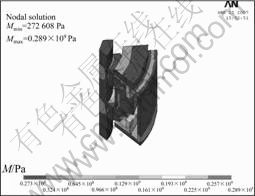
图3 夹桩时夹桩机构的等效应力云图
Fig.3 Cloud diagram of Von Mises stress of pile clamping mechanism under pile clamping
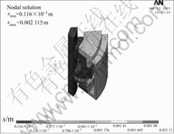
图4 夹桩时夹桩机构的合变形图
Fig.4 Displacement vector sum of pile clamping mechanism under pile clamping
表1 夹桩时最大等效应力和变形随夹桩机构的弹性模量的变化
Table 1 Maximal Von Mises stress and displacement vector sum vs elastic modulus of pile clamping mechanism under pile clamping
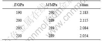
表2 夹桩时最大等效应力和变形随夹桩机构的泊松比的变化
Table 2 Maximal Von Mises stress and displacement vector sum vs Poisson’s ratio of pile clamping mechanism under pile clamping

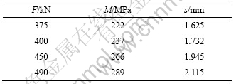
表3 夹桩时最大等效应力和变形随夹桩力的变化
Table 3 Maximal Von Mises stress and displacement vector sum of pile clamping mechanism vs pile clamping force under pile clamping
3.2 压桩状态
当参数化项为预设值时,在压桩力为780 kN的压桩状态下,夹桩机构有限元仿真的等效应力云图如图5所示,夹桩机构的合变形如图6所示,最大等效应力和最大变形随夹桩机构的弹性模量E、泊松比ν、夹桩力F、压桩力P的变化如表4~7所示。
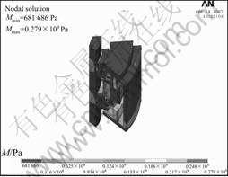
图5 压桩时夹桩机构的等效应力云图
Fig.5 Cloud diagram of Von Mises stress of pile clamping mechanism under pile driving
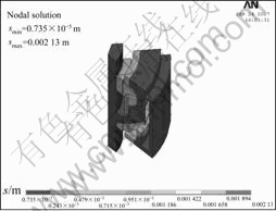
图6 压桩时夹桩机构的合变形图
Fig.6 Displacement vector sum of pile clamping mechanism under pile driving
表4 压桩时最大等效应力和变形随夹桩机构的弹性模量的变化
Table 4 Maximal Von Mises stress and displacement vector sum vs elastic modulus of pile clamping mechanism under pile driving
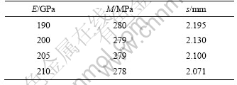
表5 压桩时最大等效应力和变形随夹桩机构的泊松比的变化
Table 5 Maximal Von Mises stress and displacement vector sum vs Poisson’s ratio of pile clamping mechanism under pile driving
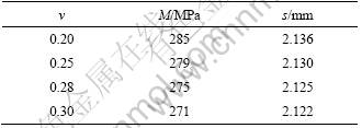
表6 压桩时夹桩机构的最大等效应力和变形随夹桩力的变化
Table 6 Maximal Von Mises stress and displacement vector sum of pile clamping mechanism vs pile clamping force under pile driving
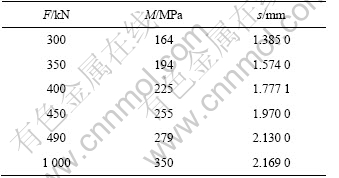
表7 压桩时夹桩机构的最大等效应力和变形随压桩力的变化
Table 7 Maximal Von Mises stress and displacement vector sum of pile clamping mechanism vs pile driving force under pile driving

4 仿真结果的分析与研究
由图3~6可知,夹桩、压桩时,夹桩机构的等效应力及位移分布不同,即夹桩、压桩时,夹桩机构的受力状态不相同。
由表1和表4可知,随着夹桩机构弹性模量的增大,夹桩、压桩时,夹桩机构的最大等效应力略微减小,最大变形明显减少;即夹桩机构的弹性模量对夹桩机构的最大等效应力影响小,对夹桩机构的最大变形影响大。
由表2和表5可知,随着夹桩机构泊松比的增大,夹桩、压桩时的夹桩机构的最大等效应力减小,最大变形略减少;即夹桩机构的泊松比对夹桩机构的最大等效应力影响较大,而对夹桩机构的最大变形影响小。
由表3和表6可知,随着夹桩力增大,夹桩和压桩时的夹桩机构最大等效应力和最大变形明显增加;即夹桩力对夹桩和压桩时的夹桩机构的最大等效应力和最大变形影响大。
由表7可知,随着压桩力的增加,压桩时夹桩机构的最大等效应力减少,最大变形增加。
5 结 论
a. 夹桩、压桩时的夹桩机构的等效应力及位移分布不同,受力状态也不相同。
b. 为了减少液压静力压桩机夹桩、压桩时的夹桩机构最大等效应力,可采取增大夹桩机构的压桩力和泊松比以及在保证能正常压桩条件下,适当减小夹桩力等措施。
c. 为了减少液压静力压桩机夹桩、压桩时的夹桩机构最大合变形,可采取增大夹桩机构的弹性模量,减小夹桩机构的压桩力,以及在保证能正常压桩条件下,适当减小夹桩力等措施。
参考文献:
[1] 张明义. 静力压入桩的研究与应用[M]. 北京: 中国建材工业出版社, 2004: 2-4.
ZHANG Ming-yi. Study and application of static driving pile[M]. Beijing: China Building Material Industry Publishing House, 2004: 2-4.
[2] 朱建新, 何清华. 液压静力压桩机的技术及发展[J]. 工程机械与维修, 2004(7): 72-74.
ZHU Jian-xin, HE Qing-hua. Technique and development of hydraulic static pile driver[J]. Construction Machinery and Maintenance, 2004(7): 72-74.
[3] ZHOU Xu, HE Qing-hua, ZHU Jian-xin, et al. Research on the capacity of hydraulic pile driving under adding force[C]// Proceedings of the 2007 IEEE International Conference on Mechatronics and Automation. New York, 2007, Ⅲ: 2032-2036.
[4] 徐至钧, 李智宇. 预应力混凝土管桩基础设计与施工[M]. 北京: 机械工业出版社, 2005: 347-350.
XU Zhi-jun, LI Zhi-yu. Base design and construction of pre-fabricated concrete piles[M]. Beijing: China Machine Press, 2005: 347-350.
[5] 姜 渭. 抱压式液压静力沉桩机夹桩机构的改进设计[J]. 红河水, 2005, 24(4): 24-27.
JIANG Wei. Renovated design of the pile clipping of holding type hydraulic static pile presser[J]. Hongshui River, 2005, 24(4): 24-27.
[6] 罗春雷, 胡均平, 朱桂华. 液压静力沉桩机夹桩系统的力学研究[J]. 工程机械, 2002(2): 9-12.
LUO Chun-lei, HU Jun-ping, ZHU Gui-hua. Mechanical study of pile clamping system for static pile-pressing machine[J]. Construction Machinery and Equipment, 2002(2): 9-12.
[7] 朱桂华. 液压静力沉桩机夹桩机构研究设计[J]. 建筑机械, 2003(2): 37-38.
ZHU Gui-hua. Study and design of pile clamping device for static pile pressing machine[J]. Construction Machinery, 2003(2): 37-38.
[8] 胡均平, 贺淑云, 罗春雷, 等. 液压静力沉桩机钳口调心结构的研究[J]. 矿冶工程, 2002, 22(3) : 23-25.
HU Jun-ping, HE Shu-yun, LUO Chun-lei, et al. Alignment structure of the pile pincers of hydrostatic pile drivers―A study[J]. Mining and Metallurgical Engineering, 2002, 22(3): 23-25.
[9] 朱建新, 何清华, 林宏武, 等. 液压静力压桩机多点均压式夹桩机构的设计与研究[J]. 建筑机械, 2006(5): 66-69.
ZHU Jian-xin, HE Qing-hua, LIN Hong-wu, et al. Research and design on multipoint and iso-pressing pile holder mechanism[J]. Construction Machinery, 2006(5): 66-69.
[10] 李 伟, 陈国明. U型ACFM激励探头的仿真分析[J]. 系统仿真学报, 2007, 19(14): 3131-3134, 3162.
LI Wei, CHEN Guo-ming. Simulation analysis of U-shape inducer for ACFM[J]. Journal of System Simulation, 2007, 19(14): 3131-3134, 3162.
[11] 罗永要, 王正伟, 梁权伟. 混流式水轮机转轮动载荷作用下的应力特性[J]. 清华大学学报: 自然科学版, 2005, 45(2): 235-237, 257.
LUO Yong-yao, WANG Zheng-wei, LIANG Quan-wei. Stress of Franc is turbine runners under fluctuant work conditions[J]. Journal of Tsinghua University: Science and Technology, 2005, 45(2): 235-237, 257.
[12] GJBT―644. 预应力混凝土管桩[S]. 2003: 11-12.
GJBT―644. Pre-fabricated concrete piles[S]. 2003: 11-12.
[13] 唐应时, 占良胜, 方其让, 等. 基于动态仿真的副变速器箱体有限元分析[J]. 中南大学学报: 自然科学版, 2006, 37(4): 769-774.
TANG Ying-shi, ZHAN Liang-sheng, FANG Qi-rang, et al. Finite element analysis of sub-transmission case based on dynamic analysis[J]. Journal of Central South University: Science and Technology, 2006, 37(4): 769-774.
收稿日期:2008-03-10;修回日期:2008-05-08
基金项目:国家“863”计划资助项目(2003AA430200)
通信作者:周 旭(1964-),男,湖南湘潭人,博士研究生,高级工程师,从事工程机械液压传动及机电液集中控制研究;电话:0731-8836046;E-mail: xuzhouzx@163.com

