�����ӻ����۷�Ti-6Al-4V�Ͻ�ԭλ�������������֯��Ӧ����Ӧ�ĵ��ӱ�ɢ���������
��Դ�ڿ����й���ɫ����ѧ��(Ӣ�İ�)2014���12��
�������ߣ�Martin BORLAUG MATHISEN Lars ERIKSEN Yingda YU Ola JENSRUD Jarle HJELEN
����ҳ�룺3929 - 3943
�ؼ��ʣ�Ti-6Al-4V�Ͻ𣻵������죻���ӱ�ɢ�����䣻ԭλ���죻�����ӻ����۷�����֯�����Ա���
Key words��Ti-6Al-4V alloy; additive layer manufacturing; electron backscatter diffraction; in-situ tensile test; plasma arc welding; microstructure; plastic deformation
ժ Ҫ�����켶�ѺϽ�����͵������켼��(ALM)�����������ڽϵ͵�����ɱ��ȷ��棬���������ͳ�ӹ������ա��ɵ����ӻ����۷�������켼���Ʊ�Ti-6Al-4V�Ͻ������֯�ɶ������������Ħ���״�������侧��������ϸС�Ħ�Ƭ����֯���ɡ���ԭλ��������н��Ӧ�ø������ߵ��ӱ�ɢ���������(Offline EBSD)�ɿ��ٻ�ȡ��������֯���α�����֮��Ĺ�ϵ����ʾ�������ȱ��εķ���ȡ������״������Ӧ����Ӧ����״���ƺͻ��滬��ϵͳ��������������������α们���ߣ�����ijЩ��״���л�����չ����������; ������һЩ�����б���Ϊ����Ӧ���ݶȺ�Ӧ�����еĵط������α�ʧ�䡣�α����չϰ�������ڶ���������������״������������֮��Ľ���ȡ���ϵ���ڴ�ֱ����״����������������ʾ���ھ��ҵı��ξ�������ԭλ����۲⼰���ٵ����ߵ��ӱ�ɢ����������������������������۵�����α���չ�Ŀ��ƻ��ơ�
Abstract: Additive layer manufacturing (ALM) of aerospace grade titanium components shows great promise in supplying a cost-effective alternative to the conventional production routes. Complex microstructures comprised of columnar remnants of directionally solidified ��-grains, with interior inhabited by colonies of finer ��-plate structures, were found in samples produced by layered plasma welding of Ti-6Al-4V alloy. The application of in-situ tensile tests combined with rapid offline electron backscatter diffraction (EBSD) analysis provides a powerful tool for understanding and drawing qualitative correlations between microstructural features and deformation characteristics. Non-uniform deformation occurs due to a strong variation in strain response between colonies and across columnar grain boundaries. Prismatic and basal slip systems are active, with the prismatic systems contributing to the most severe deformation through coarse and widely spaced slip lines. Certain colonies behave as microstructural units, with easy slip transmission across the entire colony. Other regions exhibit significant deformation mismatch, with local build-up of strain gradients and stress concentration. The segmentation occurs due to the growth morphology and variant constraints imposed by the columnar solidification structures through orientation relationships, interface alignment and preferred growth directions. Tensile tests perpendicular to columnar structures reveal deformation localization at columnar grain boundaries. In this work connections are made between the theoretical macro- and microstructural growth mechanisms and the observed microstructure of the Ti-6Al-4V alloy, which in turn is linked to observations during in-situ tensile tests.
Trans. Nonferrous Met. Soc. China 24(2014) 3929-3943
Martin BORLAUG MATHISEN1,2, Lars ERIKSEN1, Yingda YU1, Ola JENSRUD1,3, Jarle HJELEN1
1. Department of Materials Science and Engineering, Norwegian University of Science and Technology, Trondheim N-7491, Norway;
2. Eggemoen Aviation and Technology Park, Norsk Titanium AS, Flyplassveien 21, Norway;
3. Department of Materials Technology, Raufoss Technology AS, Raufoss N-2831, Norway
Received 17 October 2013; accepted 18 November 2014
Abstract: Additive layer manufacturing (ALM) of aerospace grade titanium components shows great promise in supplying a cost-effective alternative to the conventional production routes. Complex microstructures comprised of columnar remnants of directionally solidified ��-grains, with interior inhabited by colonies of finer ��-plate structures, were found in samples produced by layered plasma welding of Ti-6Al-4V alloy. The application of in-situ tensile tests combined with rapid offline electron backscatter diffraction (EBSD) analysis provides a powerful tool for understanding and drawing qualitative correlations between microstructural features and deformation characteristics. Non-uniform deformation occurs due to a strong variation in strain response between colonies and across columnar grain boundaries. Prismatic and basal slip systems are active, with the prismatic systems contributing to the most severe deformation through coarse and widely spaced slip lines. Certain colonies behave as microstructural units, with easy slip transmission across the entire colony. Other regions exhibit significant deformation mismatch, with local build-up of strain gradients and stress concentration. The segmentation occurs due to the growth morphology and variant constraints imposed by the columnar solidification structures through orientation relationships, interface alignment and preferred growth directions. Tensile tests perpendicular to columnar structures reveal deformation localization at columnar grain boundaries. In this work connections are made between the theoretical macro- and microstructural growth mechanisms and the observed microstructure of the Ti-6Al-4V alloy, which in turn is linked to observations during in-situ tensile tests.
Key words: Ti-6Al-4V alloy; additive layer manufacturing; electron backscatter diffraction; in-situ tensile test; plasma arc welding; microstructure; plastic deformation
1 Introduction
Cost effective processes for the production of complex titanium alloy components continue to evolve, partly in response to increasing demand within several areas of application. A surge in aircraft production combined with increasing utilization of titanium alloys in modern airframe constructions is an important driving force. The additive manufacturing approach is an obvious avenue to explore as reduced material waste and machining need is especially beneficial for expensive and tough-to-machine aerospace titanium alloys. Airframe structural parts are typically thin-walled with several ribs and pockets. They are traditionally machined from a solid forged billet, often with as much as 80%-90% material waste. Currently, titanium castings have only limited the application for these components due to less favourable mechanical properties.
The mechanical properties of the common titanium alloys greatly depend on the processing and post- processing conditions. In conventional manufacturing, this commonly entails a series of forging and recrystallization heat treatments. The same alloys are currently used with the novel additive manufacturing techniques, for example, the common Ti-6Al-4V alloy which still dominates in many applications. But the same methods for the microstructure manipulation are not readily available. The main barrier is the inherent resistance to the recrystallization in the hexagonal close packed (HCP) crystal structure of ��-Ti. This is in part due to the low symmetry of the HCP cell which makes the relaxation and grain reorientation less likely. The strict adherence to Burger��s orientation relationship [1] also means that any residual ��-Ti at low temperature will grow and recombine to reform the previous ��-grain structure upon reheating [2]. Only heavy deformation with the related stored energy through dislocations giving a driving force for the recrystallization can give this response in Ti-6Al-4V alloy. The typical additive layer manufacturing (ALM) method does not have this mechanical component to the fabrication, and the recrystallized bimodal structure is not obtained.
This means that in-depth understanding of the ALM macrostructure and microstructure is necessary to be able to attain the well balanced properties of the typical forged material. The complexity of the grain structures produced as layer upon layer of material is fused together to further emphasize the need for understanding. Behaviour such as macroscopic strain anisotropy needs to be better understood. The main areas of application, such as aerospace components, naturally involve strict demands for material properties.
The importance of crystal orientation on the deformation in the HCP-structured ��-Ti phase is emphasized by several authors [3-5]. Table 1 shows the identified slip systems in the ��-Ti HCP cell. The three primary slip systems all have slip directions in the basal plane. The systems with basal directions have been shown to be preferential at an angle between c-axis and tensile axis of as little as 14�� [8,9]. This suggests a high critical resolved shear stress (CRSS) for the remaining slip systems. This in turn implies very low plasticity in the crystal under loads parallel to the c-axis, perpendicular to the basal plane.
EBSD analysis yields information on both grain morphology and crystallographic orientation, combined with phase identification. Recent advances in high speed offline EBSD analysis have made it possible to rapidly collect diffraction patterns across large areas. This paves the way for the analysis of intricate structures such as the plasma direct metal deposited (DMD) material, of which fine microstructures within coarser macrostructures make it necessary to combine large area and high resolution for complete characterization, in combination with in-situ tensile tests, i.e. straining the sample in a special SEM stage with EBSD analysis at intermediate elongation values within the straining sequence, typically after every elongation of 0.5%. This provides a powerful tool for acquiring understanding of deformation behaviour in the novel materials.
The material analyzed in this work was produced as test blocks utilizing a method developed for large scale additive manufacturing via a hybrid plasma weld-based, wire-fed deposition process.
2 Experimental
The tensile samples were extracted from large blocks of the deposited material. They were machined into the final tensile specimen geometry shown in Fig. 1 by electric discharge machining.
2.1 Sample preparation
The final polish was performed by alcohol-silica suspension with particles of 0.4 ��m and addition of hydrogen peroxide (H2O2) for mirror finish. Polishing time was 10 min, with rotation speed of polishing cloth of 150 r/min and downward force of approximately 4 N/cm2.
Table 1 Slip systems of HCP structured ��-Ti [6] and relative values for CRSS for Ti-6Al-4V alloy [7]


Fig. 1 Sample block deposit and dimensions of in-situ tensile specimen
Ultrasonic cleaning was performed in an acetone bath for 10 min, followed by 5 min plasma cleaning and a final step of ion milling with a sample tilt angle of 85�� and sputtering time of 5 min to give a light rinse of the sample surface as a finishing step.
2.2 In-situ tensile tests
A special tensile test specimen stage installed in a Zeiss Ultra 55 LE FESEM was used for the combined straining and EBSD analysis. The stage has an externally controlled electromotor exerting the tensile force on the sample. The elongation was measured by a sensor counting revolutions within the straining mechanism.
Typical parameters applied during the combined EBSD and in-situ tensile tests are shown in Table 2. These tests were done in a Zeiss Ultra 55 LE FESEM fitted with a NORDIF UF-1000 ultra fast EBSD detector.
Table 2 Parameters applied during EBSD combined with in-situ straining

Diffraction patterns were collected by NORDIF acquisition software and streamed to hard disc to be indexed later (offline).
2.3 Post processing
The indexing of the results from offline EBSD scans was done in TSL OIM data collection software from EDAX. A classic Hough-transform was employed. The indexed data sets were post-processed in the TSL OIM analysis software to produce various grain maps and graphic representations, as presented in the next chapter.
3 Results and discussion
3.1 Characterization of macrostructure
Figure 2 shows the transition from relatively fine bimodal structure in the base plate, to the more uninhibited growth of large solidification structures in the deposited material. The ��-grains grow along the steepest temperature gradient with preferred growth direction <100>. With the narrow solidification range shown by the Ti-6Al-4V alloy system, the growth of these structures typically proceeds in a very stable manner. This usually results in columnar structures along z-direction (build direction).
This macrostructure has been identified as a common occurrence in most ALM processes, including laser melting and powder based methods [11,12].
The columnar solidification structures often span several layers in the deposited structure, nucleate in the fusion zone towards the previous layer and build upon these crystals with the same orientation and growth direction. The characteristic epitaxial growth mechanism associates with layered melting deposition techniques. As crystallographic orientation is inherited across layers, ��-grains can grow several millimetres in length.
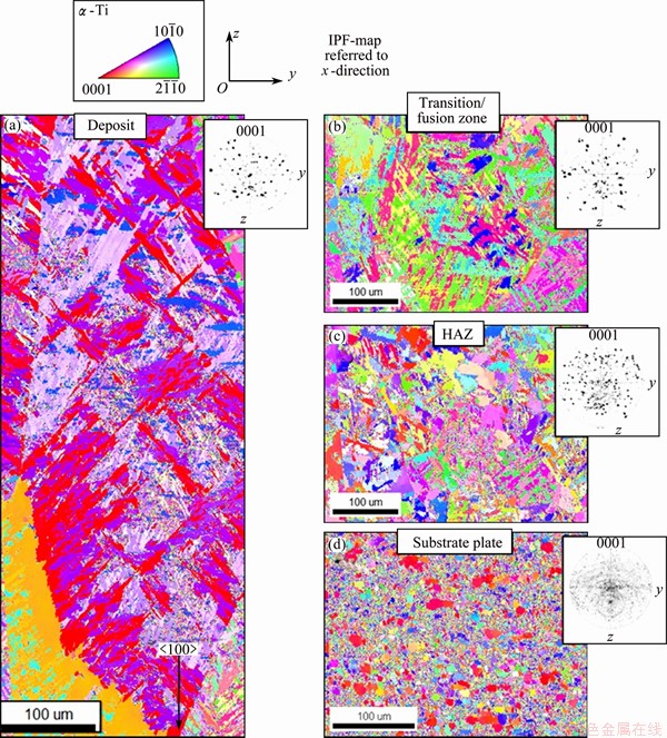
Fig. 2 Evolution of structure from rolled Ti-6Al-4V substrate plate (Fig. 2(d)) towards plasma deposited material (Fig. 2(a)) [10]
It is evident in Fig. 2 that with the pole figures accompanying each region, there are no clear systematic changes in the texture across the substrate-deposit interface. The number of grain orientation variants is however severely limited across large areas in the deposited material. This is because ��-grains with favoured crystallographic facets aligned with the direction of the steepest temperature gradient dominate completely upon the solidification. This is combined with a far reaching influence imparted by the previous ��-grains on the subsequent growth of ��-grains as the allotropic transformation takes place upon cooling. This leads to the reduced crystallographic diversity on the macroscopic scale.
3.2 Characterization of microstructure
The typical microstructures of the alloy are shown in Fig. 3, where the left images show IPF maps (grain orientations illustrated by colors) and the right images show the same areas as IQ maps (Image quality greyscale maps, diffraction signal quality degradation gives outlined grain boundaries). Figures 3(a) and (b) show the typical basket-weaved structure found in the plasma deposited material. Figures 3(c) and (d) show the more blocky grain boundary ��-grains and the colony structures emanating from these grains.
In Ref. [13] the basal planes are aligned along the boundary plane of column grains in a Ti-8Al-xV alloy (V content was graded along the sample). In this study, Ti-6Al-4V alloy, a clear preference for the alignment of prismatic planes with the ��-grain boundary was found. This is exemplified in Fig. 3(c) with unit cells placed each side of the boundary in the top region. Different behaviours could be caused by the high Al content in the referenced study. The addition of Al changes the relative densities of basal and prismatic planes, making basal planes denser and more active as slip planes are at Al content above 6% [8]. This could simultaneously influence the relative surface energies of the facets in the HCP cell. Low energy facets have a tendency to align themselves with the grain boundary plane [13]. The influence of interfaces along previous ��-grains is important considering the columnar nature of these grains, and thus the far reaching implications of such ordered growth.
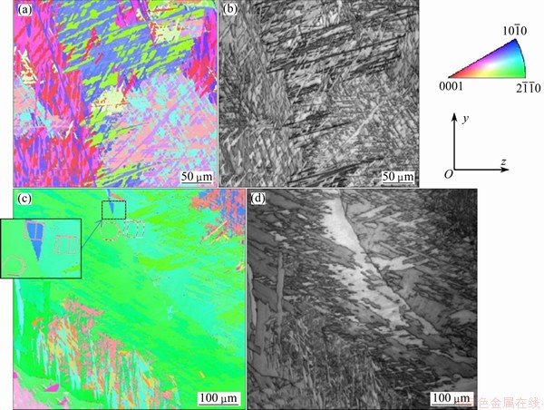
Fig. 3 IPF map of basket-weaved type structures in previous ��-grain interior (a), IQ map of same area showing morphology of plates more clearly as grain boundaries revealed (b), blocky grain boundary ��-phase and colony structures extending from previous ��-grain boundary, and typical alignment of grain boundary ��-phase along previous ��-boundaries illustrated by unit cells overlaid (c) and IQ map of same area as in Fig. 3(c) (d)
Another important factor influencing variant selection for the growth of ��-phase is Burger��s orientation relationship: (110)��//(0002)�� and [111]��//  �� [1]. This is illustrated in Fig. 4(b).
It is typically observed that blocky regions of ��-grain boundary break up into parallel plates extending towards the previous ��-grain interior. The morphology of this structure is dependent on the cooling rate, or essentially the degree of undercooling at the point of transformation. Typical structure with orientation illustrated by overlaid unit cells is shown in Fig. 5.
It is clear that the tendency is, for the long dimension of plates to lie along a direction in the basal plane, perpendicular to c-axis. This is indicated by the fact that the last vector component is zero/near zero for all vectors. This growth configuration is favourable for effective solute shedding and heat transfer during the growth. The structure also exhibits the tendency for plates belonging to different colonies to have their long dimensions perpendicular to each other, as would be expected after sympathetic nucleation. Sympathetic nucleation, meaning the formation of secondary colonies at the boundary of existing colonies, is favoured at higher undercooling and gives rise to the basket-weaved type structures. The perpendicular arrangement of plates serves to minimize elastic strains during growth. The extremely high aspect ratio of the grains could partly be explained by a mechanism observed in Ref. [15], whereby large ��-grain sizes retard the transformation into ��-phase towards a lower temperature due to the inherent stability of the coarser grains. The lower temperature in turn gives the reduced diffusion rates, which will exacerbate the need for lateral diffusion over the shorter diffusion lengths.

Fig. 4 Generally 60�� misorientations (highlighted green) dominating within ��-plate colony structures, while 90�� misorientations (highlighted red) typically found across columnar previous ��-grains (a) and misorientations appearing within constraints of Burger��s orientation relationship [14] (b)
Figure 6 illustrates how adherence to the growth constraints imposed throughout columnar structures can help rationalize the occurrence of often observed microstructural arrangements.
This long range microstructural bias is significant for the strain response in the plasma DMD material, and represents common ground for many ALM techniques.
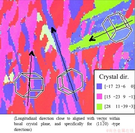
Fig. 5 Adherence to preferred growth direction of plates
3.3 Phase composition
The detected amount of residual ��-phase is as low as 1% in most scans. As ��-phase is expected to be found in thin layers at grain boundaries, non-detection can occur with EBSD as the diffraction pattern quality is diminished near the interfaces. Sample preparation can also lead to artificially low ��-phase on the surface. The martensitic reaction proceeds at relatively low stress levels. The ��back stress��, meaning the forces opposing the shear based martensitic transformation, is fairly modest. This again means that any retained, metastable ��-phase which has a chemical driving force for transformation to ��-phase, can undergo a transformation to martensite assisted by applied stress or deformation. It has been reported that such transformations can occur during mechanical grinding and polishing of titanium samples [16]. This would obscure the actual phase contents. The issue of detecting this is also complicated. The fine martensitic structures are difficult to resolve and be identified by EBSD techniques, although STANFORD and BATE [17] managed to distinguish martensitic needles with high resolution EBSD scans on the etched samples of Ti-6Al-4V.
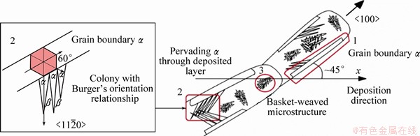
Fig. 6 Schematic illustrating grain growth constraints producing observed microstructures [10]
3.4 In-situ tensile tests
Figure 7 shows stress-strain curves for samples strained along three primary directions (x, y and z, where x is along weld beads, y is the horizontal transverse of beads, and z is the vertical build direction, see Fig. 1). The in-situ tensile stage equipment does not give exact elongation measurements. Elongation is calculated from rotations of the electromotor in this setup. Upon straining, tightening and/or clamping effects give more elasticity than material properties suggest. Elastic modulus of about 115 GPa is expected in the material.
All elongation measurements are only used for approximately relative comparison between samples. The general trends in the stress-strain values support previous full scale quantitative tensile tests where directions x and y exhibit slightly increased strength but significantly reduced ductility.
3.5 Strain response during in-situ tensile tests
Large area comboscans over the complete gauge length after straining along x- and z-directions are shown in Figs. 8 and 9, respectively.
With the samples extracted along x-direction, the columnar grains are oriented more or less perpendicular to the tensile direction. There is local necking towards the right hand region of the tensile sample.

Fig. 7 Stress-strain curves for samples in three primary directions
For the tensile specimens extracted along z-direction, the strained area is typically comprised of only a handful of individual columnar grains.
Figure 10 represents an attempt to envisage how slip activity is connected to stress state and active prismatic slip systems in the constricted region in a sample at an elongation of 5% along x-direction.

Fig. 8 Large area EBSD comboscan for xz-type specimen exhibiting segmented deformation at elongation of 5%, with local necking

Fig. 9 Large area EBSD comboscan for zx-type specimen without any obvious signs of deformation at elongation of 5%

Fig. 10 Grain orientations giving high Schmid factor for prismatic slip upon tensile forces (see IPF figure with colour gradient and Schmid factor contour plot to right [18]) (a), grain orientations giving high Schmid factor for prismatic slip upon compressive forces (b) and surface appearance at elongation of 5% (stitched image, SE detector)
By highlighting certain orientation measurements in the post analysis software, the regions with high Schmid factor for prismatic slip are identified. The highest values of 0.5 are coloured blue, while green, yellow, orange and red follow in the sequence towards lower Schmid factor. The areas that fall outside this colour gradient are more resistant towards the activation of prismatic systems.
The complex tri-axial stress state introduced by necking would impart a compressive stress component along the width of the tensile specimen. Orientations favouring basal slip are more evenly spread out across the sample. Therefore, the prevalence of easily activated prismatic slip planes in certain segments is identified as a significant feature. The highlighted regions seem to coincide quite accurately with the areas of most severe deformation. Orientation data are assumed to be reliant, even if severe deformation and surface topology degrade and deflect the EBSD signal. The orientations indicated in the scan performed post-strain match what was achieved pre-strain quite accurately. This does not seem to be significant reorientation of grains in response to the strain. Some discussion on surface topology and its influence on reliability were presented in Ref. [19].
The sample exhibits heavy slip along prismatic planes, counteracted by slip resistance and stress build-up in differently oriented grains. Localized heavy strain hardening is expected to occur in the necked region, at columnar grain interfaces especially. This would contribute to the crack formation if further plastic deformation is not accommodated in other segments of the sample.
The in-situ test results of this sample are shown in Fig. 11 (see Fig. 8 for the position of the analyzed area on the sample). The area lies at the border between the right hand side of the sample, associated with severe deformation, and the left of the sample, showing minimal signs of deformation. Here, the deformation mechanism in a similar colony to the cracked area was observed directly (see Fig. 12 for the identification of important grain orientations and active slip systems during straining).
At an elongation of 3% slip lines appear in grains of type 5 and type 7a. Type 5 is oriented for prismatic slip. Type 7a has the highest Schmid factor for pyramidal system, and lies at equal Schmid factor for prismatic and basal systems. The determination of slip mechanism is difficult by just tracing the slip lines. Slip transmission seems to occur readily within the left side of colony structure along the long dimension of plates (see Fig. 13 for an example of this).
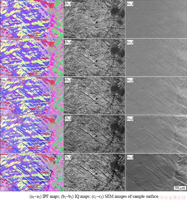
Fig. 11 In-situ straining sequence for specimens at elongations of 2.5% (a1, b1, c1), 3.0% (a2, b2, c2), 3.5% (a3, b3, c3), 4.0% (a4, b4, c4) and 5.0% (a5, b5, c5) (Area is marked in Fig. 8)

Fig. 12 Regions analyzed in-situ for presented xz-type sample
No clear indication of cross-slip (alteration between slip planes [20]) is observed, although the slip line is not strictly straight. This is shown in Fig. 13. The deviations in the slip lines are attributed to the stored geometrically necessary dislocations (GNDs) in Ref. [19]. A schematic diagram illustrating the generation of these dislocations is shown in Fig. 14.

Fig. 13 Slip line traversing colony plates (IPF map overlaid with IQ greyscale values)

Fig. 14 Illustration of geometrically necessary dislocations compensating for inhomogeneous strain to maintain structural continuity
A clear distinction is exemplified by the in-situ straining sequence shown in Fig. 11. The colonies/ regions within a previous ��-grain where dislocations are readily transmitted appear to have a uniform response to the imposed strain and in a sense act as a single microstructural unit, analogous to the common definition of a grain. The basket-weaved structure on the right side in the analyzed area shows a more mismatched response, generating GNDs and giving local strain hardening.
SAVAGE et al [22] reported a tendency for easy shearing of interlamellar ��-phase and slip transmission in the colonies oriented for prismatic slip, while in the colonies oriented for basal slip fine, homogeneous slip lines and no slip transmission exhibit. The finely spaced slip lines of the basal system show the increase of strain hardening due to the higher cross slip rate and stronger slip band interaction. This non-planar slip increases the dislocation density, and likely occurs in the right side region in Fig. 11, with the pink grains most likely exhibiting the deformation by basal planes. Figure 12 shows Schmid factors for different planes.
Strain hardening is caused by the accumulation of dislocations locally at interfaces or in the grain interior (see Fig. 14 for a schematic representation). These dislocations act as effective barriers against further dislocation movement, as pile-ups produce a back stress opposing the dislocation motion [20]. All metals contain an appreciable amount of dislocations prior to any deformation. This stems from the growth of the crystals and some ever-present misalignment of the growth which will always occur due to tiny shifts in gradients of temperature or composition [20]. The irregularities associated with large angle grain boundaries (ledges and steps) will cause the emission of dislocations in early stages of plastic flow. The effect of the grain size and interstitial solutes on strain hardening is through their influence on dislocation density [23]. This means that the interfaces such as grain boundaries do not have any intrinsic increase in strength, but provide a hardening effect as they interfere with slip systems within and across grains, and also generate dislocations at boundaries. Figure 14 illustrates the model for macroscopic deformation of microscopically anisotropic polycrystals, proposed by ASHBY [21]. The transition along previous ��-grain boundaries is seen to cause the stress along with strain gradients, leading to severe dislocation pile-ups and eventually leading to the fracture along this interface. This can be observed in Fig. 9, where a softer segment outlined by previous ��-grain boundaries appears to accommodate severe plastic deformation and produce cracking towards the neighbouring previous ��-grain to the left. The smaller ��-grain on the left contains colony structures less favourably oriented for prismatic slip activity, giving significantly mismatched strain response across this interface.
Figure 15 shows the optical microscope images of the strained sample surface.
Different characteristics of the crisscross, broken up strain accommodation in the left basket-weaved type region, and the more uniform, less restrained deformation in the coarse colony structures produce a series of ledges and steps at the interface. Ledges and steps on the surface indicate that the geometrically necessary dislocations have been transmitted transverse to the strain direction and exiting the sample surface [19].
Finer grains or microstructural units, would encompass more grain boundary area, thereby producing higher dislocation density and greater strain hardening. The lower strength of coarse grain microstructures is commonly attributed to a higher degree of local dislocation pileups at grain boundaries in large grains, as the number of dislocations along a slip plane is proportional to the grain size [6]. The dislocation generation at boundaries is put forth as the primary mechanism for grain boundary strengthening in Refs. [21] and [23]. During the plastic flow, the cross section area of a tensile specimen is constricted. If the strengthening due to strain hardening is not enough to compensate for the reduced cross-sectional area, the instability and local necking will occur [20], as observed in Fig. 8. The strain hardening can be assumed to occur mainly very locally at the interface between columnar segments, while the bulk of the softer segment continues to accommodate less restrained plastic deformation until the fracture occurs at the boundary.
The build-up of strain gradients at boundaries due to mismatch in deformation characteristics was predicted in Ref. [19]. This heterogeneous deformation can lead to brittle fracture in Ti-6Al-4V alloy. This phenomenon is seen at an elongation of 5% in Fig. 11, where large dark areas indicate the accumulation of dislocations accompanied by stress concentration to the point of fracture initiation.
Across the previous ��-grain boundary the  -type morphology exhibits less uniform dislocation movement. This illustrates how mismatch in neighbouring regions leads to local accumulation of GNDs to uphold strain gradients.
No discernible features appear in Fig. 9 after straining to an elongation of 5% and the sample seems to exhibit fairly homogeneous deformation.
Figure 16 shows the sequence of in-situ scans (the area analyzed in-situ is indicated in Fig. 9).
Figure 16 shows slip transmission across a previous ��-grain boundary. There are some evidences of stress build-up and strain gradients across the boundary, but the slip seems to be transmitted quite easily without much mismatch and generation of dislocations.
The tensile sample perpendicular to the welded layers (plane zx) displayed the lowest yield strength (Fig. 7). The overall texture plots of the strained areas are presented in Fig. 17.
Although these plots could serve to explain the lower strength in plane zx, the previous discussion showed that pronounced heterogeneous deformation mechanisms dominate. The moderate two-component texture in plane zx does indicate easy activation of prismatic and basal systems in large areas of the sample. As the zx sample area is strongly dominated by few (two) columnar previous ��-grains, the uniform deformation characteristics of the colony structure would give very little deformation mismatch, grain interaction and work hardening.
As is illustrated in Fig. 5, plates grow along the favoured basal slip directions, contributing to the effective dislocation movement in the coarser colony structures. Figure 18 illustrates the importance of the spatial orientation of plates.
Figure 18, cropped from the bottom right of the analyzed area in Fig. 11, shows how a perpendicular plate intersecting the colony structure acts as a barrier to deformation movement. At an elongation of 5% the perpendicular plate appears significantly brighter for a map overlaid with kernel average misorientation greyscale values. This indicates a strain gradient across the plate, upheld by GNDs at the boundaries and likely elastic strain within the grain. Misorientation plots measured along the multicolour line indicated across the plate show how the misorientation is altered by straining. The effect is the most prominent at the grain boundaries, which is in line with the theory of GND accumulation suggested in Fig. 14. The IQ map at an elongation of 5% (Fig. 18(b1) and (b2)) shows how a slip band propagates through the perpendicular plate only after heavy build-up of dislocations. This shows the strengthening effect of a relatively low angle grain boundary of about 10��.

Fig. 15 Mismatched strain response across previous ��-grains showing local strain accumulation
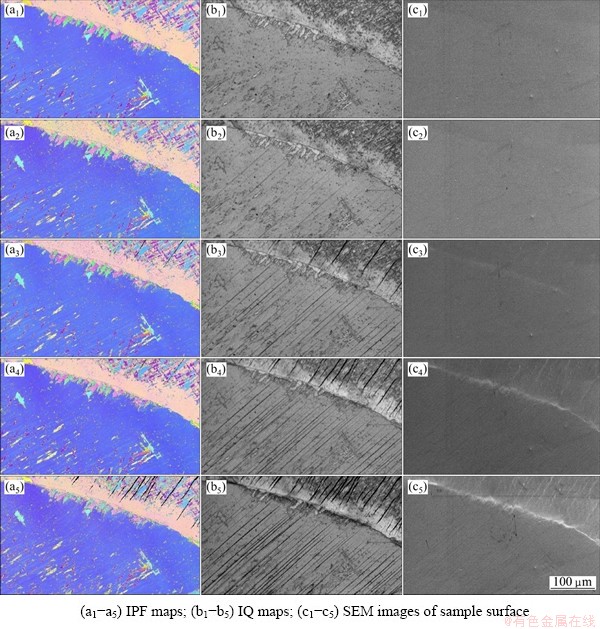
Fig. 16 In-situ strain sequence for specimen at elongations of 2.0% (a1, b1, c1), 2.5% (a2, b2, c2), 3.0% (a3, b3, c3), 4.0% (a4, b4, c4) and 5.0% (a5, b5, c5)
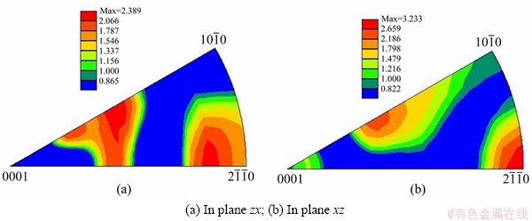
Fig. 17 Texture plots for tensile samples (referred to stress axis)
��-Ti exhibits higher strength than ��-Ti within two-phase microstructures. It is up to 3 times harder than ��-Ti [24]. The studies of single colony deformation in ��+�� alloys focus on the transmission of slip across interlamellar ��-phase. The observed anisotropy in colonies is attributed to the direction of slip in relation to ��-platelets. The slip normal to platelets is more difficult [24]. Anisotropy beyond what can be explained by Schmid factors or texture is observed in this study. The direction of slip compared to the spatial orientation of colony plates is a significant factor, which could warrant further investigation of the platelet interfaces and the influence of retained ��-phase in the plasma DMD material by TEM methods. This also suggests that the reduction of colony size is beneficial to the mechanical properties.
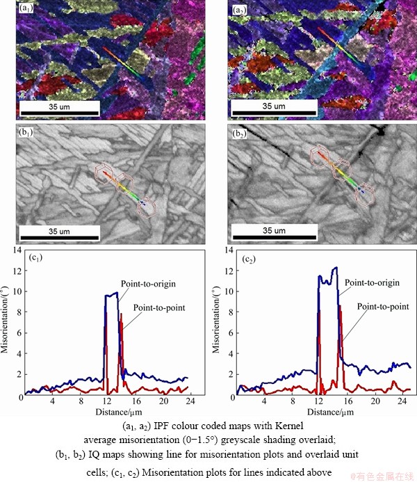
Fig. 18 Comparison of sections of scan at elongations of 0 (a1, b1, c1) and 5% (a2, b2, c2)
4 Conclusions
1) The combination of an in-situ tensile testing rig and high speed EBSD data collection allows for extensive insight into the intricacies of the plasma DMD microstructure of Ti-6Al-4V alloy and its behaviour during loading. The deformation behaviour observed at the microscopic level has significant bearing on the macroscopic strain response. This is caused by the far-reaching influence of columnar solidification structures, brought about by unidirectional heat flow and epitaxial growth. Through preferred growth directions, energetically favourable crystallographic alignment and strict adherence to Burger��s orientation relationship, certain types of colony structures are repeatedly produced.
2) The most severe deformation is associated with prismatic slip along coarse, widely spaced slip bands. Certain colonies act as microstructural units, where colony-wide slip occurs readily. While regions of basket-weaved or Wiedmanstatten-type structures often exhibit more internal deformation mismatch leading to local stress concentration and strain gradients. The surface topography on the polished specimen and diffraction pattern degradation suggest the generation of geometrically necessary dislocations which give strain hardening in these structures.
3) The spatial orientation of plates within a colony is of great importance for the dislocation motion. Slip lines are often restricted to the long dimension of plates, where the slip length is large and orientation is frequently favourable due to the preferred growth direction of plates.
4) Coarse grain boundary ��-phase does not appear significantly weaker than coarse colonies or Wiedmanstatten structures, but heterogeneous behaviour is often seen to give local strain gradients across interfaces with associated dislocation accumulation and stress build-up.
5) At the macro level, inhomogeneous deformation gives segmented strain response. With the stress axis perpendicular to the columnar previous ��-grains (x-direction), deformation may be accommodated predominately in column grains inhabited by the softer colonies. This would produce local strain hardening, and seemingly stronger but less ductile samples in x-direction. These structures are susceptible to premature failure at interfaces between softer regions and regions less favourably oriented for plastic deformation.
6) Loading along previous ��-grains (z-direction) gives more uniform deformation and higher ductility but lower strength due to slight macrotexture effects and less strain hardening. Here deformation is not as restrained by boundaries giving more linear slip and less local dislocation accumulation (hardening).
References
[1] BURGERS W G. On the process of transition of the cubic-body- centered modification into the hexagonal-close-packed modification of zirconium [J]. Physica, 1934, 1(7-12): 561-586.
[2] IVASISHIN O M, TELIOVICH R V. Potential of rapid heat treatment of titanium alloys and steels [J]. Materials Science and Engineering A, 1999, 263(2): 142-154.
[3] BETSOFEN S Y, ILYIN A A, PLIKHUNOV V V, PLOTNIKOV A D, FILATOV A A. Texture and anisotropy in the mechanical properties of titanium alloys caused by the mechanism of plastic deformation [J]. Russian Metallurgy, 2007(5): 387-393.
[4] DUNNE F P E, WALKER A, RUGG D. A systematic study of hcp crystal orientation and morphology effects in polycrystal deformation and fatigue [J]. Proceedings of the Royal Society A: Mathematical, Physical and Engineering Science, 2007, 463(2082): 1467-1489.
[5] DUNNE F P E, RUGG D, WALKER A. Length scale-dependent, elastically anisotropic, physically-based hcp crystal plasticity: Application to cold-dwell fatigue in Ti alloys [J]. International Journal of Plasticity, 2007, 23(6): 1061-1083.
[6]  HARDERS H. Mechanical behaviour of engineering materials: Metals, ceramics, polymers, and composites [M]. Heidelberg: Springer-Verlag, 2007.
[7] PATON N E, WILLIAMS J C, RAUSCHER G P. The deformation of alpha-phase titanium[C]//JAFFEE R I, BURTE H M, eds. Proceedings of the Second International Conference on Titanium Science and Technology. New York: Plenum Press, 1973: 1049-1069.
[8] WILLIAMS J, BAGGERLY R, PATON N. Deformation behavior of HCP Ti-Al alloy single crystals [J]. Metallurgical and Materials Transactions A, 2002, 33(13): 837-850.
[9] SZCZEPANSKI C J. The role of microstructural variability on the very high cycle fatigue lifetime variability of the alpha+beta titanium alloy, Ti-6Al-2Sn-4Zr-6Mo [D]. Michigan: The University of Michigan, 2008.
[10] ERIKSEN L. Combined EBSD-investigations and in-situ tensile tests of a direct metal deposited Ti-6Al-4V-alloy [D]. Trondheim: Norwegian University of Science and Technology, 2013.
[11] KOBRYN P A, MOORE E H, SEMIATIN S L. Effect of laser power and traverse speed on microstructure, porosity, and build height in laser-deposited Ti-6Al-4V [J]. Scripta Materialia, 2000, 43(4): 299-305.
[12] BAUFELD B, BIEST O V D, GAULT R. Additive manufacturing of Ti-6Al-4V components by shaped metal deposition: Microstructure and mechanical properties [J]. Materials & Design, 2010, 31: s106-s111.
[13] BANERJEE S, MUKHOPADHYAY P. Phase transformations: examples from titanium and zirconium alloys [M]. Amsterdam: Elsevier, 2007: 813.
[14] BIELER T R, SEMIATIN S L. The origins of heterogeneous deformation during primary hot working of Ti�C6Al�C4V [J]. International Journal of Plasticity, 2002, 18(9): 1165-1189.
[15] GIL F J, GINEBRA M P, MANERO J M, PLANELL J A. Formation of ��- structure: Effects of grain size and cooling rate on the morphologies and on the mechanical properties in Ti6Al4V alloy [J]. Journal of Alloys and Compounds, 2001, 329(1-2): 142-152.
[16]  G, WILLIAMS J C. Titanium [M]. Heidelberg: Springer-Verlag. 2007.
[17] STANFORD N, BATE P S. The martensitic transformation texture in Ti-6Al-4V [J]. Materials Science Forum, 2005, 495-497: 669-674.
[18] BRIDIER F, VILLECHAISE P, MENDEZ J. Analysis of the different slip systems activated by tension in a ��/�� titanium alloy in relation with local crystallographic orientation [J]. Acta Materialia, 2005, 53(3): 555-567.
[19] LITTLEWOOD P D, BRITTON T B, WILKINSON A J. Geometrically necessary dislocation density distributions in Ti-6Al-4V deformed in tension [J]. Acta Materialia, 2011, 59(16): 6489-6500.
[20] DIETER G E, BACON D. Mechanical metallurgy [M]. London: McGraw-Hill, 1988.
[21] ASHBY M F. The deformation of plastically non-homogeneous materials [J]. Philosophical Magazine, 1970, 21: 399-424.
[22] SAVAGE M F, TATALOVICH J, ZUPAN M, HEMKER K J, MILLS M J. Deformation mechanisms and microtensile behavior of single colony Ti-6242Si [J]. Materials Science and Engineering A, 2001, 319-321: 398-403.
[23] OKAZAKI K, CONRAD H. Effects of interstitial content and grain size on the strength of titanium at low temperatures [J]. Acta Metallurgica, 1973, 21(8): 1117-1129.
[24] SURI S, VISWANATHAN G B, NEERAJ T, HOU D H, MILLS M J. Room temperature deformation and mechanisms of slip transmission in oriented single-colony crystals of an ��/�� titanium alloy [J]. Acta Materialia, 1999, 47(3): 1019-1034.
Martin BORLAUG MATHISEN1,2, Lars ERIKSEN1, Yingda YU1, Ola JENSRUD1,3, Jarle HJELEN1
1. Department of Materials Science and Engineering, Norwegian University of Science and Technology, Trondheim N-7491, Norway;
2. Eggemoen Aviation and Technology Park, Norsk Titanium AS, Flyplassveien 21, Norway;
3. Department of Materials Technology, Raufoss Technology AS, Raufoss N-2831, Norway
ժ Ҫ�����켶�ѺϽ�����͵������켼��(ALM)�����������ڽϵ͵�����ɱ��ȷ��棬���������ͳ�ӹ������ա��ɵ����ӻ����۷�������켼���Ʊ�Ti-6Al-4V�Ͻ������֯�ɶ������������Ħ���״�������侧��������ϸС�Ħ�Ƭ����֯���ɡ���ԭλ��������н��Ӧ�ø������ߵ��ӱ�ɢ���������(Offline EBSD)�ɿ��ٻ�ȡ��������֯���α�����֮��Ĺ�ϵ����ʾ�������ȱ��εķ���ȡ������״������Ӧ����Ӧ����״���ƺͻ��滬��ϵͳ��������������������α们���ߣ�����ijЩ��״���л�����չ����������; ������һЩ�����б���Ϊ����Ӧ���ݶȺ�Ӧ�����еĵط������α�ʧ�䡣�α����չϰ�������ڶ���������������״������������֮��Ľ���ȡ���ϵ���ڴ�ֱ����״����������������ʾ���ھ��ҵı��ξ�������ԭλ����۲⼰���ٵ����ߵ��ӱ�ɢ����������������������������۵�����α���չ�Ŀ��ƻ��ơ�
�ؼ��ʣ�Ti-6Al-4V�Ͻ𣻵������죻���ӱ�ɢ�����䣻ԭλ���죻�����ӻ����۷�����֯�����Ա���
(Edited by Wei-ping CHEN)
Corresponding author: Martin BORLAUG MATHISEN; Tel: +47-92893425; E-mail: martin.b.mathisen@norsktitanium.no
DOI: 10.1016/S1003-6326(14)63553-6

