Observation of Bending Behavior of Aluminum Foam Composite Structure Based on Digital Image Correlation Technology
Deng Fan Liu Yanqiang Fan Jianzhong Wei Shaohua Nie Junhui
National Engineering & Technology Research Center for Non-Ferrous Metals Composites,GRINM Group Corporation Limited
GRINM Metal Composites Technology Co.,Ltd.
General Research Institute for Nonferrous Metals
Abstract:
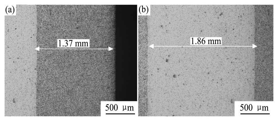
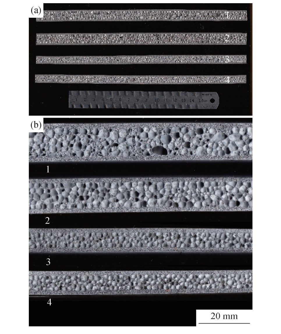
At present,the research on the bending behavior of aluminum foam sandwiches mainly focused on the macroscopic fracture behavior. But there were few researches focusing on the microscopic evolution during the deformation process. Digital image correlation(DIC)technology was a mature technology for directly observing the strain field of materials during deformation,and there were few related reports in the bending process of aluminum foam sandwich panels. So,it had great significance of using DIC technology to observe the characteristics of strain distribution during the bending process of aluminum foam sandwich panels. It was helpful to better understand the difference between the deformation mechanism of aluminum foam sandwich,and the different fracture failure mechanisms between different failure modes. The aluminum foam sandwich panels used in this paper were prepared by powder compact method(PCM). The aluminum foam sandwich panels with different porosity were used in experiment,having a good metallurgical bond between the panel and the foam. The three-point bending experiment was used to test the bending performance of the aluminum foam sandwich panels. A near static bending rate was used in the three-point bending experiment,and the loading rate was 1 mm・min-1,to obtain the bending deformation curves of the sandwich panels. DIC technology was used to obtain the strain distribution field of the sandwich panels sample. According to the mechanical test results,with the increasing of the thickness of foam core the bending strength and fracture deflection of aluminum foam sandwich panel decreased. The bending strength and fracture deflection had a linear relationship with the porosity of aluminum foam core. The failure modes of aluminum foam sandwich panels with different porosity were different. In this experiment,there were two main types:fracture of core shear and fracture of face yield. The sandwich panels with high core porosity,had smaller bending strength and smaller fracture deflection,and the fracture mode was shear fracture of core aluminum foam,the surface aluminum alloy panels were not broken when reaching the maximum bending stress. Aluminum foam sandwich panels with low core porosity had larger flexural strength and larger fracture deflection. And the core aluminum foam was not broken when reaching the maximum bending stress. The two different fracture modes were caused by the different thickness of foam,and the difference core thickness resulted in the location of strain concentration were changed. For the aluminum foam sandwich of lower porosity,the strain concentration areas were formed in the zone near the face panel,and the strain concentration areas were formed in the zone of core foam. The whole deformation process of foam aluminum sandwich panels was observed. It was found that there were certain strain concentration regions in the transition layer between the face panel and the core foam. During the whole process of bending,there was no debonding phenomenon happened between the panel and the foam aluminum. Compared with the aluminum foam sandwich that adhesive bonding between the core and the face,the bonding strength of metallurgical bonding was higher,the load transfer would be better when the bending. It was also a good explanation why the metallurgical bonding of aluminum foam sandwich panels with better mechanical properties. When aluminum foam sandwich panels made from same foamable precursors,the higher the porosity of core aluminum foam,the thicker the sandwich panel would be. And the bending strength and fracture deflection became smaller and smaller with the increase of the thickness of the aluminum foam sandwich panel. The difference core thickness caused the location of the strain concentration region changed,from near the panel(low porosity)to core foam(high porosity). In the bending process,the strain concentration region would appear in the interface between face panel and core aluminum foam,the bonding strength of metallurgical bonding between core and face was higher than that of the adhesive bonding,and there was no debonding occurred between the core and face. And it was a good explanation why the metallurgical bonding of aluminum foam sandwich panels with better mechanical properties.
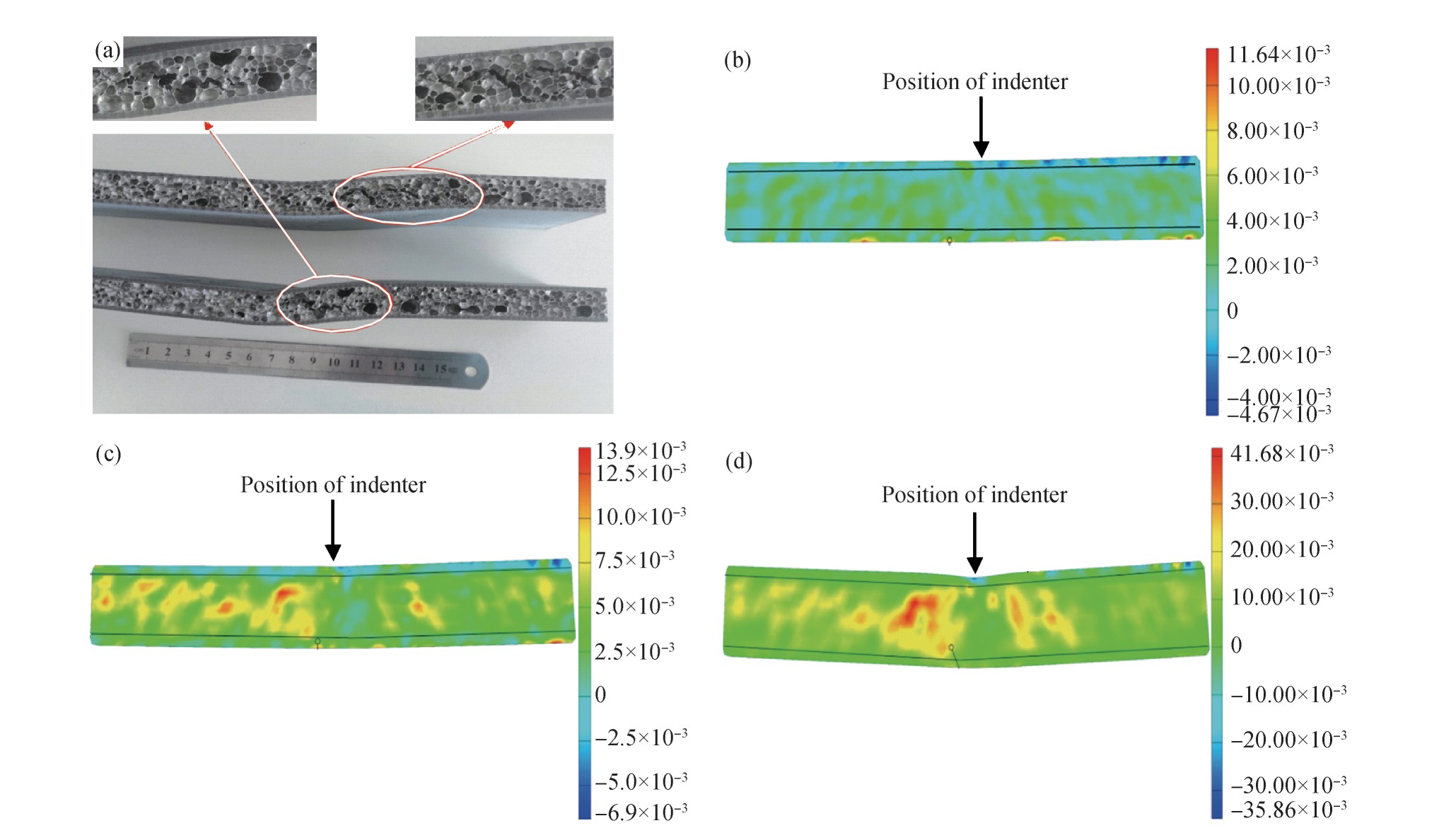
Fig.5 Sample of core shear fracture and strain distribution of Sample 2 during loading
(a)OM image of sample of failure mode core shear;Strain distribution diagram of Sample 2 with different loading:(b)Deflection 1mm;(c)Deflection 2 mm;(d)Fracture(deflection 4.24 mm)(Black line in figure being position of boundary between core and face)
图6 面板屈服断裂样品的宏观形貌和试样4加载过程中应变分布图
Fig.6 Sample of face yield fracture and strain distribution diagram of Sample 4 during loading
(a)OM image of sample of failure mode face yield;Strain distribution diagram of Sample 4 with different loading:(b)Deflection 1mm;(c)Deflection 3 mm;(d)Deflection 6 mm;(e)Fracture(deflection 11.82 mm)(Black line in figure is being position of boundary between core and face)
Fig.8 Strain concentration area of foam aluminum sandwich during bending process
(a)Deflection 4.27 mm;(b)Deflection 7 mm;(c)Deflection 12.4 mm at time of fracture(Black line in figure being position of jointsurface);(d)Microstructure of metallurgical transition layer