J. Cent. South Univ. (2016) 23: 1363-1371
DOI: 10.1007/s11771-016-3188-8

Maglev self-excited vibration suppression with a virtual sky-hooked damper
LI Jin-hui(����)1, 2, LI Jie(���)1, ZHOU Dan-feng(�ܵ���)1, WANG Lian-chun(������)1
1. College of Mechatronics Engineering and Automation, National University of Defense Technology,Changsha 410073, China;
2. Science and Technology on Near-surface Detection Laboratory, Wuxi 214035, China
 Central South University Press and Springer-Verlag Berlin Heidelberg 2016
Abstract: This work addresses the problem of self-excited vibration, which degrades the stability of the levitation control, decreases the ride comfort, and restricts the construction cost of maglev system. Firstly, a minimum model containing a flexible bridge and a single levitation unit is presented. Based on the simplified model, the principle underlying the self-excited vibration is explored. After investigations about the energy transmission between the levitation system and bridge, it is concluded that the increment of modal damping can dissipate the accumulated energy by the bridge and the self-excited vibration may be avoided. To enlarge the equivalent modal damping of bridge, the sky-hooked damper is adopted. Furthermore, to avoid the hardware addition of real sky-hooked damper, considering the fact that the electromagnet itself is an excellent actuator that is capable of providing sufficiently fast and large force acting on the bridge to emulate the influence of the real sky-hooked damper, the technique of the virtual sky-hooked damper is proposed. The principle underlying the virtual sky-hooked damper by electromagnet is explored and the vertical velocity of bridge is estimated. Finally, numerical and experimental results illustrating the stability improvement of the vehicle-bridge interaction system are provided.
Key words: maglev; vehicle-bridge interaction system; self-excited vibration; sky-hooked damper
1 Introduction
Compared with the conventional rail way systems, the electromagnetic maglev system has advantages of lower noise, less exhaust fumes emission, less maintenance cost and the ability to climb steeper slopes, which is a new kind of urban transport that has been widely concerned in recent years [1].
The rapid development and enormous advantages of maglev sketch a bright future for its commercial applications. However, the self-excited vibration of bridge is a burning issue to be solved [2-3]. It occurs when the vehicle is suspended upon the bridge, standing still or moving at very slow speed.It degrades the safety of bridge, and deteriorates the stability of the levitation system.
ALBERT et al [4-5] pointed out that the American Maglev Technologies System achieved successful levitation in Florida on a guideway mounted to the earth on a concrete foundation, but later encountered difficulties in achieving stable levitation when the vehicle was moved to the bridge installed on the Old Dominion University Campus. It was believed that the flexibility of the bridge on the Old Dominion University campus, which employed 90-foot long, essentially simply supported elevated girders, was the main reason that contributed to the difficulties of achieving a stable levitation.
WANG et al [6-7] found that the self-excited vibration is due to the improper frequency relationship between various components of the maglev system, so that the appropriate frequency arrangement may improve the stability of the interaction system. ZHANG [8] and WANG et al [9] carried out the derivation of bifurcation equations with the center manifold method. They believed that the bifurcations and chaos are the causes of self-excited vibration. The aforementioned studies on the principle underlying the self-excited vibration of maglev vehicle-bridge interaction system provide us extensive inspirations to avoid the vibration.
In this work, a more intuitive and essential explanation about the occurring of self-excited vibration from the standpoint of energy flowing between levitation system and bridge will be developed. As we all know, the bridge needs to absorb energy from the rest state to the vibration state. When putting the external disturbance aside, the energy absorbed by the bridge comes from the exportation of levitation system alone.
Considering the dissipated energy by the modal damping of bridge, if the absorbed energy by the bridge is greater than the dissipated energy by its modal damping, the remainder energy will be accumulated and present with the increasing amplitude of vibration. In this situation, the self-excited vibration will occur.
To avoid the remainder energy accumulated by the bridge, increasing the power dissipated by the damping of bridge may be an effective solution since the exportation power of levitation system is constant. However, as we all know, the modal damping of bridge is tough to reshape except for the improvement of its material and technique. A sky-hooked damper for the vibration suppression of conventional rail-way systems has been reported [10-11]. The idea may be introduced into maglev levitation system to avoid the self-excited vibration, which will be discussed in this work.
The sky-hooked damper is conductive for the stability of the interaction system, while it is demanding to obtain an inertial reference plane for its installation. Besides, the addition of shy-hooked damper increases the construction cost and goes against the aesthetics of bridge.
Considering the fact that the electromagnet itself is excellent actuator that is capable of providing sufficiently large and fast force acting on the bridge to emulate the influence of the real sky-hooked damper, it may be a brand new and effective solution for avoiding the self-excited vibration without any addition of hardware, which is the focus of this work.
The purpose of this work is to develop a vibration control method that is capable of eliminating the self-excited vibration and is applicable to a real maglev system.
2 Vehicle-bridge interaction modeling
Considering the complexity of the self-excited vibration, an overall dynamic model of the interaction system with details may result in a difficult analysis to draw useful conclusions. Luckily, the nonlinearity behavior of the bridge may be neglected because the amplitude of the vibration is sufficiently small compared with the span of bridge. The bridge may be simplified as a Bernoulli-Euler beam due to the fact that the length of the bridge is much larger than the size of other dimensions.
Besides, the interaction force between electromagnet and bridge can be viewed as a concentrated force and the kinetics coupling between adjacent levitation units and the dynamics of air springs may be neglected. Here, a minimum interaction model containing the quintessential parts, a flexible bridge and a levitation unit, is presented.
2.1 Model of bridge
Based on the above assumptions, the simplified interaction model is shown in Fig. 1. The variables yB and yE are the vertical displacements of bridge and electromagnet, respectively. The variable �� is the levitation gap measured by the gap sensor, and mE is the equivalent mass of electromagnet.

Fig. 1 Minimum model of vehicle-bridge system
The dynamic of bridge can be described by the following differential equation [12]
 (1)
(1)
where EIB is the bending stiffness, ��B is the mass per unit length, f(x, t) is the electromagnetic force acting on the bridge. For a simply-supported bridge, the k-th natural frequency ��Bk and mode shape fk(x) are [13]:
 (2)
(2)
 (3)
(3)
Using the modal superposition method, the solutions of Eq. (1) can be expressed by the linear superposition of modal shapes [14]:
 (4)
(4)
where qk(t) is the time-varying amplitude of the k-th modal displacement. Substituting Eq. (4) into Eq. (1), multiplying both sides of the resultant equation by fk(x), integrating both sides from 0 to Lb, and taking into the modal damping of bridge account, it gives:
 (5)
(5)
Multiplying both sides of the resultant equation by fk(x), it gives
 (6)
(6)
where  ybk(t) and vbk(t) are the k-th modal displacement and velocity of bridge, respectively. According to Eq. (6), the modal displacement is roused by the electromagnetic force. When considering the self-excited vibration caused by only one unstable modal of bridge, the subscript ��k�� may be omitted for writing in this work. Furthermore, the transfer function H(s) between the electromagnetic force FE(s) and vertical velocity vB(s) is obtained as following.
 (7)
(7)
2.2 Model of Levitation system
Suppose the number of turns of a single electromagnet is N, the pole area is A, the magnetic permeability of vacuum is ��0. Then, for a single electromagnet, the relationship between the controlled voltage u(t) and current i(t) is [15]
 (8)
(8)
where R is the resistance. The electromagnetic force FE(t) acting on the bridge is [15]
 (9)
(9)
Considering the vibration isolation effect of air springs, the dynamics of sprung mass is neglected. Then, the movement of electromagnet is
 (10)
(10)
where yE(t) is the vertical displacement of electromagnet, g is the acceleration of gravity, mC is the sprung mass, mE is the mass of electromagnet. The PIDA control is the most widely used outer controller in engineering practice, which is preferred in this study.
 (11)
(11)
 (12)
(12)
where ��0 is the expected levitation gap, e(t) is the tracking error, ie(t) is the desired current flowing through the electromagnet, and i0 is the static current of electromagnet. To accelerating the response of the actuator, a cascaded current controller is adopted [16].
 (13)
(13)
To here, the simplified vehicle-bridge interaction model with active control is developed.
3 Principle underlying self-excited vibration
As we all know, the bridge needs to absorb energy from the rest state to the vibration state. When putting the external disturbance aside, the energy absorbed by the bridge comes from the exportation of levitation system alone. Considering the dissipated energy by the modal damping of bridge, if the absorbed energy by the bridge is greater than the dissipated energy by its modal damping, the remainder energy will be accumulated and present with the increasing amplitude of vibration. In this situation, the self-excited vibration will occur.
It has been observed that the self-excited vibration occurs when the vehicle is suspended upon the bridge, standing still or moving at very slow speed. When the vibration amplitude of the bridge is sufficiently small, the interaction system is quasi-static. When examining the stability of the interaction system around the equilibrium point, the linearized model may be applied to simplify the analysis process without introducing noticeable errors. The linearized system of frequency domain is given by
 (14)
(14)
where L0= Fi =
Fi = Fz=
Fz=  Eliminating the variables u(s), i(s) and yE(s), the transfer function between FE(s) and
  is
is
 (15)
(15)
where
 To explore the principle underlying the self-excited vibration quantitatively, the vibration frequency is assumed as ��Vib and the velocity of bridge is defined as
  According to Eq. (15), the electromagnetic force acting on the bridge is
 (16)
(16)
Furthermore, the averaged power of the electromagnetic force acting on the bridge is
 (17)
(17)
Supposing the modal damping of bridge is viscous and linear, and then the damping force is
 (18)
(18)
Herein, the averaged power consumed by the damping is
 (19)
(19)
When the vibration of bridge occurs with the above amplitude of vertical velocity, the average power accumulated by bridge is
 (20)
(20)
In the normal case of
 ki=400, kd=40, kc=40, ka=0.4 (which are from the CMS04 maglev system of China ), the relationships between the vibration frequency and averaged powers are shown in Fig. 2.
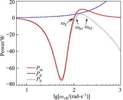
Fig. 2 Curves of averaged power
For any ��, if Pm(��) is equal to zero, then the frequency �� may be defined as the phase crossing frequency of the levitation system and denoted as ��c. For any ��, if Pb(��) is equal to zero, then it can be defined as the energy crossing frequency and denoted as ��bi (i=1, 2), which are shown in Fig. 2.
Considering the passivity of the bridge itself, the occurring of the vibration of bridge means the positive energy exportation of levitation system. Hence, if the self-excited vibration occurs, the frequency of vibration should be greater than ��c, regardless of how large the modal frequency and the modal damping of bridge are. With the similar analysis, we can conclude the vibration frequency should be larger than ��b1 and less than ��b2.
To avoid the remainder accumulated energy over the frequencies ranges [��b ��b2], increasing the power dissipated by the modal damping of bridge may be an effective solution. To explain it intuitively, the following two cases, ��B=0.01 and 0.02, are assumed, and the averaged accumulated powers are shown in Fig. 3.
According to Fig. 3, when the damping factor ��B is 0.02, for any ��, Pb(��) will be negative for any ��. Hence, the energy accumulated by the bridge will be less than zero, considering the passivity of the bridge itself, the vehicle-bridge interaction system will be stable on condition that the levitation system itself is stable. Whereas when the damping ratio ��k is equal to 0.01, the instability of interaction system may occur. Hence, we can conclude that the larger modal damping of bridge is beneficial for avoiding the self-excited vibration.

Fig. 3 Averaged accumulated powers with different damping factors
4 Sky-hooked damper
Although increasing the modal damping of bridge is beneficial for the stability of the vehicle-bridge interaction system. However, as we all known, the modal damping of bridge is tough to reshape except for the improvement of its material and technique. Considering the addition of a sky-hooked damper to the bridge increases the dissipated energy, it may be an effective solution to avoid the self-excited vibration.
4.1 Real sky-hooked damper to bridge
The sky-hooked damper, which is installed between the bridge and an inertial reference plane, is shown in Fig. 4. The damping coefficient of the sky-hooked damper is denoted as csky. When considering the application of sky-hooked damper, the vertical dynamic equation of the bridge is
 (21)
(21)
In light of Eq. (21), Eq. (6) may be rewritten as
 (22)
(22)
According to Eq. (22), it can be seen that the addition of a sky-hooked damper to the bridge enlarges the equivalent modal damping of bridge. If the equivalent modal damping factor is greater than 0.02, the vehicle-bridge interaction system will be stable, and the self-excited vibration may be avoided.

Fig. 4 Simplified vehicle-bridge interaction system with real sky-hooked damper
4.2 Virtual sky-hooked damper
Although the real sky-hooked damper is conductive for the stability of the interaction system, it is demanding to obtain an inertial reference plane for its installation. Besides, the addition of shy-hooked damper increases the construction cost and goes against the aesthetics of bridge. Considering the fact that the electromagnet itself is an excellent actuator that is capable of providing sufficiently large and fast force acting on the bridge to emulate the influence of the sky-hooked damper, it may be a brand new and effective solution for avoiding the self-excited vibration without any addition of hardware.
To emulate the force of the sky-hooked damper, the principle underlying the emulating the sky-hooked damper by the additional electromagnetic force of electromagnet should be determined. In light of Eq. (21), the force acting on the bridge due to the installation of real sky-hooked damper is
 (23)
(23)
Furthermore, according to Eq. (14), the electromagnetic force is proportional to the current flowing though the electromagnet around the equilibrium point. Therefore, the force acting on the bridge may be emulated by adding an additional current 
 to the original current i(t).
In light of Eq. (13), to accelerating the response of electromagnet to the current instruction ie(t), the inner loop with current feedback has been adopted. Considering the rapidity of response to the current instruction, the time delay between the current instruction ie(t) and the actual current i(t) may be neglected when the frequency of current instruction ie(t) is no more than 20 Hz. Then the force acting on the bridge by a real sky-hooked damper may be emulated by adding an additional current instruction isky(t) to the current instruction ie(t). This is to say,
 (24)
(24)
Furthermore, the control voltage of electromagnet should be updated as
 (25)
(25)
In light of Eq. (23), the calculation of the force acting on the bridge by the real sky-hooked damper relies on the vertical velocity of bridge. However, the vertical velocity is hard to be measured directly due to the lack of suitable sensors. Therefore, the real time velocity estimation is essential to enable the successful application of the virtual sky-hooked damper.
In a real maglev system, two real-time signals, including the levitation gap ��(t), which is measured by an eddy current gap sensor, and the acceleration of the electromagnet aE(t), which is detected by an accelerometer, are available. Using the aforementioned two signals, the vertical velocity of bridge may be estimated out by the following estimator.
 (26)
(26)
 (27)
(27)
where the variable yB(t) is the estimated velocity of bridge. The estimator is always stable provided that ��1, ��2, ��3 and �� are all positive. In the case of ��1=0.01, ��2=0.02, ��3=0.04 and ��=1/4000, the estimator is capable of estimating the vertical velocity of the bridge whilst filtering out the direct bias mixed within the measured acceleration signal and the high-frequency noise of gap signal.
The block diagram of the closed loop system with velocity estimators and virtual sky-hooked damper is shown in Fig. 5, in which the block EM represents the dynamics of electromagnets.
5 Numerical simulation and experimental validation
The application of real sky-hooked damper to the bridge is an effective technique to solve the problem of self-excited vibration. However, the hardware structure of sky-hooked damper is complicated and the cost of construction is prohibitive. Considering the fact that the electromagnets are excellent actuators that are capable of providing sufficiently large forces acting on the bridge to emulate the force of the sky-hooked damper, it may be a brand new method to solve the issues without any addition of hardware, so that the verification of virtual sky-hooked damper is significant.
5.1 Numerical validation of virtual sky-hooked damper
In the subsection, the parameters of interaction system are listed as following. ��B=0.01, ��B=100, kp=4700, ki=400, kd=40, kc=40, ka=0.4. These parameters are from the CMS04 maglev system of China.
To obtain creditable conclusions, the maglev engineering conditions should be simulated at great length. The eddy gap sensor is sensitive to the magnetic field generated by the electromagnets and pulling motors. Besides, the direct component of the acceleration transducer is not absolutely zero. In this subsection, the reasonable amount of noise is applied to the gap sensors. Compared to the maximum amplitude of signals, the corresponding noise is up to about 0.2%. For the acceleration signals, the DC component is set as 0.08g.

Fig. 5 Block diagram of levitation system with virtual sky-hooked damper
Before the virtual sky-hooked damper is activated when t<3 s, the energy flowing into bridge from the levitation systems is greater than the energy dissipated by the modal damping of bridge, so that the reminder energy is accumulated continuously by bridge, which leads to the growth of vibration with the passage of time and shown in Fig. 6(a). To simulate the limit cycle observed in maglev engineering, a hard nonlinear damping of bridge is assumed and set as
 Here,
Here, 
 . At t=3.5 s, the self-oscillatory with constant vibration amplitude appears. In light of Fig. 6(a), the maximum fluctuation of the levitation gap is 2.1 mm, which degrades the ride comfort of the vehicle. Furthermore, the fluctuation of the current is up to 14 A, as shown in Fig. 6(c). The fluctuation of current impacts the power source violently, which should be considered carefully to avoid its collapse.
In light of Fig. 6(d), it can be seen that the difference between the actual vertical velocity of the bridge  and its estimated value
  is unacceptable when t<2 s, which is due to the transient response of the velocity estimator, especially the existence of the direct component of acceleration signals. When the transient response dies out, the high correspondence between the actual value and estimated value is hold and shown in Fig. 6(e).
To show the validity of the virtual sky-hooked damper, the virtual sky-hooked damper is activated at t= 4 s. Due to the activation of the virtual sky-hooked damper, the amplitude of the vibration is quickly attenuated, and the self-excited vibration disappears finally. We conclude that the virtual sky-hooked damper is useful for the stability of the vehicle-bridge interaction system.
In light of Fig. 6(f), the maximum value of additional current instruction isky(t) is about 0.5 A. Compared with the amplitude of control current i(t), the amplitude of additional current instruction isky(t) is negligible. In this sense, the influence of additional current instruction on the stability of the levitation system itself is tiny.
In this work, the influences of the time delay between the additional current instruction isky(t) and the increment of actual current due to its addition is not analyzed.To further verify the validity of the virtual sky-hooked damper, the experimental validation should be carried out.
5.2 Experimental validation of virtual sky-hooked damper
The experiments were conducted in the CMS-04 low speed maglev vehicle, on the maintenance platform of the Tangshan maglev test line, as shown in Fig. 7. The control system under test included a PWM chopper, a levitation module and a Power PC based digital control system which was capable of executing complex levitation control and vibration control algorithms.
All the experimental data was acquired through the Ethernet based levitation monitoring network in the CMS-04 vehicle and a laptop based monitoring terminal; the data sampling rate was 200 samples per second. Figure 8 shows the result of the field test that was undertaken at allocation on the maintenance platform where the self-excited vibration occurred.

Fig. 6 Validation of virtual sky-hooked damper, which is activated at t=5 s:

Fig. 7 Field experiments on a full-scale maglev train at Tangshan maglev engineering base.
When t<19 s, the self-excited vibration occurs. It can be observed that the levitation gap, current and acceleration signals fluctuate violently. The vibration of electromagnet degrades the stability of the levitation control, decreases the ride comfort.
At t=19 s, the virtual sky-hooked damper was activated. After a more drastic and short regulation, the fluctuation of the levitation gap, current flowing through the electromagnet and its acceleration died way immediately, and the attenuation of the vibration was even more rapid than the result obtained in the simulation. The difference between the simulation and the experiment is most likely due to the minor differences between the real structure of vehicle-bridge interaction system and its simulation model. Anyway, we can conclude that the virtual sky-hooked damper is effective on the suppression of self-excited vibration with out any hardware addition.

Fig. 8 Verification of virtual sky-hooked damper, which is activated at t=5 s:
6 Conclusions
1) A minimum coupled model containing a flexible bridge and a single levitation unit is presented. Then, based on the above model, the principle underlying the self-excited vibration is explored.
2) The increment of modal damping can dissipate the accumulated energy by the bridge and the self-excited vibration may be avoided. To enlarge the equivalent modal damping of bridge, the sky-hooked damper is adopted.
3) Considering the fact that the electromagnet itself is an excellent actuator that is capable of providing sufficiently fast and large force acting on the bridge to emulate the effect of the sky-hooked damper, the technique of the virtual sky-hooked damper is proposed.
4) The principle underlying the virtual sky-hooked damper by electromagnet is explored and the vertical velocity of bridge is estimated. The results illustrating the improvement of stability are provided.
References
[1] LI Jin-hui, LI Jie, ZHANG Geng. A practical robust nonlinear controller for maglev levitation system [J]. Journal of Central South University of Technology, 2013, 20(11): 2991-3001.
[2] ZHOU D F, HANSEN C H, LI J, CHANG W S. Review of coupled vibration problems in EMS maglev vehicles [J]. Journal of Acoustics and Vibration, 2010, 15(1): 10-23.
[3] ZHOU D F, LI J, HANSEN C H. Suppression of stationary maglev vehicle-bridge coupled resonance using a tuned mass damper [J]. Journal of Vibration and Control, 2013, 19(2): 191-203.
[4] ALBERT T E, OLESZCZUK G, HANASOGE, ARAVIND M. Stable levitation control of magnetically suspended vehicles with structural flexibility [C]// 2008 American Control Conference, Washington, America: IEEE Computer Society, 2008: 4035-4040.
[5] ALBERT T E, OLESZCZUK G. On the influence of structural flexibility on feedback control system stability for EMS maglev vehicles [J]. Journal of Dynamic Systems, Measurement and Control, 2011, 133(5): 1-6.
[6] WANG H P, LI J. Vibration analysis of the maglev guideway with the moving load [J]. Journal of Sound and Vibration 2007, 305(4): 621-640.
[7] WANG H P, LI J, ZHANG K. Non-resonant response, bifurcation and oscillation suppression of a non-autonomous system with delayed position feedback control [J]. Nonlinear Dynamics, 2008, 51(3): 447-464.
[8] ZHANG Z Z, ZHANG Z Z. Hopf bifurcation of time-delayed feedback control for maglev system with flexible guideway [J]. Applied Mathematics and Computation 2013, 219(11): 6106-6112.
[9] WANG H P, LI J, ZHANG K. Sup-resonant response of a non-autonomous maglev system with delayed acceleration feedback control [J]. IEEE Transactions on Magnetics, 2008, 44(10): 2338- 2350.
[10] PANG S T, TSAO T C, BERGMAN L A. Active and pass damping of Euler-Bernoulli Beams and Their interactions [J]. Journal of Dynamic Systems, Measurement and Control, 1993, 115(3):
[11] LI H, GOODALL R M. Linear and non-linear skyhook damping control laws for active railway suspensions [J]. Control Engineering Practice, 1999, 7: 843-850.
[12] LI L, MENG G. The analysis of coupling vibration between maglev vehicle and steel bridge [J]. Journal of Vibration and Shock, 2006, 25(6): 46-75.
[13] HAN H S, YIM B Y, LEE N J, HUR Y C, KWON J G. Vibration analysis of a maglev vehicle using electromagnetic suspension [C]// Proceeding of International Conference on Electrical Machines and Systems. Seoul, Korea: IEEE Computer Society, 2007: 1963-1969.
[14] ZHOU D F, LI J, ZHANG K. An adaptive control method to suppress the maglev track-induced self-excited vibration [C]// 2011 International Conference on Consumer Electronics, Communications and Networks. Xianning, China: IEEE Computer Society, 2011: 4723-4727.
[15] ZHANG L L, ZHANG Z Z, HUANG L H. Double Hopf bifurcation of time-delayed feedback control for maglev system [J]. Nonlinear Dynamic, 2012, 69(3): 961-967.
[16] GUZMAN H. Current loops in a magnetic levitation system [J]. Journal of Innovative Computing, Information and Control 2009, 5(5): 1275-1283.
(Edited by DENG L��-xiang)
Foundation item: Projects(11302252, 11202230) supported by the National Natural Science Foundation of China
Received date: 2014-11-15; Accepted date: 2015-03-20
Corresponding author: LI Jin-hui, PhD; Tel: +86-731-84573387-8103; E-mail: li_jinhui@126.com

