Trans. Nonferrous Met. Soc. China 23(2013) 3540-3544
Effects of heat treatment on microstructure and microhardness of linear friction welded dissimilar Ti alloys
Chuan-chen ZHANG1,2, Tian-cang ZHANG1, Ya-juan JI1, Ji-hua HUANG2
1. AVIC Beijing Aeronautical Manufacturing Technology Research Institute, Beijing 100024, China;
2. School of Materials Science and Engineering, University of Science and Technology Beijing, Beijing 100083, China
Received 17 September 2012; accepted 15 October 2013
Abstract: A detailed investigation for the influence of post weld heat treatment (PWHT) on the microstructure of TC4 and TC17 dissimilar joints was analyzed. The fully transformed microstructure in the as-welded zone indicated that the peak temperature exceeded the ��-transus temperature at the weld interface during linear friction welding. TC4 side was mainly composed of martensite ���� phase with random distribution and it was single �� for that of TC17. In the thermomechanically affected zones of TC4 and TC17, the structure undergoes severe plastic deformation and re-orientation, yet without altering the phase fractions. After PWHT, in the weld zone of TC4 alloy, the phase transformation ����� ��+�� occurred and the acicular �� was coarsened, which resulted in a decrease in hardness. In the weld zone of TC17 alloy, fine �� phase precipitated at the grain boundary and within �� grains, which resulted in a sharp increase in hardness.
Key words: linear friction welding; Ti alloys; heat treatments; microstructure; microhardness
1 Introduction
Linear friction welding (LFW) is a solid-state joining process in which a stationary part is forced against a part that is reciprocating in a linear manner to generate frictional heat [1-3]. The heat, along with the force applied perpendicular to the weld interface, causes material at the interface to deform and plasticize [4,5]. During LFW, surface oxides and other impurities are removed from the friction interface [6-9].
Various researchers have used different Ti alloy material systems to reveal the nature of LFW joints. WANJARA and JAHAZI [10] investigated the microstructure of LFW processed Ti-6Al-4V. They concluded that the temperatures exceed the ��-transus temperature forming martensitic/acicular �� at the weld line (WL). DAYMOND and BONNER [11] and PREUSS et al [12] observed the LFW joints of Ti-64 and IMI550, respectively, which exhibited large tensile residual stresses with a significant hydrostatic tensile stress component in the weld region. These stresses are relieved after an optimized post-weld heat treatment (PWHT). DAYMOND and PREUSS [11] from their strain measurements in different crystallographic directions also indicated the presence of textured zones achieved through the process of grain reorientation during welding. MA et al [13] observed the formation mechanism of linear friction welded Ti-6Al-4V alloy joint based on the microstructure. They concluded that the dynamic recovery and recrystallization resulting from the severe plastic deformation and fast heating and cooling processes during linear friction welding account for the superfine ��+�� grains in the weld center. ROMERO et al [14] focused on the effect of the forging pressure on the microstructure of LFW processed Ti-6Al-4V joint. They found that a strong ��-Ti texture was generated in the weld line, which could be reduced by increasing the weld pressure. LI et al [15] and MA et al [16] investigated post-weld heat treatment on the microstructure and property of linear friction weld joints. They found that the post-weld heat treatment had an obvious influence on the microstructure and properties of LFW joints.
To date, most of the LFW development has been driven by the aero-engine industry��s desire to fabricate titanium alloy bladed disk, giving lower weight. LFW can also be used to join dissimilar alloys in order to employ the optimum alloys for the blade exposed to high cycle fatigue and high temperature and disk exposed to low cycle fatigue [17]. TC4 and TC17 Ti alloys were used widely for gas turbine compressor such as integrally bladed titanium alloy disks of compressor owing to good mechanical properties in the middle temperature range, high specific strength, and corrosion-resistant ability.
The present investigation focuses on characterizing the microstructural and mechanical property development due to LFW in dissimilar Ti alloys (TC4 and TC17). By investigating the microstructures of linear friction welded TC4 and TC17 joints, the present work aims to deepen our understanding of the linear friction weldability of TC4 and TC17 and to provide important information on LFW.
2 Experimental
Hot-rolled TC4 and ��-forged TC17 materials were received in bar form with a configuration of 20 mm in width (W), 75 mm in height (H) and 130 mm in length (L). The two specimens were installed as a butt joint, as shown in Fig. 1. The joining studies on the TC4 and TC17 alloys were carried out on a LFW machine with a 200 kN force capacity which was researched by Beijing Aeronautical Manufacturing Technology Research Institute, China. The key processing parameters involved in LFW were the amplitude of oscillation (3 mm), frequency of oscillation (40 Hz), the friction time (4 s) and friction force (80 MPa).
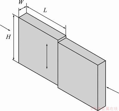
Fig. 1 Schematic diagram of LFW process
After welding, post-welded heat treatment of the joints was performed at 580 ��C and 655 ��C for 3 h. Then, the sectioning of joints was performed transverse to the weld interface, perpendicular to the plane of reciprocating linear motion. The cross-sections were polished and etched using Kroll��s reagent (100 mL H2O+2 mL HF+5 mL HNO3). The microstructure of the joints was observed by scanning electron microscopy. The microhardness across the as-welded and PWHT welded regions at the axial centreline was measured using a load of 1.96 N (200 g) on FM-700 Vickers microhardness tester with a built in microprocessor for automated determination of hardness values.
3 Results and discussion
Figure 2 shows the microstructures of TC4 and TC17 base metal. As shown in Fig. 2(a), the microstructure of TC4 consists of equiaxed �� grain (dark gray) and intergranular mixture of lamellar �� and �� grain. The microstructure of TC17 base metal has basket microstructure and consists of acicular �� and retained �� (Fig. 2(b)).
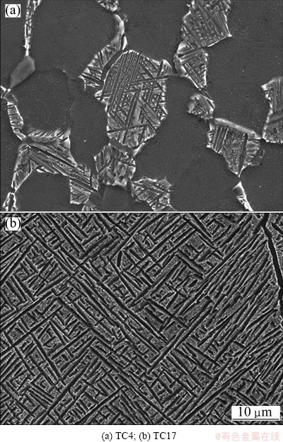
Fig. 2 Microstructures of base metal
An appreciable flash from all sides of the joint was observed, as illustrated in Fig. 3. The flash length was found to be larger in the direction of the oscillatory movement, as compared with that along the specimen width. The flash was composed of many ridges which were the result of the oscillating extrusion process during LFW.
3.1 Weld microstructure
During LFW, the combination of frictional heating and thermomechanical deformation resulted in a severe, yet localised, microstructural development. Generally, the weld could be classified into three microstructural zones [10]: the base metal (BM), the thermo- mechanically affected zone (TMAZ) and the weld zone (WZ), as shown in Fig. 4.
As shown in Fig. 4, the weld interface still exists and the WZ is divided into two distinct zones by the interface. The intergrowth grain formed at the interface, which resulted in forming a sound weld. Because the weld joint was formed by dissimilar Ti alloys, the microstructure and the mechanical property of the weld zone in the two-side interface are different.
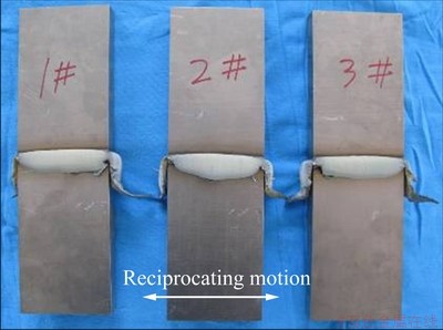
Fig. 3 Optical micrographs of joints at same process parameters

Fig. 4 LFW microstructural zone
The cross-sectional microstructures of the joint at different PWHT are shown in Fig. 5. Compared with the base metal, the microstructure in the weld zone was considerably different. A fully transformed superfine microstructure (��+��) was observed in the WZ (Fig. 5(a)), which indicates that the material in this region exceeded the ��-transus during linear friction welding. It is found that the microstructure of the weld zone of TC4 alloy mainly consists of martensite ���� phase with random distribution and it is single �� for that of TC17 alloy. Highly deformed �� and �� grains were formed along the deformation direction in TC4 and TC17 TMAZ, as shown in Figs. 5(b) and (c). But both sides of TMAZ retained the ��/�� phase fractions and some recrystallized �� can be seen, which suggests that this region did not exceed the ��-transus [17]. The formation of recrystallized �� could attribute to the low stable temperature for �� phase.
Figures 5(d)-(i) show the microstructure of the heat treated joints at different zones. After heat treatment at 580 ��C for 3 h, the phase transformation �������+�� occurred in the WZ of TC4 alloy, indicated by �� phase and the transformed �� matrix of the microstructure (Fig. 5(d)). In the WZ of TC17 alloys, fine �� phase precipitated at the grain boundaries and within the �� grains, which indicates that phase transformation �¡��� had occurred in this region. But not too much change has taken place in the weld zone, and only grain boundaries become clear for short-range diffusion of the alloying elements. The results showed that the heat treatment temperature supplied not enough activation energy for the decomposition of the metastable �� phase under this condition. After PWHT at 655 ��C for 3 h, the size of transformed �� and �� in the WZ of TC4 alloy was larger than that observed for PWHT at 580 ��C for the same duration (Fig. 5(g)). In TMAZ of TC4, the deformed �� precipitated superfine ��+�� and elongated �� grains coarsened at 580 ��C for 3 h (Fig. 5(e)). As shown in Fig. 5(h), at higher heat treatment temperature (655 ��C, 3 h), the deformed metastable �� phase transformed completely and the elongated �� varied slightly (Fig. 5(h)) compared with Figs. 5(b) and 5(e). In TMAZ of TC17, the deformed structure precipitated superfine �� and �� grains at 580 ��C for 3 h of heat treatment (Fig. 5(f)) and the precipitated �� grains were coarsened after 655 ��C for 3 h (Fig. 5(i)).
The observation indicates that in the as-welded zone, the dynamic recrystallization occurred during the welding process. On account of the rapid cooling after welding, the recrystallization was not sufficient and the transformed microstructure was refined. The dislocation was consumed partly and the dislocation density that remained was not high in the WZ. After heat treatments, the microstructure of the weld was coarsened, and the size of the transformed �� increased with increasing heat treatment temperature. These results suggest that temperature is one of the main reasons to influence the transformation structure.
3.2 Microhardness examination
The microhardness profile across the weld interface for the as-welded and PWHT processed joints is plotted in Fig. 6. In the TC4 alloy side, as shown in the left part of Fig. 6, the microhardness decreased from the weld interface to the BM of TC4. The hardness value of BM of TC4 did not show a significant variation as denoted by the small fluctuation in the hardness that was observed. After PWHT, the hardness value of the joint exhibited a reduction compared with the as-welded condition. The reduction in hardness was that the acicular martensite disappeared and the �� grain was coarsened. The BM microhardness after PWHT showed a small decrease.
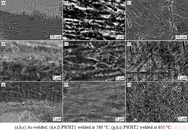
Fig. 5 SEM images of weld-lines (a,d,g), TMAZ of TC4 side (b,e,h) and TC17 side (c,f,i) of joints
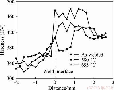
Fig. 6 Microhardness traces joints as-welded and PWHT
In the TC17 side, as shown in the right side of Fig. 6, the microhardness of the weld zone showed a big decrease compared with the BM of TC17. After PWHT, all samples exhibited higher hardness compared with the as-weld condition in the weld zone and the hardness of BM of TC17 did not show a significant variation. This increase in hardness was attributed to the fine �� particle precipitated at the grain boundaries and within the �� grains. Compared with the hardness in TC17 side after PWHT, the higher the heat treatment temperature, the lower the hardness. The main reason is that the precipitated �� resulted in a decrease in hardness.
4 Conclusions
1) The microstructure of the weld zone was mainly composed of martensite ���� phase with random distribution in TC4 alloy and it was single �� for that of TC17 alloy. TMAZ microstructure undergoes severe plastic deformation and re-orientation, yet without altering the phase fractions.
2) After PWHT, in TC4 alloy, the ���� martensite decomposed and the acicular �� become more distinctly and were coarsened, resulting in a decrease in hardness. Fine �� precipitates were found to form in the weld region in TC17 alloy, resulting in a sharp increase in hardness.
References
[1] BHAMJI I, PREUSS M, THREADGILL P L, ADDISON A C. Solid state joining of metals by linear friction welding: A literature review [J]. Materials Science Technology, 2011, 27(1): 2-12.
[2] LANG B, ZHANG T C, LI XH, GUO D L. Microstructural evolution of a TC11 titanium alloy during linear friction welding [J]. Journal Materials Science, 2010, 45(2): 6218-6224.
[3] MA T J, LI W Y, YANG S Y. Impact toughness and fracture analysis of linear friction welded Ti-6Al-4V alloy joints [J]. Materials and Design, 2009, 30(8): 2128-2132.
[4] MARY C, JAHAZI M. Multi-scale analysis of IN-718 microstructure evolution during linear friction welding [J]. Advanced Engineering Materials, 2008, 10(6): 573-578.
[5] VAIRIS A, FROST M. Modelling the linear friction welding of titanium blocks [J]. Materials Science and Engineering A, 2000, 292(1): 8-17.
[6] VAIRIS A, FROST M. High frequency linear friction welding of a titanium alloy [J]. Wear, 1998, 217(1): 117-131.
[7] MARY C, JAHAZI M. Linear friction welding of IN-718: Process optimization and microstructure evolution [J]. Advanced Materials Research, 2007, 15-17: 357-362.
[8] MA T J, LI W Y, XU Q Z, ZHANG Y, LI J L, YANG S Q, LIAO H L. Microstructure evolution and mechanical properties of linear friction welded 45 steel joint [J]. Advanced Engineering Materials, 2007, 9(8): 703-707.
[9] ROMERO J, ATTALLAH M M, PREUSS M, KARADGE M, BRAY S E. Effect of the forging pressure on the microstructure and residual stress development in Ti�C6Al�C4V linear friction welds [J]. Acta Materialia, 2009, 57(18): 5582-5592.
[10] WANJARA P, JAHAZI M. Linear friction welding of Ti�C6Al�C4V: Processing, microstructure, and mechanical- property inter- relationships [J]. Metallurgical and Materials Transactions A, 2005, 36(8): 2149-2164.
[11] DAYMOND M R, BONNER N W. Measurement of strain in a titanium linear friction weld by neutron diffraction [J]. Physica B, 2003, 325(1-4): 130-137.
[12] PREUSS M, da FONSECA J Q, STEUWER A, WANG L, WITHERS P J, BRAY S J. Residual stresses in linear friction welded IMI550 [J]. Journal of Neutron Research, 2004, 12(1): 165-173.
[13] MA Tie-jun, CHEN Tao, LI Wen-ya, WANG Shi-wei, YANG Si-qian. Formation mechanism of linear friction welded Ti-6Al-4V alloy joint based on the microstructure observation [J]. Materials Characterization, 2010, 62: 130-135.
[14] ROMERO J, ATTALLAH M M, PREUSS M, KARADGE M, BRAY S E. Effect of the forging pressure on the microstructure and residual stress development in Ti-6Al-4V linear friction welds [J]. Acta Materialia, 2009, 57(18): 5582-5592.
[15] LI W Y, WU H, MA T J, YANG C L, CHEN Z W. Influence of parent metal microstructure and post-weld heat treatment on microstructure and mechanical properties of linear friction welded Ti-6Al-4V joint [J]. Advanced Engineering Materials, 2010, DOI: 10.1002/adem.201100203.
[16] MA T J, LI W Y, ZHONG B, ZHANG Y, LI J L. Effect of post-weld heat treatment on microstructure and property of linear friction welded Ti17 titanium alloy joint [J]. Science and Technology of Welding and Joining, 2012, DOI: http://dx.doi.org/10.1179/ 1362171811Y.0000000079.
[17] KARADGE M, PREUSS M, LOVESS C, WITHERS P J, BRAY S. Texture development in Ti-6Al-4V linear friction welds [J]. Materials Science and Engineering A, 2007, 459(1-2): 182-191.
�ȴ����������ѺϽ�����Ħ������ͷ��֯����Ӳ�ȵ�Ӱ��
�Ŵ���1,2�������1�����Ǿ�1���Ƽ̻� 2
1. �����������칤���о���������100024��
2. �����Ƽ���ѧ ���Ͽ�ѧ�빤��ѧԺ������ 100083
ժ Ҫ���о������ȴ�����TC4��TC17�����ѺϽ�����Ħ������ͷ����֯��Ӱ�졣��̬�����º�����֯Ϊ��ȫ�ٽᾧ��֯����������Ħ�����ӹ����У�Ħ�������¶ȳ����������¶ȣ�����TC4�ຸ����֯��ҪΪ������������֯�ṹ�Ħ����࣬TC17�ຸ����֯��ҪΪ��һ�Ħ��ࡣTC4��TC17������Ӱ������֯Ϊ���صı�����֯���Ҿ������Եķ����ԣ����ڸ���������������δ�����仯���ȴ�����TC4�ຸ����֯�Ц���ת��Ϊ��״�Ħ�+���࣬�������ȴ����¶ȵ����ߣ���״����ֻ��������������ԣ������¸�������Ӳ���½���TC17�ຸ����֯�ȴ�����Ӿ���ͦ¾����ڲ�������ϸС�Ħ��࣬���¸�����Ӳ��������ߡ�
�ؼ��ʣ�����Ħ�������ѺϽ��ȴ���������֯����Ӳ��
(Edited by Hua YANG)
Corresponding author: Ji-hua HUANG; Tel: +86-10-62334859; E-mail: jihuahuang47@sina.com
DOI: 10.1016/S1003-6326(13)62898-8

