��Ӿ������ϵ绯ѧ��ԭ���Ʊ� ����ʯīϩ��֧�ű�Ĥ�缫����������
��Դ�ڿ����й���ɫ����ѧ��(Ӣ�İ�)2014���5��
�������ߣ��Ԫ�� �� �� �� ɭ ��ѧ�� ��Ф�� �� ��
����ҳ�룺1425 - 1433
�ؼ��ʣ���֧��ʯīϩ��Ĥ����������������Ӿ�������绯ѧ��ԭ������
Key words��free-standing graphene-like film; supercapacitor; electrophoretic deposition; electrochemical reduction; flexibility
ժ Ҫ��ͨ����Ӿ�����͵绯ѧ��ԭ����ϵķ����Ʊ����Ե�ʯīϩ��֧�ű�Ĥ�缫�����ȣ�ͨ��������ķ�����ʯī�������Ʊ�����ʯīϩ��Ĥ��Ȼ��ͨ��������ʯīϩ��Ĥ���е绯ѧ��ԭ���õ��������������ʯīϩ��Ĥ�缫���ϡ�ͨ��SEM��XRD��FT-IR�͵绯ѧ���Զ�ʯīϩ�ı�����ò���ṹ�͵������ܽ��б���������������Ʊ���ʯīϩ�����������ã���1 mol/L��������Һ�У�ѭ������ɨ��Ϊ10 mV/sʱ���ȵ���Ϊ254 F/g���������ܶ�Ϊ83.3 A/gʱ���ȵ����ܱ�����132 F/g��������ܶȿɴ�39.1 kW/kg�������ܶ�Ϊ11.8 W•h/kg����ŵ�ѭ��1000�κ����ܱ���97.02%��������ʯīϩ��Ĥ�缫���Ͼ��������ѭ���ȶ����ܡ�
Abstract: Electrophoretic deposition in conjunction with electrochemical reduction was used to make flexible free-standing graphene-like films. Firstly, graphene oxide (GO) film was deposited on graphite substrate by electrophoretic deposition method, and then reduced by subsequent electrochemical reduction of GO to obtain reduced GO (ERGO) film with high electrochemical performance. The morphology, structure and electrochemical performance of the prepared graphene-like film were confirmed by SEM, XRD and FT-IR. These unique materials were found to provide high specific capacitance and good cycling stability. The high specific capacitance of 254 F/g was obtained from cyclic voltammetry measurement at a scan rate of 10 mV/s. When the current density increased to 83.3 A/g, the specific capacitance values still remained 132 F/g. Meanwhile, the high powder density of 39.1 kW/kg was measured at energy density of 11.8 W•h/kg in 1 mol/L H2SO4 solution. Furthermore, at a constant scan rate of 50 mV/s, 97.02% of its capacitance was retained for 1000 cycles. These promising results were attributed to the unique assembly structure of graphene film and low contact resistance, which indicated their potential application to electrochemical capacitors.
Trans. Nonferrous Met. Soc. China 24(2014) 1425-1433
Yuan-yun DOU1, Min LUO1, Sen LIANG2, Xue-ling ZHANG1, Xiao-yi DING1, Bin LIANG1
1. Key Laboratory of Energy Resources and Chemical Engineering, Department of Chemical Science and Engineering, Ningxia University, Yinchuan 750021, China;
2. Key Laboratory of Ningxia for Photovoltaic Materials, Ningxia University, Yinchuan 750021, China
Received 17 June 2013; accepted 5 March 2014
Abstract: Electrophoretic deposition in conjunction with electrochemical reduction was used to make flexible free-standing graphene-like films. Firstly, graphene oxide (GO) film was deposited on graphite substrate by electrophoretic deposition method, and then reduced by subsequent electrochemical reduction of GO to obtain reduced GO (ERGO) film with high electrochemical performance. The morphology, structure and electrochemical performance of the prepared graphene-like film were confirmed by SEM, XRD and FT-IR. These unique materials were found to provide high specific capacitance and good cycling stability. The high specific capacitance of 254 F/g was obtained from cyclic voltammetry measurement at a scan rate of 10 mV/s. When the current density increased to 83.3 A/g, the specific capacitance values still remained 132 F/g. Meanwhile, the high powder density of 39.1 kW/kg was measured at energy density of 11.8 W��h/kg in 1 mol/L H2SO4 solution. Furthermore, at a constant scan rate of 50 mV/s, 97.02% of its capacitance was retained for 1000 cycles. These promising results were attributed to the unique assembly structure of graphene film and low contact resistance, which indicated their potential application to electrochemical capacitors.
Key words: free-standing graphene-like film; supercapacitor; electrophoretic deposition; electrochemical reduction; flexibility
1 Introduction
Supercapacitor has attracted great attention for a wide and growing range of applications due to its high energy density, rapid charging and discharging rate, long cycling life and low cost compared to conventional dielectric capacitors [1,2]. So far, various materials, such as carbonaceous material [3,4], metal oxide [5], conducting polymers [6] and their composites [7,8], have been used as supercapacitor electrode materials. Among these materials, carbon is the widely used electrode materials for supercapacitor, including activated carbon (AC) [9,10], mesoporous carbon (MC) [11], carbide derived carbon [12], carbon xerogel [13] and carbon nanotube [14]. Although these porous carbon materials have high specific surface area, but the low conductivity and high contact resistance between electrode and current collector limit the application in high powder density supercapacitors [15].
Graphene, with a two-dimensional one-atom-thick planar sheet of sp2 bonded carbon atoms, is the carbon material for potential application in electrochemical energy storage with various superior properties such as large specific surface area, high electrical conductivity and charge-carrier mobility, high mechanical strength and inherent flexibility [16-18].
Many methods, such as hydrothermal synthesis [19], vacuum filtration deposition [20], electrophoretic deposition [21], biotemplating method [22], have been carried out to prepare the grapheme-based carbon material with high effective surface areas, high electric conductivity and low contact resistance, which should be expected to exhibit better supercapacitor performance. ZHU et al [23] produced high surface areas carbon-based supercapacitors by activation of grapheme. MILLER et al [24] prepared vertically oriented graphene nanosheets directly on metal current collectors to minimize electronic and ionic resistances. YOO et al [25] fabricated the ultrathin supercapacitors by ��in-plane�� design to exploit the surface of each graphene layer for energy storage. However, synthesizing the graphene material with less agglomeration and manipulating the graphene nanosheets into controllable architectures film electrode were still challenges due to the hydrophobicity and staking interaction among graphene sheets.
It has been reported that assembly of GO sheets on a solid substrate was a good way to prevent the aggregation of GO after reduction [26]. Given that the difficulty of directly assembling the graphene electrode materials, an alternative strategy was proposed to firstly prepare the graphene oxide film electrode materials by electrophoretic deposition (EPD), and then electrochemically reduce the GO films to graphene-like films by removing the oxygen-contained groups (OCGs) with the recovery of conjugated structure. In the process of fabricating the electrode materials, EPD was seen as one of the economical and versatile processing techniques for depositing various types of functional films due to unique microstructures, complex shape and rapid production times [27], while electrochemical reduction has been developed to achieve the reduction of GO to graphene due to its fast and green nature [28]. Herein, a flexible self-standing graphene-like membrane electrode material with large capacitance, low contact resistance and good cycling stability was developed. The graphene-like materials were obtained by a two-step process. In the first step, negative charged GO nanosheets suspended in an organic liquid migrated toward a positive electrode to form a homogeneous film with unique microstructure and complex shape by electrophoretic deposition. In the second step, the GO films were reduced by electrochemical reduction method, after the removal of OCGs of GO by electrochemical reduction, some micro-channels in the graphene-like film were left, which can significantly permeate electrolyte to facilitate ion transport. The influences of electrophoretic deposition voltage and time on the electrochemical properties were investigated.
2 Experimental
2.1 Preparation of ERGO film electrode
2.1.1 Synthesis of GO
Graphene oxide was synthesized from graphite flakes (Sinopharm Chemical Reagent Co. Ltd., China) by a modified hummer��s method. Briefly, graphite (2 g) and NaNO3 (1 g) were mixed with H2SO4 (50 mL, 98%) in a 500 mL beaker. The mixture was stirred for 30 min within an ice bath. While maintaining stirring, KMnO4 (5 g) was dissolved to the suspension and the mixture was continuous stirred for 30 min. The ice bath was then removed, and the mixture was stirred at 35 ��C for 2 h. As the reaction progressed, the mixture gradually became pasty, and the color turned into brownish. Then 50 mL H2O was slowly added to the pasty. The reaction temperature was rapidly increased by adding the boiling water (100 mL), and the color of solution changed to yellow. At the end, 15 mL of 30% H2O2 was added to the mixture. The precipitate was washed with excess water for several times. Further purified solution could be achieved by repeating centrifugation for several times until neutral pH, the graphene oxide (GO) powder was collected after freeze drying for 2 d.
2.1.2 Electrophoretic deposition of graphene oxide film
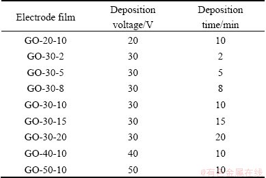
The as-obtained graphene oxide powers were transferred into alcohol and acetone mixed liquor to form stable graphene oxide colloids after ultrasonication with a concentration of 0.5 mg/mL. Electrophoretic deposition of graphene oxide was performed using a cell consisting of nickel plate as cathode and a graphite plate as anode. The two electrodes were placed parallel to each other and separated by 10 mm. The area of contact of each electrode with the GO slurry was 2 cm2. The samples used were listed in Table 1 together with electrophoretic deposition parameters (deposition voltage and deposition time), in which GO-30-5 signified that the deposition voltage was 30 V and the deposition time was 5 min, and the corresponding electrochemically reduced sample was designed as ERGO-30-5.
Table 1 Electrophoretic deposition parameters of electrode films
2.1.3 Electrochemical reduction of graphene-like film electrode
After deposition, the GO film on the graphite substrate was electrochemically reduced by cyclic voltammetry method from -1.2 to 0 V in 0.1 mol/L phosphate buffer solution (PBS, pH=6) at a scan rate of 10 mV/s. As-prepared ERGO film electrode was then rinsed with water and dried at room temperature for electrochemical characterization.
2.2 Characterization of materials
X-ray diffraction (XRD, D/MAX 2200P, Rigaku, Japan) analysis of the GO and ERGO films was carried out using the Cu K�� radiation (��=1.54184 nm). Scanning electron microscope (SEM, JSM-7500, JEOL, Japan) was employed for characterizing surface and cross section morphology. The FT-IR spectra (IRAffinity-1, SHIMADZU, Japan) were obtained with pure KBr as a background. The electrochemical performance was evaluated on a CHI660D workstation (CH Instruments, TX, USA) at ambient temperature. 1 mol/L H2SO4 was used as electrolytes, and CV, galvanostatic charge/ discharge and electrochemical impedance spectroscopy (EIS) were performed in a three-electrode configuration, with Pt foil as the counter electrode (CE), Ag/AgCl electrode as the reference electrode (RE) and ERGO film on graphite plate as the working electrode (WE).
The specific capacitance Cm of ERGO electrode film from CV could be calculated by
 (1)
(1)
where m is the mass of ERGO, ��V is the potential window; s is the scan rate, here s=10 mV/s; I is the instaneous charge current in given potential.
From the slope of galvanostatic charge/discharge curves, the specific capacitance (Cm), energy (E) and power densities (P) of ERGO were calculated according to the equations as follows:
 (2)
(2)
 (3)
(3)
 (4)
(4)
where I is the applied current; m is the mass of electrode; ��t is the charge time; ��E is the voltage range.
3 Results and discussion
3.1 Electrophoretic deposition of GO films on graphite substrate
The graphene oxide platelets were driven by electrical field during EPD and deposited on the graphite substrate. The effect of deposition voltage and deposition time on the mass per unit area is shown in Fig. 1. The deposition voltage has significant effect on the mass gain. When the voltage is below 30 V, the current density is low, leading to low deposition rate. The mass gain per unit area has a significant increase as the deposition voltage increases from 20 to 50 V (Fig. 1(a)). This fact is in agreement with the result reported by the previous study [29], which illustrated that the mass was increased with the increase of applied voltage, because the increase in applied voltage increased the rate of GO sheets migration, consequently, the mass of GO deposit. The mass gain of the GO films per unit area increases linearly with increasing deposition time from 5 to 10 min. However, the deposition time and thus the mass increase is limited by the form of a continuous GO film on the graphite substrate after 10 min deposition (Fig. 1(b)). This may be attributed to a gradual increase in the resistance of the graphite/GO film electrode due to the presence of oxygenated groups on the GO sheets surface which arouse insulating characteristics. It was reported that the current density during the EPD processing decreased rapidly with time [27]. The rapid decrease in the current density results in the decrease of the effective field between the electrodes, which is a cause of the decrease in deposition rate.
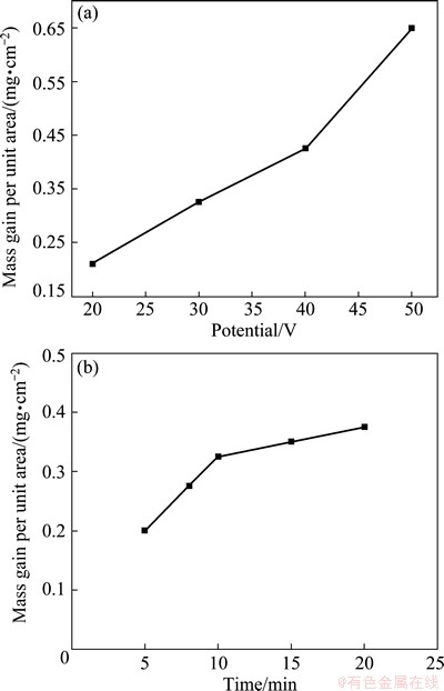
Fig. 1 Mass gain per unit area of GO film deposits as function of deposition voltage at deposition time of 10 min (a), and as function of deposition time at deposition voltage of 30 V (b)
Figure 2 shows the effect of deposition time on the film morphology. The bare graphite substrate has intense surface roughness with grooved surface morphology (Fig. 2(a)). During the deposition, a discontinuous GO film is formed on the surface of graphite substrate after 2 min (Fig. 2(b)). A relatively continual film is obtained when the deposition time is above 10 min (Fig. 2(c)). These results show an efficient electrophoretic deposited GO film on the anodic graphite electrode owing to a great amount of negatively charged OCGs on the GO nanosheets.
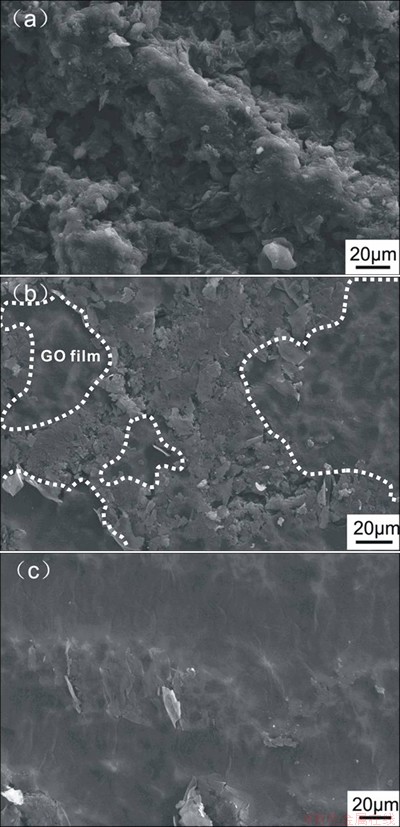
Fig. 2 SEM images of bare graphite substrate (a) and GO films deposited at time of 2 min (b) and 10 min (c) at 30 V deposition voltage
3.2 Electrochemical reduction of GO film electrode
Figure 3 shows the cyclic voltammograms of GO-30-10 film electrode in a PBS solution. The reduction voltage was changed from 0 to -1.2 V with respect to Ag/AgCl electrode at a scan rate of 10 mV/s. In order to define the location of the reduction peak, a control experiment with bare graphite substrate as the working electrode was carried out under the same conditions. The result is shown in Fig. 3, in which no reduction peak is found. The peaks from about -0.6 to -1.2 V can be attributed to the reduction of OCGs on the GO nanosheets. In the subsequent cycles, the reduction potential at about -0.6 V disappears, revealing that the reduced GO do not get oxidized in the potential range studied [30]. It is well known that there are various types of OCGs with different amount and location on the graphene oxide sheets, such as epoxy, carbonyl, carboxyl, hydroxyl, peroxy, aldehyde and lactone. It was reported that only the reduction of epoxides, aldehydes, and peroxides took place in the potential range of -0.9 to -1.5 V (vs Ag/AgCl) in neutral buffers. The rest of the groups were either nonreducible or would require more extreme conditions [31]. Therefore, a large anodic current peaks from -0.8 to -1.2V should be attributed to the reduction of these electrochemically reducible OCGs on the surface of GO film [32]. Moreover, from the first to the tenth cycle, the anodic current peak at -1.2 V becomes smaller and smaller, and the current peak has no significant difference from further cycle. In all cases, whatever at deposition voltage of 40 or 50 V, upon first scanning in a reduction from 0 to -1.2 V, a reducing wave is observed from -0.6 to -1.2 V and the electrochemical reduction finishes after 20 and 30 cycles, respectively. These demonstrate that the electrochemical reduction of surface-oxygenated species at GO film occurs quickly with an irreversible process.
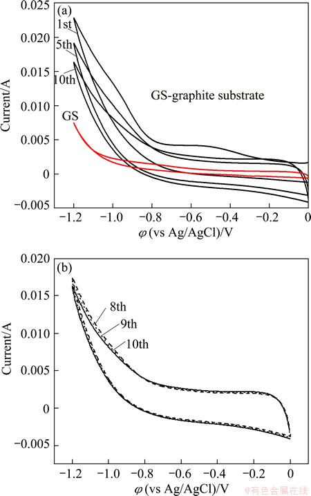
Fig. 3 Cyclic voltammogram of GO-30-10 film on graphite substrate and blank graphite substrate (red line) in PBS at scan rate of 10 mV/s
Figure 4 shows XRD patterns of GO(GO-30-10) and ERGO(ERGO-30-10) films. GO film exhibits a reflection with peak at 2�� of 10.9��, which corresponds to an interlayer distance of 0.81 nm. The XRD pattern of the electrochemical reduction ERGO film shows a broad reflection peak with the centre at 2�� of 22.7�� and a broad shoulder peak at about 2�� of 15�� with a lower intensity, which indicates that there are both sp2 domain from graphene and sp3 domain from graphene oxide.
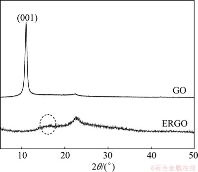
Fig. 4 XRD patterns of GO and ERGO film
The ERGO sample has more graphitic domains than oxidized domains. The peak broadening effect is due to the disordered stacking structure of graphene nanosheets.
In the IR spectra of GO and ERGO (Fig. 5), the bands at ~1730, ~1224, ~1053 cm-1 for GO correspond to the stretching band of C=O in carbonyl moieties, epoxy C��O and alkoxy C��O groups situates at the edges of GO, respectively, and the peaks at ~3440, ~1625, ~1352 cm-1 for ERGO correspond to the O��H stretch vibration, C=C stretch vibration and C��O stretch vibration, respectively [33]. FT-IR spectrum of the ERGO differs from that of the GO as evidences by the weakening of the peaks at ~1730, ~1224, ~1053 cm-1, respectively. The disappeared peaks of ERGO show that after the electrochemical reduction of GO, some unstable OCGs are removed, demonstrating that graphene can be achieved by electrochemical reduction approach.
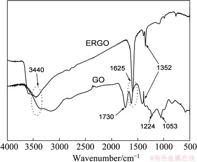
Fig. 5 FTIR spectra of GO and ERGO
BONANNI et al [31] reported that the amount of carboxylic groups in ERGO was increased compared with GO after electrochemical reduction. Carboxylic groups are overlapped with newly formed C=C stretch vibration corresponding to the recovery of conjugated structure after electrochemical reduction, which also enhances absorption intensity at ~1625 cm-1 in the FT-IR spectrum of ERGO [34].
The SEM image of the ERGO film surface (ERGO-30-10) reveals a typical wrinkled texture that is associated with the presence of flexible and ultrathin graphene sheets (Fig. 6(a)). These geometric wrinkling and rippling structures are caused by nanoscale interlocking of GO sheets, provided reduced surface energy and increased surface roughness and area [35]. If the deposition voltage is too low (20 V) or deposition time is too short (5 min), it is hard to take as-prepared ERGO film off the graphite substrate and the film is fragile. When the deposition voltage and time are higher than 30 V and 10 min, respectively, a high-quality flexible freestanding film is obtained (inset of Fig. 6(a)), which is possibly due to the formation of the continuous graphene film.
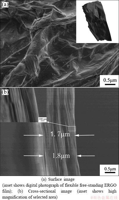
Fig. 6 SEM images of ERGO-30-10 film
Figure 6(b) shows the cross-sectional image of the ERGO film (ERGO-30-10). It shows that the thickness of ERGO film is 1.7-1.8 ��m, ERGO sheets are arranged intermittently with flat sheets, and form an interconnected film parallel to graphite substrate. Furthermore, from the insert image of Fig. 6(b), it shows that the ERGO film is composed by multilayer of ERGO sheets. This extraordinary structure with multilayer of ERGO sheets parallel to graphite substrate is contributed by the electrophoretic deposition combined with electrochemical reduction approach, and it is beneficial for the properties of supercapacitor devices.
3.3 Electrochemical characterizations of ERGO electrode
The electrochemical behavior of ERGO film electrode is evaluated with 3-electrode configuration in aqueous system in the potential range from -0.2 to 0.8 V (Figs. 7-10). Cyclic voltammograms (CVs) of the ERGO-30-10 and ERGO-40-10 film electrodes at 10 mV/s show nearly rectangular CV curves, indicating an idea capacitive behavior (Fig. 7). The ERGO-20-10 and ERGO-50-10 film electrodes present smaller current responses and narrower loop, which is typical of a higher resistive electrode. Apart from this, there is a pair of redox peak in the CV curves, which should be attributed to the reaction of quinine/hydroquinone groups and extra pseudocapacitive effects as follows [36,37]:
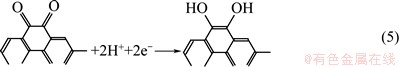

Fig. 7 Cyclic voltammograms of ERGO film electrodes made from different applied voltage at scan rate of 10 mV/s
In the CV curves of ERGO-50-10 film electrode, the anodic and cathodic peaks of HQ are observed at 440 and 190 mV, respectively. The peak potential separation (��EP) is about 250 mV, which indicates that hydroquinone (HQ) exhibits an irreversible electro- chemical behavior. ERGO-30-10 and ERGO-40-10 have similar redox peak location with anode peak at 0.41 V and cathode peak at 0.38V, leading to dramatically decreased ��EP of 30 mV for HQ. These results demonstrate that the over-potential of HQ at ERGO-30-10 and ERGO-40-10 film electrode is remarkably lowered and the electron transfer rate is much improved.
Figure 8 shows the specific capacitance as a function of scan rate for these four kinds of film electrodes. The specific capacitance of these three kinds of film electrodes decreases with increasing scan rate. Specific capacitances for ERGO-20-10, ERGO-30-10, ERGO-40-10 and ERGO-50-10 film electrodes are 146, 254, 186 and 153 F/g at scan rate of 10 mV/s, respectively. When the scan rate is 100 mV/s, the retention ratio of the four film electrodes is 75%, 74%, 76% and 55%, respectively. The higher specific capacitance and retention ratio for ERGO-30-10 are obviously assigned to the high effective surface areas and reduction of oxygen groups. As the deposition voltage increases, the deposited mass per unit area on the graphite substrate is increased, thus leading to the thicker film or more compact film electrode. The OCGs are more difficulty to be reduced completely from the thicker film or more compact ERGO film electrode by subsequent electrochemical reduction. Therefore, after electrochemical reduction, the remaining OCGs in the as-prepared ERGO film increase. The OCGs on the graphene surface are able to participate in faradic redox reaction. This is indicative of more preset capacitor and lower electron transfer rate in the ERGO-50-10 sample, leading to a dramatically reduction of specific capacitances at 100 mV/s. The highest retention ratio of ERGO-40-10 film electrode shows that the excellent affinity with water promotes the penetration of aqueous electrolyte. Figure 9 shows cyclic voltammograms (CVs) of the ERGO-30-10 film with various scan rates in the range from -0.2 to 0.8 V.
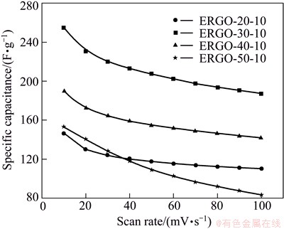
Fig. 8 Specific capacitance as function of scan rate
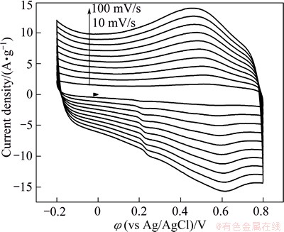
Fig. 9 Cyclic voltammograms of ERGO-30-10 film electrode at different scan rate
The increase of the peak currents with successive potential scans demonstrates that the deposition of conducting graphene on the graphite has been indeed achieved [38].
The relationship between the specific capacitance Cm and the deposition time at the deposition voltage of 30 V is shown in Fig. 10. The maximum value of specific capacitance is obtained for ERGO-30-10 electrode film. This can be explained by the fact that in shorter time the amount of evolved GO film accumulating on the anode is less, which can not form the continuous film. When deposition time is less than 10 min, the conversation from disconnection film to the integral film makes the increase of specific capacitance. However, prolonging the deposition time increases the thickness of the deposit film, which delays the efficient reduction, leading to low electric conductivity and high contact resistance. Thus, it is concluded that high performance of electrocapacitive ERGO electrode film can be formed at deposition voltage of 30 V and deposition time of 10 min.
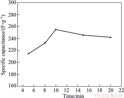
Fig. 10 Specific capacitance Cm of ERGO film electrode as function of deposition time at deposition voltage of 30 V in 1 mol/L H2SO4
Figure 11 shows the galvanostatic charge-discharge curves of ERGO-30-10 film electrode. The symmetric charge-discharge curves are linear in the total range of potential with constant slopes, showing nearly perfect capacitive behavior. No IR drop is detected even at higher discharge current density of 8 A/g, indicating a very low contact resistance.
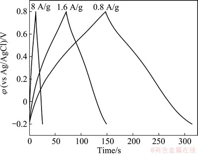
Fig. 11 Charge�Cdischarge curves at different current densities: 0.8, 1.6 and 8 A/g for ERGO-30-10 film electrode
The specific capacitances as a function of current density are shown in Fig. 12. The Cm of ERGO is calculated to be 254 F/g at a current density of 0.8 A/g. This value gradually decreases with the increase of current density, and stabilizes at 132 F/g when the current density increases to 83.3 A/g without a significant decrease of the charge-discharge cycling. The higher energy (11.8 W��h/kg) and powder density (39.1 kW/kg) is ascribed to the unique microstructure of EPD film with randomly stacking graphene nanosheets enhancing the microspores in the graphene film electrode surface.
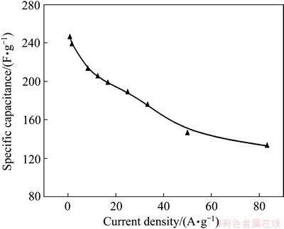
Fig. 12 Specific capacitance as function of current density
The specific capacitance of ERGO film is larger than those of GO reduced by electrochemical reduction approach [39], due to the high conductivity (without any binder) and extraordinary stacking structure with multilayer of ERGO sheets parallel to graphite substrate. PENG et al [40] reported that the specific capacitance of ERGO was only 128 F/g. This may be due to the low adhesion between GO film and substrate by casting method.
The cycle life of the supercapacitor electrode is an important factor for practical application. Figure 13 shows the variation of specific capacitance of ERGO-30-10 supercapacitor electrode at a constant scan rate of 50 mV/s in 1 mol/L H2SO4 solution for 1000 continuous cycles. It shows only 2.98% drop in the initial specific capacitance and remains at 213.8 F/g after 1000 cycles. This illustrates that the ERGO-based supercapacitor electrode has good stability and high specific capacitance.
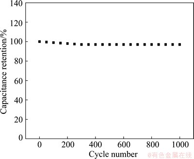
Fig. 13 Cycle life of ERGO-30-10 film electrode at constant scan rate of 50 mV/s
4 Conclusions
1) An easy and efficient electrophoretic deposition coupled with electrochemical reduction approach for synthesizing flexible free-standing ERGO film electrode material was developed.
2) The wrinkling and rippling structures with multilayer of graphene sheets parallel to graphite substrate existed in the ERGO film.
3) After electrochemical reduction, some unstable OCGs in GO film disappeared, hence the conductivity and capacitive properties of ERGO film were improved. High specific capacitance of 254 F/g was achieved from CV at a scan rate of 10 mV/s; even at high scan rate of 100 mV/s, the specific capacitance values still reached 205 F/g.
4) Application of this technique allows the preservation of GO microstructure in the graphene-like membrane electrode materials, making it possible to be applied in biosensor and energy storage field.
References
[1] CONWAY B E. Electrochemical supercapacitors. Scientific fundamentals and technological applications [M]. New York: Plenum Press, 1999.
[2] DUNN B, KAMATH H, TARASCON J M. Electrical energy storage for the grid: A battery of choices [J]. Science, 2011, 334: 928-935.
[3] INAGAKI M, KONNO H, TANAIKE O. Carbon materials for electrochemical capacitors [J]. Journal of Power Sources, 2010, 195(24): 7880-7903.
[4] FRACKOWIAK E. Carbon materials for supercapacitor application [J]. Physical Chemistry Chemical Physics, 2007, 9(15): 1774-1785.
[5] LIU K Y, ZHANG Y, ZHANG W, ZHENG H, SU G. Charge- discharge process of MnO2 supercapacitor [J]. Transactions of Nonferrous Metals Society of China, 2007, 17(3): 649-653.
[6] ZHANG L L, ZHAO S, TIAN X N, ZHAO X S. Layered graphene oxide nanostructures with sandwiched conducting polymers as supercapacitor electrodes [J]. Langmuir, 2010, 26(22): 17624-17628.
[7] WANG X F, RUAN D B, YOU Z. Application of spherical Ni(OH)2/CNTs composite electrode in asymmetric supercapacitor [J]. Transactions of Nonferrous Metals Society of China, 2006, 16(5): 1129-1134.
[8] ZHANG K, ZHANG L L, ZHAO X S, WU J. Graphene/polyaniline nanoriber composites as supercapacitor electrodes [J]. Chemistry of Materials, 2010, 22(4): 1392-1401.
[9] NANDHINI R, MINI P A, AVINASH B, NAIR S V, SUBRAMANIAN K R V. Supercapacitor electrodes using nanoscale activated carbon from graphite by ball milling [J]. Materials Letters, 2012, 87(15): 165-168.
[10] ZHOU S Y, LI X H, WANG Z X, GUO H J, PENG W J. Effect of activated carbon and electrolyte on properties of supercapacitor [J]. Transactions of Nonferrous Metals Society of China, 2007, 17(6): 1328-1333.
[11] LEI Z, CHRISTOV N, ZHAO X S. Intercalation of mesoporous carbon spheres between reduced graphene oxide sheets for preparing high-rate supercapacitor electrodes [J]. Energy & Environmental Science, 2011, 4(5): 1866-1873.
[12] GOGOTSI Y, NIKITIN A, YE H H, ZHOU W, FISCHER J E, BO Y, FOLEY H C, BARSOUM M W. Nanoporous carbide-derived carbon with tunable pore size [J]. Nature Materials, 2003, 2(9): 591-594.
[13] CHANG Y M, WU C Y, WU P W. Synthesis of large surface area carbon xerogels for electrochemical double layer capacitors [J]. Journal of Power Sources, 2013, 223: 147-154.
[14] IZADI-NAJAFABADI A, YASUDA S, KOBASHI K, YAMADA T, FUTABA D N, HATORI H, YUMURA M, IIJIMA S, HATA K. Extracting the full potential of single-walled carbon nanotubes as durable supercapacitor electrodes operable at 4 V with high power and energy density [J]. Advanced Materials, 2010, 22(35): E235- E241.
[15] WANG Y, SHI Z Q, HUANG Y, MA Y F, WANG C Y, CHEN M M, CHEN Y S. Supercapacitor devices based on graphene materials [J]. Journal of Physical Chemistry C, 2009, 113(30): 13103-13107.
[16] GUO S J, DONG S J. Graphene nanosheet: Synthesis, molecular engineering, thin film, hybrids, and energy and analytical applications [J]. Chemical Society Reviews, 2011, 40(5): 2644-2672.
[17] PUMERA M. Graphene-based nanomaterials for energy storage [J]. Energy & Environmental Science, 2011, 4(3): 668-674.
[18] SUN Y Q, WU Q O, SHI G Q. Graphene based new energy materials [J]. Energy & Environmental Science, 2011, 4(4): 1113-1132.
[19] XU Y X, SHENG K X, LI C, SHI G Q. Self-assembled graphene hydrogel via a one-step hydrothermal process [J]. ACS Nano, 2010, 4(7): 4324-4330.
[20] ZHANG S, LI Y, PAN N. Graphene based supercapacitor fabricated by vacuum filtration deposition [J]. Journal of Power Sources, 2012, 206(15): 476-482.
[21] YAO C, XIONG Z, PENG Y, YANWEI M. Electrophoretic deposition of graphene nanosheets on nickel foams for electrochemical capacitors [J]. Journal of Power Sources, 2010, 195(9): 3031-3035.
[22] WENG Z, SU Y, WANG D W, LI F, DU J, CHENG H M. Graphene-cellulose paper flexible supercapacitors [J]. Advanced Energy Materials, 2011, 1(5): 917-922.
[23] ZHU Y W, MURALI S, STOLLER M D, GANESH K J, CAI W W, FERREIRA P J, PIRKLE A, WALLACE R M, CYCHOSZ K A, THOMMES M, SU DONG, STACH E A, RUOFF R S. Carbon-based supercapacitors produced by activation of graphene [J]. Science, 2011, 332(6037): 1537-1541.
[24] MILLER J R, OUTLAW R A, HOLLOWAY B C. Graphene double-layer capacitor with ac line-filtering performance [J]. Science, 2010, 329(5999): 1637-1639.
[25] YOO J J, BALAKRISHNAN K, HUANG J S, MEUNIER V, SUMPTER B G, SRIVASTAVA A, CONWAY M, REDDY A L M, YU J, VAJTAI R, AJAYAN P M. Ultrathin planar graphene supercapacitors [J]. Nano Letters, 2011, 11(4): 1423-1427.
[26] WANG Z, ZHOU X, ZHANG J, BOEY F, ZHANG H. Direct electrochemical reduction of single-layer graphene oxide and subsequent functionalization with glucose oxidase [J]. Journal of Physical Chemistry C, 2009, 113: 14071-14075.
[27] KAYA C, KAYA F, SU B, THOMAS B, BOCCACCINI A R. Structural and functional thick ceramic coatings by electrophoretic deposition [J]. Surface and Coatings Technology, 2005, 191(2-3): 303-310.
[28] PEI S, CHENG H M. The reduction of graphene oxide [J]. Carbon, 2012, 50(9): 3210-3228.
[29] DJOSIC M S, MISKOVIC-STANKOVIC V B, KACAREVIC- POPOVIC Z M, JOKIC B M, BIBIC N, MITRIC M, MILONJIC S K, JANCIC-HEINEMANN R, STOJANOVIC J. Electrochemical synthesis of nanosized monetite powder and its electrophoretic deposition on titanium [J]. Colloids and Surfaces A��Physicochemical and Engineering Aspects, 2009, 341(1-3): 110-117.
[30] RAMESHA G K, SAMPATH S. Electrochemical reduction of oriented graphene oxide films: An in situ raman spectroelectrochemical study [J]. Journal of Physical Chemistry C, 2009, 113(19): 7985-7989.
[31] BONANNI A, AMBROSI A, PUMERA M. On oxygen-containing groups in chemically modified graphenes [J]. Chemistry��A European Journal, 2012, 18(15): 4541-4548.
[32] GUO H L, WANG X F, QIAN Q Y, WANG F B, XIA X H. A green approach to the synthesis of graphene nanosheets [J]. ACS Nano, 2009, 3(9): 2653-2659.
[33] WANG S, JIANG S P, WANG X. Microwave-assisted one-pot synthesis of metal/metal oxide nanoparticles on graphene and their electrochemical applications [J]. Electrochimica Acta, 2011, 56(9): 3338-3344.
[34] YANG Y, LIU T. Fabrication and characterization of graphene oxide/zinc oxide nanorods hybrid [J]. Applied Surface Science, 2011, 257(21): 8950-8954.
[35] YANG J, DENG S, LEI J, JU H, GUNASEKARAN S. Electrochemical synthesis of reduced graphene sheet-AuPd alloy nanoparticle composites for enzymatic biosensing [J]. Biosensors & Bioelectronics, 2011, 29(1): 159-166.
[36] WANG D W, LI F, ZHAO J, REN W, CHEN Z G, TAN J, WU Z S, GENTLE I, LU G Q, CHENG H M. Fabrication of graphene/polyaniline composite paper via in situ anodic electropolymerization for high-performance flexible electrode [J]. Acs Nano, 2009, 3(7): 1745-1752.
[37] ANDREAS H A, CONWAY B E. Examination of the double-layer capacitance of an high specific-area C-cloth electrode as titrated from acidic to alkaline pHs [J]. Electrochimica Acta, 2006, 51(28): 6510-6520.
[38] CHEN L, TANG Y, WANG K, LIU C, LUO S. Direct electrodeposition of reduced graphene oxide on glassy carbon electrode and its electrochemical application [J]. Electrochemistry Communications, 2011, 13(2): 133-137.
[39] YANG J, GUNASEKARAN S. Electrochemically reduced graphene oxide sheets for use in high performance supercapacitors [J]. Carbon, 2013, 51: 36-44.
[40] PENG X Y, LIU X X, DIAMOND D, LAU K T. Synthesis of electrochemically-reduced graphene oxide film with controllable size and thickness and its use in supercapacitor [J]. Carbon, 2011, 49(11): 3488-3496.
�Ԫ��1���� ��1���� ɭ2����ѧ��1����Ф��1���� ��1
1. ���Ĵ�ѧ ��ѧ����ѧԺ����Դ�����ص�ʵ���ң����� 750021��2. ���Ĵ�ѧ ��������ص�ʵ���ң����� 750021
ժ Ҫ��ͨ����Ӿ�����͵绯ѧ��ԭ����ϵķ����Ʊ����Ե�ʯīϩ��֧�ű�Ĥ�缫�����ȣ�ͨ��������ķ�����ʯī�������Ʊ�����ʯīϩ��Ĥ��Ȼ��ͨ��������ʯīϩ��Ĥ���е绯ѧ��ԭ���õ��������������ʯīϩ��Ĥ�缫���ϡ�ͨ��SEM��XRD��FT-IR�͵绯ѧ���Զ�ʯīϩ�ı�����ò���ṹ�͵������ܽ��б���������������Ʊ���ʯīϩ�����������ã���1 mol/L��������Һ�У�ѭ������ɨ��Ϊ10 mV/sʱ���ȵ���Ϊ254 F/g���������ܶ�Ϊ83.3 A/gʱ���ȵ����ܱ�����132 F/g��������ܶȿɴ�39.1 kW/kg�������ܶ�Ϊ11.8 W��h/kg����ŵ�ѭ��1000�κ����ܱ���97.02%��������ʯīϩ��Ĥ�缫���Ͼ��������ѭ���ȶ����ܡ�
�ؼ��ʣ���֧��ʯīϩ��Ĥ����������������Ӿ�������绯ѧ��ԭ������
(Edited by Chao WANG)
Foundation item: Projects (21361020, 21061012) supported by the National Natural Science Foundation of China; Project (NZ12156) supported by the Natural Science Foundation of Ningxia, China Project (N-09-13) supported by Project of State Key Laboratory of Catalysis, Dalian Institute of Chemical Physics of the Chinese Academy of Sciences
Corresponding author: Min LUO; Tel: +86-951-6892181; E-mail: luominjy@nxu.edu.cn
DOI: 10.1016/S1003-6326(14)63208-8

