J. Cent. South Univ. Technol. (2008) 15: 684-688
DOI: 10.1007/s11771-008-0127-3

Ultrasonic power features of wire bonding and thermosonic flip chip bonding in microelectronics packaging
LI Jun-hui(李军辉)1, 2, 3, HAN Lei(韩 雷)1, 2, ZHONG Jue(钟 掘)1, 2
(1. School of Mechanical and Electronical Engineering, Central South University, Changsha 410083, China;
2. Key Laboratory of Modern Complex Equipment Design and Extreme Manufacturing of Ministry of Education, Changsha 410083, China;
3. State Key Laboratory of Digital Manufacturing Equipment and Technology,
Huazhong University Science and Technology, Wuhan 430074, China)
Abstract: The driving voltage and current signals of piezoceramic transducer (PZT) were measured directly by designing circuits from ultrasonic generator and using a data acquisition software system. The input impedance and power of PZT were investigated by using root mean square (RMS) calculation. The vibration driven by high frequency was tested by laser Doppler vibrometer (PSV-400-M2). And the thermosonic bonding features were observed by scanning electron microscope (JSM-6360LV). The results show that the input power of bonding is lower than that of no load. The input impedance of bonding is greater than that of no load. Nonlinear phase, plastic flow and expansion period, and strengthening bonding process are shown in the impedance and power curves. The ultrasonic power is in direct proportion to the vibration displacement driven by the power, and greater displacements driven by high power (>5 W) result in welding failure phenomena, such as crack, break, and peeling off in wedge bonding. For thermosonic flip chip bonding, the high power decreases position precision of bonding or results in slippage and rotation phenomena of bumps. To improve reliability and precision of thermosonic bonding, the low ultrasonic power (about 1-5 W) should be chosen.
Key words: ultrasonic power; wedge bonding; thermosonic flip chip; input impedance; failure
1 Introduction
It has a long history that ultrasonic bonding technology has been applied to microelectronic packaging industry. At present, wire bonding is still commonly used as the bonding interconnection technique in the first level microelectronic package[1-2]. As ultrasonic bonding processes have unique advantages, in recent years, thermosonic flip chip technology is increasingly used in low pin counts applications, such as smart card, light-emitting diode (LED) and surface acoustic wave (SAW) filter in telecommunication applications[3]. This package technology is promising since it is clean, lead-free, adhesive-free and solder-less for area array interconnection. Thermosonic gold bonding provides strong metallurgical joining[4-5].
Three machine variables of load, power and time are often used to characterize bond formation during ultrasonic bonding. The final bond integrity is dependent on the three variables. A proper load allows the wedge movement to be transmitted to the wire and subsequently to the bond interface. The wire deformation during ultrasonic bonding is more sensitive to changes in power than to changes in machine load. The observed linear increase in groove spacing with power correlates with the wedge motion that also occurs with the increase of power. The tip-to-tip movement of the wedge is also dependent upon the fixturing of the wedge to the transducer horn. If the wedge is not suitably tightened, an unstable wave form will be transmitted to the wire. Fixturing is so critical that the replacement of a wedge to the same length with the same screw and the same tightness does not necessarily result in the same tip-to-tip displacement, with a variation of 20% being quite possible[6-8].
Ultrasonic energy driven by high frequency is a very important parameter. Frequency is one of important power parameters. Vibration and welding characteristics of complex vibration ultrasonic welding systems of 27 and 40 kHz were studied in Ref.[9]. The vibration characteristics of longitudinal-complex transverse vibration systems with multiple resonance frequencies of 350-980 kHz for ultrasonic wire bonding of IC (Integrated Circuit), LSI (Large Scale Integrated) or electronic devices were studied. The complex vibration systems can be applied to directly welding of semi- conductor tips (face-down bonding, flip-chip bonding)and packaging of electronic devices. The vibration distributions along ceramic and stainless steel welding tips were measured at up to 980 kHz. A high-frequency vibration system with a height of 20.7 mm and a mass of less than 15 g was obtained[10]. For welding systems with high frequencies of 55, 95, 190, 330 and 600 kHz, lots of bonding frequency characteristics, such as the welding temperature rise, the vibration locus of the welding tip, and the bonding strength, were investigated[11-14]. The current work has provided an important insight into the high frequency thermosonic bonding process.
The frequency of ultrasonic vibration is high, and the change of pressure is fast. During the thermosonic bonding process, the bonding between gold ball and substrate must experience many complex processes, such as contact, softening, slippage, and penetration[15]. Those processes must reflect the power of bonding process and the structure features. In this work, according to the relationship between the driving electric signal and power, the driving electric signals were measured by using a data collecting system, the vibration features driven by high frequency were tested by using PSV-400-M2 laser Doppler vibrometer, and the features of bonding were observed by using scanning electron microscope (JSM-6360LV). Based on the obtained images, the power and bonding characteristics were discussed. These are significant to enhance the reliability of ultrasonic bonding.
2 Experimental
2.1 Power data collecting system
Nickel plated on a copper plate was selected as a bonding surface for ultrasonic aluminum wedge bonding, and the major portion of this bonding program was performed using aluminum wire with diameter of 500 μm and LW500 wedge capillary on U3000 ultrasonic wedge bonder (made in Shenzhen, China) with frequency of 60 kHz.
According to the ultrasonic bonding, piezoceramic transducer (PZT) is driven by electric signal from ultrasonic generator. In the experiment, the driving voltage signal was measured directly by designing circuits from ultrasonic generator and using data acquisition software―Labview, and the current signal can be tested by using a resistance (R=9 Ω). The electric signals acquired by Labview may be stored in text file, and further process, such as analysis or display, can be performed with a Matlab program.
The characteristics of vibration parameters were tested by using PSV-400-M2 high frequency (1.5 MHz) laser Doppler vibrometer. The relationship between power and vibration velocity at different powers were tested.
2.2 Flip chip bed
To research power features of the thermosonic flip chip, the flip chip bonding bed was integrated by using a T/S-2100 ultrasonic wire bonder and a U3000 ultrasonic wedge bonder. The process parameter ranges of the assembly bed are: 60 kHz for frequency, 0-15 W for ultrasonic power, 20-500 ms for bonding time, 0.30-12 N for bonding force, and 25-400 ℃ for heating temperature.
The testing chips (from ASM Company) had 8-I/O connection gold bumps with diameter of 80 μm which were formed by using a ball bonder (see Fig.1).

Fig.1 Chip with 8 gold bumps
The characteristics of thermosonic bonding were investigated by using scanning electron microscope (JSM-6360LV).
3 Results and discussion
3.1 Input impedance and power
During ultrasonic bonding process, the input impedance of PZT is dynamic and nonlinear unless the transducer assembly is operated at its resonance. However, the concept of generalized impedance and power can be used to indicate the change of the input impedance and power of PZT. The input impedance of PZT is
 (1)
(1)
and the input power of PZT is
 (2)
(2)
where U0 and I0 represent the calculated root mean square (RMS), Uk and Ik are the sampling data in certain time; N is the sampling number, and N must be more than the data number of electric signal in a period. In the experiment, for the sampling frequency of 5×10⁵ /s, the data number of electric signal in a period is 18.
So, RMS calculation can be used to analyze the input impedance and power of PZT. The RMS calculation results by using software Matlab under no load and bonding are shown in Figs.2 and 3, respectively, where N=18.
Fig.2 shows that the input impedance of bonding is greater than that of no load. This is because the damping effects increase the impedance of transmitting energy system when the wire contacts the substrate during bonding process. Fig.3 shows that the input power of bonding is lower than that of no load. On the other hand, the start of curves of the input impedance and power is nonlinear phase, then decreases and remains smooth finally. The falling period of the power may indicate the plastic flow and bonding expansion of material. The penetration of bonding interface may be strengthened in later stable time. The features of input impedance and power gotten by voltage and current signals show the process during thermosonic bonding.
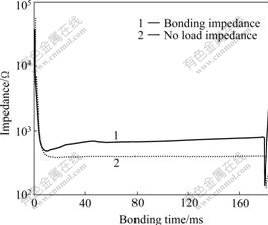
Fig.2 Input impedance curves of PZT in no load and bonding process at ultrasonic power of 3.5 W, bonding time of 150 ms and bonding force of 4.5 N
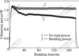
Fig.3 Power curves of PZT in no load and bonding process at ultrasonic power of 3.5 W, bonding time of 150 ms and bonding force of 4.5 N
3.2 Relationship between vibration and power
When power is 3.5 W, the utltrasonic vibration velocity at tool tip of flip chip is shown in Fig.4. Being similar to power, the start of vibration driven by the high frequency is nonlinear. When vibration remains stable, the peak value of vibration velocity (A) is 1.3 m/s. Fig.5 shows the vibration velocity curve from 11.30 to 11.5 ms, indicating that ultrasonic vibration is sinusoid, that is,
 (3)
(3)
where ω is the resonance angle frequency; φ is the phase angle. Fig.6 shows the result of fast Fourier transform (FFT) from Fig.4, indicating that resonance frequency is f=62.73 kHz. Thus,
ω=2πf≈3.94×10⁵ rad (4)
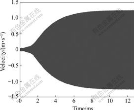
Fig.4 Vibration velocity at tool tip at ultrasonic power of 3.5 W

Fig.5 Vibration velocity curve at ultrasonic power of 3.5 W
Then the ultrasonic vibration displacement is
yt=A′sin(ωt+φ) (5)
The peak value of the vibration displacement is in direct proportion to that of vibration velocity.
Under different powers, the tested peak value of vibration velocity in Fig.7 shows that the power is in direct proportion to the vibration velocity. So, the power is in direct proportion to the vibration displacement driven by the power.
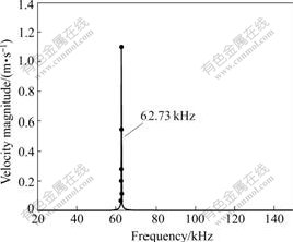
Fig.6 FFT result of vibration velocity at tool tip under condition of ultrasonic power of 3.5 W

Fig.7 Relationship between vibration velocity and power
3.3 Failure of greater power
When power is 8 W, the peak value of the vibration velocity is 2.50 m/s (see Fig.7), the peak value of vibration displacement is
 (6)
(6)
It indicates that the greater displacement driven by high power causes the decrease of characteristics of thermosonic bonding. Fig.8 shows that failures of bonding at high power (8.0 W) happen, such as crack, break, and peeling off in wedge bonding. However, when the power is 4.0 W, Fig.9 shows that ultrasonic bonding is very good.
Similary, Fig.10 shows that thermosonic flip chip bonding is better at power of 1.5 W during thermosonic flip chip bonding. However, Fig.11 indicates that the greater displacement driven by high power (6.0 W) causes the decrease of bump positioning precision of flip chip bonding or results in slippage and rotation phenomena of bumps.

Fig.8 Failure patterns at high power of 8.0 W: (a) Crack and break at top of bonding point; (b) Peeling off at root of joint

Fig.9 Successful wedge bonding at power of 4.0 W

Fig.10 Lift off characteristics of flip chip at power of 1.5 W, force of 4 N and time of 300 ms
To improve reliability and precision of ultrasonic bonding, the lower power (1-5 W) should be chosen.

Fig.11 Lift off characteristics of flip chip at high power of 6 W, force of 4 N and time of 300 ms
4 Conclusions
1) The input impedance and power curves of PZT analyzed by using RMS calculation show the nonlinear phase, plastic flow and expansion period, and strengthening process during the ultrasonic bonding. The input power of bonding is lower than that of no load. And the input impedance of bonding is greater than that of no load.
2) Ultrasonic vibration driven by high frequency sine signals is sinusoid, and the power is in direct proportion to vibration displacement driven by the power. The greater displacement driven by high power leads to welding failure phenomena, such as crack, break, and peeling off during wedge bonding. Similarily, the high power (>5 W) decreases the precision of bumps or results in slippage and rotation phenomena of bumps during thermosonic flip chip bonding. To obtain high- reliability and high-precision of bonding, low ultrasonic power (1-5 W) should be selected during thermosonic flip chip.
References
[1] LI J, HAN L, DUAN J, ZHONG J. Interface mechanism of ultrasonic flip chip bonding [J]. Applied Physics Letters, 2007, 90(24): 242902.
[2] LI Jun-hui, HAN Lei, ZHONG Jue. The characteristics of ultrasonic vibration transmission and coupling in bonding technology [C]// Proceedings of the 6th IEEE CPMT Conference on High Density Microsystem Design and Packaging and Component Failure Analysis. Shanghai, 2004: 311-315.
[3] ELGER G, HUTTER M, OPPERMANN H. Development of an assembly process and reliability investigations for flip-chip LEDs using the AuSn soldering [J]. Microsystem Technology, 2002, 7(5): 239-243.
[4] TAIZO T. Thermosonic flip chip bonding for low cost packaging [C]// 2002 International Symposium on Microelectronics. Denver, CO, United States, 2002: 360-365.
[5] LI J H, HAN L, ZHONG J. Interface structure of ultrasonic wedge bonding joints of Ni/Al [J]. Trans Nonferrous Met Soc China, 2005,15(4): 846-850.
[6] WINCHELL V H, BERG H M. Enhancing ultrasonic bond development [J]. IEEE Trans Hybrids, Manuf Technol, 1978, 3: 211-220.
[7] LI Jun-hui, HAN Lei, ZHONG Jue. Microstructural characteristics of Au/Al bonded interface [J]. Materials Characterization, 2007, 58(2): 103-107.
[8] DUAN Ji-an, LI Jun-hui, HAN Lei, ZHONG Jue. Interface features of ultrasonic flip chip bonding and reflow soldering in microelectronic packaging [J]. Surface and Interface Analysis, 2007, 39: 783-786.
[9] TSUJINO J, SANO T, OGATA H. Complex vibration ultrasonic welding systems with large area welding tips [J]. Ultrasonics, 2002, 40(1/8): 361-364.
[10] TSUJINO J, YOSHIHARA H, SANO T. High-frequency ultrasonic wire bonding systems [J]. Ultrasonics, 2000, 38(1/8): 77-80.
[11] LI Jun-hui, HAN Lei, ZHONG Jue. Observations on HRTEM features of thermosonic flip chip bonding interface [J]. Materials Chemistry and Physics, 2007, 106(2/3): 457-460.
[12] TSUJINO J, HONGOH M, TANAKA R. Ultrasonic plastic welding using fundamental and higher resonance frequencies [J]. Ultrasonics, 2002, 40(1/8): 375-378.
[13] TSUJINO J, KOICHI H. Ultrasonic wire bonding using high frequency 330, 600 kHz and complex vibration 190 kHz welding systems [J]. Ultrasonics, 1996, 34(4): 223-228.
[14] TSUJINO J, YOSHIHARA H, KAMIMOTO K. Welding characteristics and temperature rise of high frequency and complex vibration ultrasonic wire bonding [J]. Ultrasonics, 1998, 36(2): 59-65.
[15] KANG S F, WILLIAMS P M, MCLAREN T S. Studies of thermosonic bonding for flip-chip assembly [J]. Materials Chemistry and Physics, 1995, 42(3): 31-37.
(Edited by CHEN Wei-ping)
Foundation item: Project(50675227) supported by the National Natural Science Foundation of China; Project(07JJ3091) supported by Natural Science Foundation of Hunan Province, China; Project(2007001) supported by the State Key Laboratory of Digital Manufacturing Equipment and Technology; Project(2009CB724203) supported by the Major State Basic Research Development Program of China
Received date: 2008-01-18; Accepted date: 2008-03-25
Corresponding author: LI Jun-hui, PhD; Tel: +86-731-8877995; E-mail: lijunhui@mail.csu.edu.cn

