Trans. Nonferrous Met. Soc. China 26(2016) 1317?1325
Microstructure and interface thermal stability of C/Mo double-coated SiC fiber reinforced ��-TiAl matrix composites
Xian LUO, Chao LI, Yan-qing YANG, Hai-man XU, Xiao-yu LI, Shuai LIU, Peng-tao LI
State Key Laboratory of Solidification Processing, Northwestern Polytechnical University, Xi��an 710072, China
Received 5 May 2015; accepted 13 October 2015
Abstract: C/Mo duplex coating interfacially modified SiC fiber-reinforced g-TiAl matrix composite (SiCf/C/Mo/g-TiAl) was prepared by foil-fiber-foil method to investigate its interfacial modification effect. SiCf/C/TiAl composites were also prepared under the same processing condition for comparision. Both kinds of the composites were thermally exposed in vacuum at 800 and 900 ��C for different durations in order to study thermal stability of the interfacial zone. With the aids of scanning electron microscope (SEM) and energy dispersive spectrometer (EDS), the interfacial microstructures of the composites were investigated. The results reveal that, although adding the Mo coating, the interfacial reaction product of the SiCf/C/Mo/TiAl composite is the same with that of the SiCf/C/TiAl composite, which is TiC/Ti2AlC between the coating and the matrix. However, C/Mo duplex coating is more efficient in hindering interfacial reaction than C single coating at 900 ��C and below. In addition, a new layer of interfacial reaction product was found between Ti2AlC and the matrix after 900 ��C, 200 h thermal exposure, which is rich in V and close to the chemical composition of B2 phase.
Key words: Mo coating; TiAl alloy; SiC fiber; titanium matrix composite; interfacial reaction; thermal stability
1 Introduction
For high-temperature structural materials used in the fields of aeronautics and astronautics, high working temperature, high specific strength, high specific modulus and good oxidation resistance are crucial indices. Concerning these merits above, titanium aluminide intermetallics based on g-TiAl have drawn growing attention [1]. In order to have better mechanical properties, continuous fiber reinforced g-TiAl composites have been investigated by many researchers. Different fibers have been studied, such as Mo fiber, Ti fiber, Al2O3 fiber, TiNb fiber and CVD-SiC fiber [2-6]. Among them, only CVD-SiC fiber has the highest strength and modulus as well as the lowest density, so SiC fiber-reinforced g-TiAl matrix composites have been paid much attention to.
However, the TiAl-SiC system is not a chemical equilibrium system, as fiber/matrix interfacial reaction would occur to form reaction products during the fabrication and utilization of the composites at elevated temperatures. It was reported that the interfacial reaction layer of SiCf/Ti-43Al-9V composite is TiC/Ti2AlC/ (Ti,V)5(Si,Al)3 [7] and that of SiCf/Ti-48Al composite is TiC/Ti2AlC+Ti3AlC/(Ti,V)5(Si,Al)3 [8]. Generally, these brittle reaction products are detrimental to mechanical properties of the composites. One of the effective approaches of slowing down interfacial reaction is the application of a barrier coating. For example, C coating, B4C coating and Gd/GdBx duplex coating have been utilized [9,10]. Most of these coatings show good performance on retarding interfacial reaction to some extent. However, for a coating, it is not sufficient to consider only its ability to reduce interfacial reaction, moreover, its thermal expansion compatibility is also very important.
In this work, C/Mo duplex coating was chosen to modify the interfacial zone of the SiC fiber reinforced g-TiAl matrix composite (SiCf/g-TiAl). The idea is based on the following five considerations: 1) Coefficients of thermal expansion of the two coatings (C: 10��10-6 ��C-1,
Mo: (5.8-6.2)��10-6 ��C-1) [11] coordinate with that of SiC fiber (4.5��10-6 ��C-1) and the g-TiAl matrix ((12-14)��10-6 ��C-1) [12,13]; 2) Mo coating is a ductile coating, and can relieve thermal residual stresses; 3) Both of the coatings can reduce the interfacial reaction to some extent [14-17]; 4) Mo is a ��-stabilizer of titanium alloys. Once Mo atoms diffuse into TiAl matrix, the ductility of the matrix can be improved [18]; 5) C and Mo display good chemical stability with each other [19]. Our previous study of SiCf/C/Mo/Ti6Al4V composite also indicates that the two coatings can exist harmoniously below 900 ��C [16].
In order to evaluate the modification effect of C/Mo duplex coating on SiC fiber-reinforced g-TiAl matrix composite, single C coating with the same thickness was used for comparison. The interfacial microstructures and thermal stability of the SiCf/C/TiAl and SiCf/C/Mo/TiAl composites were comparatively studied under the same conditions.
2 Experimental
Ti-43Al-9V foils were utilized as matrix of the composites, which mainly contain �� phase as well as some ��2 and B2 phases. The initial microstructure of the foils was near lamellar structure [20]. The reinforcement SiC fiber (100-120 ��m in diameter) applied in this work was fabricated in China by chemical vapor deposition (CVD). The fiber has a tungsten core with a diameter of about 12 ��m. As shown in Fig. 1, two kinds of fiber coatings were prepared: 3.3 ��m-thick C coating, and 2 ��m-thick C coating + 1.3 ��m-thick Mo coating, respectively. C coating was deposited by chemical vapor deposition (CVD) while Mo coating was deposited by magnetron sputtering. The composites were fabricated by foil�Cfiber�Cfoil (FFF) method plus vacuum hot-pressing (VHP) under 1150 ��C, 150 MPa, 40 min.
After the preparation of the composites, part of the composites were cut into small pieces for thermal exposure treatment in vacuum. The vacuum thermal exposure conditions include (800 ��C, 100 h), (800 ��C, 200 h), (900 ��C, 100 h), (900 ��C, 200 h) and (900 ��C, 220 h), respectively. After that, metallographic specimens were prepared by conventional preparation methods of metallographic samples. Microstructures and chemical composition of the as-prepared and thermally- exposed composites were then studied by an SUPRA 55 SEM and an Oxford INCA EDS, respectively.
3 Results and discussion
3.1 Interfacial microstructure of as-prepared composites
Figures 2(a) and (b) show lower magnification micrographs of the as-prepared SiCf/C/TiAl and SiCf/C/Mo/TiAl composites, respectively. The black layer around the SiC fiber is C coating. The white layer in Fig. 2(b) next to the C coating is Mo coating. It can be seen that, although the two composites have the same total coating thicknesses (3.3 ��m) before processing, C/Mo duplex coating performs better on blocking the interfacial reaction than C single coating. This good result is reflected on the thickness of interfacical reaction zone. Figures 2(c) and (d) are higher magnification micrographs of the interfacial zones of the two composites. One can further see that the interfacial reaction layer in the SiCf/C/TiAl composite is distinctly thicker than that in the SiCf/C/Mo/TiAl composite.
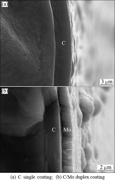
Fig. 1 Coating on surface of SiC fiber
The interfacial microstructure of SiCf/C/Ti-43Al- 9V composite fabricated by FFF method plus VHP under 1150 ��C, 150 MPa, 40 min has been investigated in Refs. [7] and [21]. Their results reveal that the interfacial phase sequence is SiC/C coating/TiC/Ti2AlC/g-TiAl from fiber side to the matrix. The only difference between ZHANG��s study [7,21] and this work is the thickness of C coating, which are 1 ��m and 3.3 ��m, respectively. The thicker the C coating is, the longer duration it can block the chemical reaction between SiC and the matrix. So, the interfacial phase sequence of the as-prepared SiCf/C/TiAl composite in this work should be also C coating/TiC/Ti2AlC.
In order to study the element distribution characteristics and interfacial phase sequence of the SiCf/C/Mo/TiAl composite, EDS line analysis as well as backscattered electron micrograph (SEM-BSE) was carried out in the interfacial zone of the as-prepared composite. The analyzed positions and corresponding results are shown in Fig. 3. According to the distribution and ratio of the elements, the interfacial zone can be divided into four layers, which are marked as 1 to 4 from fiber to the matrix in Fig. 3(b). Layers 1 and 2 are C coating and Mo coating with average thicknesses of 1.77 ��m and 1.20 ��m, respectively. Layers 3 and 4 are interfacial reaction zones, which mainly contain Ti, Al, V and C, almost without Si and Mo elements. In layer 3, the mole ratio of Ti:C is close to 1:1, so it can be inferred that layer 3 should be TiC. As for layer 4, it consists of Ti, Al, C and V. According to the ratio of the elements and the phase equilibrium between TiC and g-TiAl [22], the layer 4 may be Ti2AlC. Moreover, the difference between the SiCf/C/TiAl and the SiCf/C/Mo/TiAl composites is the existence of Mo coating. But according to the results above, Mo atoms hardly diffuse into the interfacial reaction layer. So, it is reasonable to believe that the interfacial product sequence of the SiCf/C/Mo/TiAl composite is TiC/Ti2AlC from Mo coating side to the matrix, which is the same with that of the SiCf/C/TiAl composite.
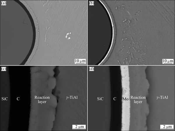
Fig. 2 Lower magnification images (a, b) and higher magnification images (c, d) of interface of as-prepared SiCf/C/TiAl (a, c) and SiCf/C/Mo/TiAl (b, d) composites

Fig. 3 Position of EDS line analysis on interface of as-prepared SiCf/C/Mo/TiAl composite (a) and element distribution curves along interfacial zone (b)
The reaction Ti+C��TiC is likely to happen first in TiAl-SiC system, which has been proved by many studies [7,9]. The initially formed TiC layer has characteristic of fine grains due to a high nucleation rate. With the concentration decrease of reagent, the nucleation rate also decreases [23]. Then, coarse TiC grain layer forms. Since the diffusion velocity of C atoms is higher than those of other atoms, the growth of interfacial reaction layer is mainly based on depletion of the matrix [17]. Al atoms do not join the first-step reaction, so the matrix next to TiC is Al-rich TiAl. Some studies imply that the enrichment of Al in TiAl matrix is beneficial for the formation of Ti-Al-C ternary compounds in order to reach the phase equilibrium [24]. Moreover, based on Ti-Al-C ternary phase diagram [22], Ti2AlC and Ti3AlC are the equilibrium phases for TiC/��-TiAl and TiC/��2-Ti3Al, respectively. Thus, Ti2AlC layer forms.
V and Mo atoms do not participate in the formation of TiC and Ti2AlC. Here, it is necessary to interpret the behaviors of V and Mo atoms during the interfacial reaction. As we know, VC and TiC are both of NaCl structure type (FCC), whose lattice constants are 0.4159 and 0.4329 nm, respectively. So, there is no doubt that V can substitute Ti to some degree. Moreover, TiC always has some Ti vacancies, which is also beneficial to the dissolution of V into TiC. In addition, Ti2AlC and V2AlC are also of the same Cr2AlC structure type (HCP), and the lattice constants are a=0.3056 nm, c=1.3623 nm and a=0.2909 nm, c=1.3127 nm, respectively [25]. So the same goes for V in Ti2AlC. As shown in Fig. 3(b) above, there exist some V in layer 3 (TiC layer) and layer 4 (Ti2AlC layer).
Figure 3(b) shows that Mo element does not diffuse into the interfacial reaction layer or into the TiAl matrix. While in our previous study of the SiC/C/Mo/Ti6Al4V composite, Mo coating had an affected zone of about 7.9 ��m in thickness [16]. The difference between the two composites can be explained in the light of different crystal structures. The Ti-6Al-4V matrix is solid solution with typical metallic bond. Mo element is an isomorphous one of b-Ti. So, although Mo atoms do not participate in the interfacial reaction, they can diffuse and dissolute into the matrix largely. While ��-TiAl matrix is intermetallics, whose bonding characteristics is a mixture of covalent bond and metallic bond. In addition, the diffusion of Mo atoms in TiAl is via the substitution of Ti [26], which is hard to occur. As a result, Mo atoms hardly diffuse and dissolve into the ��-TiAl matrix.
3.2 Composites after vacuum thermal exposure
In order to study thermal stability of the interface layers, vacuum thermal exposure treatments were carried out to the two kinds of composites. Figure 4 shows SEM-BSE photographs of the SiCf/C/TiAl and SiCf/C/ Mo/TiAl composites after 800 ��C, 100 h and 800 ��C, 200 h thermal exposure, respectively. Compared with the as-prepared composites, no obvious change occurs other than the thickening of interfacial reaction layers and the consumption of coatings. But it can be seen that the thickening of the reaction layer in the SiCf/C/TiAl composite is faster than that in the SiCf/C/Mo/TiAl composite. The similarity and dissimilarity between the two composites indicate a high stability of C single coating and C/Mo duplex coatings at 800 ��C, and C/Mo duplex coating is more efficient than C single coating.
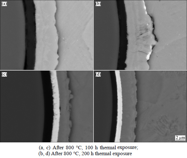
Fig. 4 Interfacial reaction zones of SiCf/C/TiAl (a, b) and SiCf/C/Mo/TiAl (c, d) composites
As the consumption of Ti atoms is larger than that of Al atoms in the interfacial reaction, the matrix adjacent to the interfacial reaction layer is Al-rich ��-TiAl in the as-prepared composites [21]. Figure 5 and Table 1 show the EDS composition analysis locations and corresponding results in the SiCf/C/TiAl and SiCf/C/ Mo/TiAl composites after 800 ��C, 200 h thermal exposure, respectively. It is seen that the matrix adjacent to the interfacial reaction layer of the SiCf/C/TiAl composite is still rich in Al, while in the SiCf/C/Mo/TiAl composites, this area has nearly reached homogenous composition with the rest of the matrix.
The matrix adjacent to the interfacial reaction layer is influenced by two processes. One is interfacial reaction, the other is annealing treatment. During the vacuum thermal exposure, the interfacial reaction continues, so the accumulation of Al atoms goes on. Meanwhile, this area also belongs to the matrix. Vacuum thermal exposure to the matrix means a composition homogenization process. If the accumulation velocity of Al atoms exceeds the velocity of composition homogenization process, this area remains rich in Al. If a balance has been achieved between the two velocities, this area would become homogeneous with the rest of the matrix. So, the difference between the two composites indicates that the accumulation velocity of Al atoms in the SiCf/C/Mo/TiAl composites is lower, which proves that C/Mo duplex coating is more efficient to hinder the interfacial reaction. This result is consistent with the conclusion we have got by comparing the thicknesses of the interfacial reaction layers in the as-prepared composites.

Fig. 5 EDS analysis position of matrix in composites after 800 ��C, 200 h thermal exposure
Table 1 EDS point analysis results of matrices corresponding to Fig. 5 (mole fraction, %)
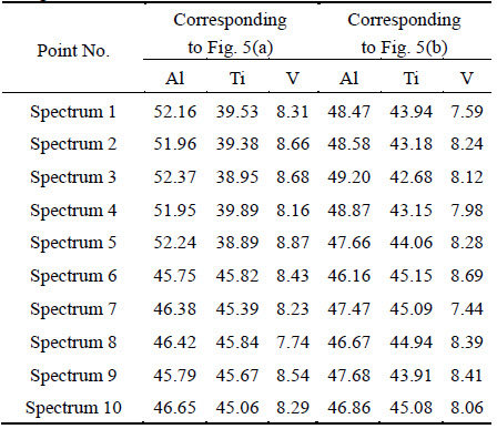
Figure 6 shows the interfacial zones of the SiCf/C/TiAl and SiCf/C/Mo/TiAl composites after 900 ��C, 100 h and 900 ��C, 200 h thermal exposure, respectively. Just like the situations at 800 ��C, the two interfacial layers show good stability, while C/Mo duplex coating still performs better. Especially after 900 ��C, 200 h thermal exposure, the C coating in the SiCf/C/TiAl composite has reduced from initial thickness of 3.3 ��m to less than 1 ��m, while the C coating in the SiCf/C/Mo/TiAl composite retains a thickness of 1.3 ��m, whose primary thickness is just 2 ��m.
In addition, it can be seen obviously from Figs. 6(b) and (e) that a new reaction layer appears in both of the composites after 900 ��C, 200 h thermal exposure. The difference is that, in the SiCf/C/TiAl composite, the new layer is approximately circle shape (shown in Fig. 6(c)), while in the SiCf/C/Mo/TiAl composites, it shows a sawtooth profile (shown in Fig. 6(f)). In order to verify the new phase, EDS line analysis as well as SEM-BSE imaging was carried out in the interfacial zone, as shown in Fig. 7. In comparison with the as-prepared composites, the layers 3 and 4 are still TiC and Ti2AlC, respectively, which are speculated by the EDS results. The diffusion of Mo atoms is still very limited, which can be proved by the EDS results in Fig. 7(d) and Spectrum 1 in Table 2.
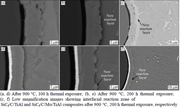
Fig. 6 Interfacial reaction zones of SiCf/C/TiAl (a, b, c) and SiCf/C/Mo/TiAl composites (d, e, f)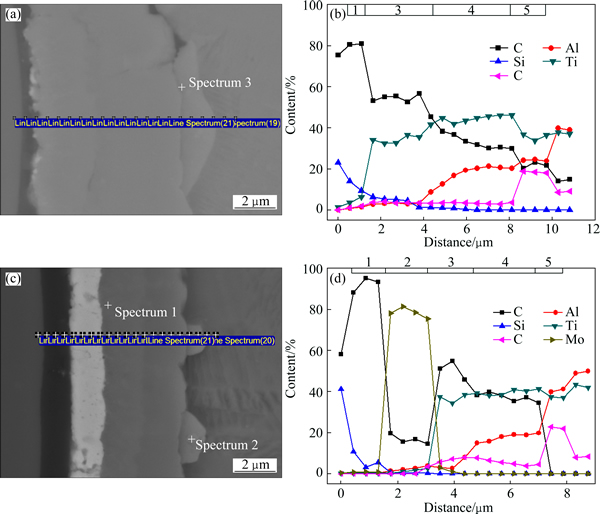
Fig. 7 Interfacial zones of SiCf/C/TiAl (a) and SiCf/C/Mo/TiAl composites (b) after 900 ��C, 200 h thermal exposure and element line analysis results (b, d) corresponding to (a) and (c), respectively
Whether in the SiCf/C/TiAl composite or in the SiCf/C/Mo/TiAl composite, the newly formed layer (hereafter denoted as layer 5) is rich in V. Layer 5, which is circle-shaped in the SiCf/C/TiAl composite, has a V content of about 20%. Similarly, layer 5 with the sawtooth profile in the SiCf/C/Mo/TiAl composite contains approximately 22% V, as listed in Table 2. Besides, Fig. 8 indicates that there exists a concentration gradient of V between the sawtooth-shaped layer 5 and the matrix nearby along the hoop direction. So, one can deduce that the final morphology of layer 5 in SiCf/C/Mo/TiAl composite is also circular after the diffusion of V atoms. In order to verify this presumption, a longer vacuum thermal exposure was carried out.
Table 2 EDS point analysis results of interfacial zone shown in Figs. 7(a) and (c) (mole fraction, %)

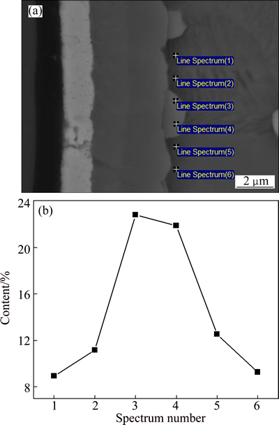
Fig. 8 EDS analysis positions of V-rich layer in composite (a) and corresponding distribution curve of V element (b)
Figure 9 shows the morphology of the SiCf/C/Mo/TiAl composite after 900 ��C, 220 h vacuum thermal exposure. It can be distinctly seen that the layer 5 has became circular by the diffusion of V atoms along the hoop direction. This fact verifies the presumption mentioned above. As shown by spectra 1 and 2 in Table 3, the V content of layer 5 does not decrease obviously accompanying with the growth of layer 5, which infers that the matrix or interfacial layer may provide V element during the growth course. Just like that the interfacial reaction in the SiCf/C/TiAl composite is severer than that in the SiCf/C/Mo/TiAl composite, layer 5 in the SiCf/C/TiAl composite appears earlier and grows bigger (see Fig. 6(c) and Fig. 9) than in the SiCf/C/Mo/TiAl composite. So, the interfacial reaction layer has a greater influence on the formation and growth of layer 5.
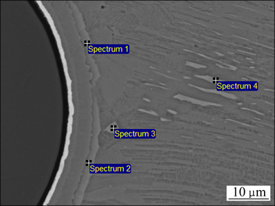
Fig. 9 Interfacial reaction zone of SiCf/C/Mo/TiAl composite after 900 ��C, 220 h thermal exposure
Table 3 EDS point analysis results of positions shown in Fig. 9 (mole fraction, %)
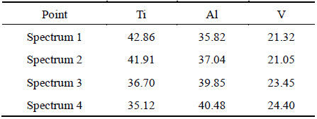
As B2 phase in the matrix is also rich in V, it is necessary to make a componential comparison between layer 5 and B2 phase. As shown in Table 3, the V content of layer 5 approximates to that of B2 phase (Spectra 3 and 4), only the Ti and Al contents having small differences. So, layer 5 should be B2 phase. The formation process of layer 5 should be related to the precipitation of V in (Ti,V)C and (Ti,V)2AlC.
3.3 Interfacial reaction kinetics
As brittle interfacial reaction layer may become potential position for the initiation and growth of cracks which could lower mechanical properties of composites, it is necessary to investigate the growth kinetics of interfacial reaction zone. Figure 10 shows the thicknesses of interfacial reaction layers vs the square roots of vacuum thermal exposure durations under different temperatures. It can be seen that there exists a linear relationship between the two parameters, which suggests that the interfacial reaction is a diffusion- controlled process [27].
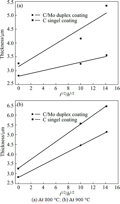
Fig. 10 Interfacial reaction zone thickness as function of square root of time
Therefore, the reaction kinetics can be described by the following equation:
X=kt1/2+b0 (1)
where X is the thickness of the reaction layer, t is duration, k is the reaction rate constant, and b0 is the original thickness of the reaction layer.
The reaction rate constants of SiCf/C/TiAl composite are 0.137 at 800 ��C and 0.227 at 900 ��C, respectively, while those of the SiCf/C/Mo/TiAl composite are 0.0506 at 800 ��C and 0.164 at 900 ��C, respectively. The result shows again that C/Mo duplex coating is more efficient in hindering the interfacial reaction than C single coating.
4 Conclusions
1) The interfacial reaction products of the as-prepared SiCf/C/Mo/TiAl composite are TiC/Ti2AlC from Mo coating side to the matrix, which is the same as that of the as-prepared SiCf/C/TiAl composite. However, the interfacial reaction layer thickness of the former is thinner than that of the latter, which indicates C/Mo duplex coating is more efficient in hindering the interfacial reaction than C single coating.
2) Mo atoms hardly diffuse and dissolve into the g-TiAl matrix, either in the as-prepared or in the thermally-exposed composites. As the bond characteristic of TiAl intermetallics is a mixture of covalent bond and metallic bond, the substitution of Ti atoms with Mo atoms is difficult to occur.
3) Vacuum thermal exposure of the SiCf/C/TiAl and SiCf/C/Mo/TiAl composites shows that C/Mo duplex coating has a better thermal stability at elevated temperatures up to 900 ��C. Meanwhile, with the protection of Mo coating, C coating consumes slower. After the thermal exposure of 900 ��C, 200 h, a V-rich product appears, which might be B2 phase.
References
[1] LIU Yi-wen, HU Rui, ZHANG Tie-bang, KOU Hong-chao, LI Jin-shan. Microstructure evolution and nitrides precipitation in in-situ Ti2AlN/TiAl composites during isothermal aging at 900 ��C [J]. Transactions of Nonferrous Metals Society of China, 2014, 24(5): 1372-1378.
[2] ZHOU Yi, WANG Qing, HAN Xiu-li, SUN Dong-li. Fabrication and properties of continuous unidirectional Mo fiber reinforced TiAl composites by slurry casting and vacuum hot pressing [J]. Compos Sci Technol, 2013, 83: 72-78.
[3] HE Gui-yu, HU Shi-ping, CHU Shuang-jie, ZHANG Tai-xian, CAI Xue-zhang. On development of TiAl intermetallic compound matrix composites with continous Ti-fibers [J]. Journal of Northwestern Polytechnical University, 1995, 13(3): 344-347. (in Chinese)
[4] MACKIN T J, YANG J, WARREN P D. Influence of fiber roughness on the sliding behavior of sapphire fibers in TiAl and glass matrices [J]. J Am Ceram Soc, 1992, 75: 3358-3362.
[5] MILEIKO S T, POVAROVA K B, KORZHOV V P, SEREBRYAKOV A V, KOLCHIN A A, KIIKO V M. High- temperature creep of sapphire-fibre/titanium-aluminide-matrix composites [J]. Scripta Mater, 2001, 44: 2463-2469.
[6] ZHANG Quan-cheng, HE Gui-yu, WU Jian-sheng. Fundamental investigation of TiNb fiber continuously reinforced Ti-48Al-2Cr- 2Nb matrix composites [J]. Materials Science & Technology, 2000, 8(4): 77-79. (in Chinese)
[7] ZHANG W, YANG Y Q, ZHAO G M, HUANG B, FENG Z Q, LUO X, LI M H, LOU J H. Investigation of interfacial reaction in SiC fiber reinforced Ti-43Al-9V composites [J]. Intermetallics, 2013, 33: 54-59.
[8] GOO G K, GRAVES J A, MECARTNEY M L. Interfacial reaction of coated SiC fibers with gamma-TiAl [J]. Scripta Metall, 1992, 26: 1043-1048.
[9] ZHANG W, YANG Y Q, ZHAO G M, FENG Z Q, HUANG B, LUO X, LI M H, CHEN Y X. Interfacial reaction studies of B4C-coated and C-coated SiC fiber reinforced Ti-43Al-9V composites [J]. Intermetallics, 2014, 50: 14-19.
[10] UPADHYAYA D. Development of a superior coating system for continuous silicon carbide fibers for use in titanium based metal matrix composites [D]. Latah: University of Idaho, 1995: 50-178.
[11] WANG Wen-sheng, YAN Yun-qi, LI Zhong-kui. Study on TiAl matrix composites reinforced with fiber [J]. Titanium Industry Progress, 2003, 2: 5-8. (in Chinese)
[12] HUANG Xu, QI Li-chun, LI Zhen-xi. Progress in research of TiAl matrix composites [J]. Rare Metal Mat Eng, 2006, 35(11): 1845-1848. (in Chinese)
[13] ZHOU Yi, SUN Dong-li, WANG Qing, HAN Xiu-li. Effect of fabrication parameters on the microstructure and mechanical properties of unidirectional Mo-fiber reinforced TiAl matrix composites [J]. Mater Sci Eng A, 2013, 575: 21-29.
[14] FU Y C, SHI N L, ZHANG D Z, YANG R. Effects of C coating on the interfacial microstructure and properties of SiC fiber-reinforced Ti matrix composites [J]. Mater Sci Eng A, 2006, 426: 78-282.
[15] LUO Xian, YANG Yan-qing, YU Ying-juan, WANG Xing-rui, HUANG Bin, CHEN Yan. Effect of Mo coating on the interface and mechanical properties of SiC fiber reinforced Ti6Al4V composites [J]. Mater Sci Eng A, 2012, 550: 286-292.
[16] WANG Xing-rui, YANG Yan-qing, LUO Xian, ZHANG Wei, JIN Na, XIAO Zhi-yuan, FENG Guang-hai. Effect of C/Mo duplex coating on the interface and mechanical properties of SiCf/Ti6Al4V composites [J]. Mater Sci Eng A, 2013, 566: 47-53.
[17] ZHU Yan, YANG Yan-qing, SUN Jun. Calculation of activity coefficients for components in ternary Ti alloys and intermetallics as matrix of composites [J]. Transactions of Nonferrous Metals Society of China, 2004, 14(5): 875-879.
[18] QIU Cong-zhang, LIU Yong, HUANG Lan, ZHANG Wei, LIU Bin, LU Bin. Effect of Fe and Mo additions on microstructure and mechanical properties of TiA1 intermetallics [J]. Transactions of Nonferrous Metals Society of China, 2012, 22(3): 521-527.
[19] LA Pei-qing, XUE Qun-ji, LIU Wei-min. Study of wear resistant MoSi2-SiC composites fabricated by self-propagating high temperature synthesis casting [J]. Intermetallics, 2003, 11: 541-550.
[20] ZHANG Wei, YANG Yan-qing, GUO Xiu-qiao, LUO Xian, ZHAO Guang-ming, HUANG Bin. Microstructure of matrix ��-TiAl in SiCf/Ti-43Al-9V composites [J]. Rare Metal Mat Eng, 2013, 42(8): 1726-1729. (in Chinese)
[21] ZHANG Wei. Studies on the microstructure of SiC fiber reinforced TiAl composites [D]. Xi��an: Northwestern Polytechnical University, 2014: 29-31. (in Chinese)
[22] VILLARS P, PRINCE A, OKAMOTO H. Handbook of ternary alloy phase diagrams [M]. Ohio, USA: ASM International, 1995.
[23] QI Z F. Diffusion and phase transformations in solid metals [M]. Beijing: Machine Industry Press, 1998. (in Chinese)
[24] TIAN W H, NEMOTO M. Effect of carbon addition on the microstructures and mechanical properties of ��-TiAl alloys [J]. Intermetallics, 1997, 5: 237-244.
[25] VILLARS P, CALVERT L D. Pearson��s handbook of crystallographic data for intermetallic phases [M]. 2nd ed. Ohio: ASM International, 1991.
[26] ZHOU Yi. Study on preparation, deformation and fracture behavior of Mof/TiAl composites [D]. Harbin: Harbin Institute of Technology, 2013. (in Chinese)
[27] YANG Y Q, DUDEK H J, KUMPFERT J. TEM investigations of the fiber/matrix interface in SCS-6 SiC/Ti-25Al-10Nb-3V-1Mo composites [J]. Composites Part A, 1998, 29: 1235-1241.
C/Mo˫Ϳ��SiC��ά��ǿg-TiAl�����ϲ��ϵ�����֯���������ȶ���
�� �ͣ��� ���������壬��������������� ˧��������
������ҵ��ѧ ���̼��������ص�ʵ���ң����� 710072
ժ Ҫ�����ò�����ά�������Ʊ���C/Mo˫Ϳ��������SiC��ά��ǿ��-TiAl�����ϲ���(SiC/C/Mo/��-TiAl)�����о���������Ч����Ϊ�˶Ա��о�������ͬ�������Ʊ���SiC/C/��-TiAl���ϲ��ϡ������ָ��ϲ�����800 ��C��900 ��C�½����˲�ͬʱ�������ȱ�¶�����������о�������������ȶ��ԡ�����ɨ����������������Ƿ����˸��ϲ��Ͻ��������֯���������������������MoͿ�㣬����SiC/C/Mo/��-TiAl ���ϲ�����SiC/C/��-TiAl���ϲ��ϵĽ��淴Ӧ������һ�£���Ϊ����Ϳ��ͻ���֮���TiC/Ti2AlC�����ǣ���900 ��C���������¶ȣ�C/Mo˫Ϳ���C��Ϳ���ܸ��õ��谭���淴Ӧ�����⣬900 ��C��200 h�ȱ�¶����Ti2AlC�ͻ���֮�䷢����һ���µĽ��淴Ӧ����ò��︻V����B2��Ļ�ѧ�ɷֽӽ���
�ؼ��ʣ�MoͿ�㣻TiAl�Ͻ�SiC��ά���ѻ����ϲ��ϣ����淴Ӧ�����ȶ���
(Edited by Yun-bin HE)
Foundation item: Projects (51201134, 51271147) supported by the National Natural Science Foundation of China; Project (2015JM5181) supported by the Natural Science Foundation of Shaanxi Province, China; Project (115-QP-2014) supported by the Research Fund of the State Key Laboratory of Solidification Processing (NWPU), China; Project (3102014JCQ01023) supported by the Fundamental Research Funds for the Central Universities, China
Corresponding author: Xian LUO; Tel: +86-29-88460536; Fax: +86-29-88460499; E-mail: luoxian@nwpu.edu.cn
DOI: 10.1016/S1003-6326(16)64198-5

