������ĭ�����Ͻṹ��������������
��Դ�ڿ����й���ɫ����ѧ��(Ӣ�İ�)2016���2��
�������ߣ������� ���� ��S ������ �Ż�ΰ ��Դ
����ҳ�룺359 - 368
�ؼ��ʣ����Ͻṹ����������ǿ�ȣ���ĭ�������Σ�������ά
Key words��composite structure; three-point bending strength; aluminum foam sandwich; glass fiber
ժ Ҫ������ĭ�������κ���ά�������Ļ��������һ��������ĭ�����Ͻṹ�����ָ��Ͻṹ���ڽ���������ĭ��о��֮������һ�㲣����ά�����ý�ճ���������������-������ά-��ĭ��-������ά-������塱��˳��ճ��������ʵ������ʾ�������Ͻṹ�������ĭ�������ε��ۺ�����������ߡ��õ���������ĭ�����Ͻṹ������ǿ�����ʱ�������Ʊ�������Ӧѡ������֬�����Ϳ�϶�ʵ���ĭ��������������Ϊ1.5 mm��������ά�����������ǿ�ȵ�Ӱ���С�������������Ͻṹ������ճ����µ���ҪʧЧģʽ��
Abstract: A new composite structure based on aluminum foam sandwich and fiber metal laminate was proposed. A layer of glass fiber was provided at the interface between the metal panel and the aluminum foam core in this composite structure, using adhesive technology to bond the materials together by organic glue in the sequence of metal panel, glass fiber, aluminum foam core, glass fiber and metal panel. The experimental results show that the new composite structure has an improved comprehensive performance compared with the traditional aluminum foam sandwiches. The optimized parameters for the fabrication of the new aluminum foam composite structure with best bending strength were obtained. The epoxy resin and low porosity aluminum foams are preferred, the thickness of aluminum sheets should be at least 1.5 mm, and the type of glass fiber has little effect on the bending strength. The main failure modes of the new composite structures with two types of glues were discussed.
Trans. Nonferrous Met. Soc. China 26(2016) 359-368
Ning-zhen WANG1, Xiang CHEN1,2, Ao LI3, Yan-xiang LI1,2, Hua-wei ZHANG1,2, Yuan LIU1,2
1. School of Materials Science and Engineering, Tsinghua University, Beijing 100084, China;
2. Key Laboratory for Advanced Materials Processing Technology, Ministry of Education, Tsinghua University, Beijing 100084, China;
3. Department of Mechanical Engineering, Tsinghua University, Beijing 100084, China
Received 30 January 2015; accepted 15 September 2015
Abstract: A new composite structure based on aluminum foam sandwich and fiber metal laminate was proposed. A layer of glass fiber was provided at the interface between the metal panel and the aluminum foam core in this composite structure, using adhesive technology to bond the materials together by organic glue in the sequence of metal panel, glass fiber, aluminum foam core, glass fiber and metal panel. The experimental results show that the new composite structure has an improved comprehensive performance compared with the traditional aluminum foam sandwiches. The optimized parameters for the fabrication of the new aluminum foam composite structure with best bending strength were obtained. The epoxy resin and low porosity aluminum foams are preferred, the thickness of aluminum sheets should be at least 1.5 mm, and the type of glass fiber has little effect on the bending strength. The main failure modes of the new composite structures with two types of glues were discussed.
Key words: composite structure; three-point bending strength; aluminum foam sandwich; glass fiber
1 Introduction
The properties of aluminum foam are superior to traditional aluminum because of its porous structure. As a functional material, open-cell aluminum foam has excellent electromagnetic shielding capacities, good noise reduction and closed-cell aluminum foam possesses high shock absorption capacity. As a structural material, aluminum foam has low density and high specific strength. Because of the existence of the internal trapped gas, the closed-cell aluminum foam has better mechanical properties with respect to open-cell aluminum foam. Many researches have been carried out on closed-cell aluminum foam as a structural material [1-5], and most studies on the mechanical properties of pure aluminum foams were focused on energy absorption performance in quasi-static compression or dynamic compression tests. One problem is that comprehensive mechanical properties of closed-cell aluminum foam are not good enough to meet the requirements of industrial applications. Therefore, the aluminum foam sandwich (AFS) has been developed for its improved strength while retaining the excellent properties of aluminum foam.
Metal panels and aluminum foam core constitute the aluminum foam sandwich. The main ways to manufacture AFS are by powder metallurgy route and adhesive route. KITAZONO et al [6] reported that the adhesive prevents local buckling of the cell walls by infilling the open cell surface, so the adhesive coating can increase the mechanical properties of aluminum foam. Although some researches [7,8] showed that the metallurgical bonding interface is stronger than that of adhesive bonding, the lower cost and the simpler process have given adhesive technology a better application prospect.
Fiber metal laminates (FML), made by aluminum plates and fiber-reinforced resin layers laminated alternately, were developed by Delft University in the Netherlands and the Fokker Aircraft Company in the 1970s. There are two types of fiber metal laminates, named Arall (Aramid Reinforced Aluminum Laminate) and Glare (Fiberglass Reinforced Aluminum Laminate), the fibers in which are aramid fiber and glass fiber, respectively. Glare overcomes the shortcomings of sensitivity to gap and impact in Arall and improves the biaxial stress fatigue properties, so it gets a better application prospect [9]. The base materials in Glare are aluminum alloy sheet, glass fiber and epoxy resin. Glare combines the advantages of both metal and composite materials, especially for low density, high strength, high fatigue resistance, high impact resistance, excellent corrosion resistance, flame retardance and relatively low cost. This gives it a broad application and great potential in the aviation industry. The first successful application of Glare was in the skin structure and leading edge of the wing and empennage in the Airbus A380 aircraft. The application area reached 380 m2 and achieved a mass reduction of 794 kg [10].
Based on the AFS with adhesive bonding and Glare plate, a new aluminum foam composite structure which is named as glass fiber reinforced aluminum foam laminate (GRAFL) was proposed, which was fabricated by adding a layer of glass fiber to the interface between the metal panel and the aluminum foam core of AFS. Adhesive technology was used to bond the materials together in the sequence of metal panel, glass fiber, aluminum foam core, glass fiber and metal panel, as shown in Fig. 1. The new composite structure is a material with the integration of structure and function, and it has very wide application prospects in the fields of ship manufacturing, aerospace, automobile manufacturing and transportation. The anti-bending performance is an important property index of the composite sheets, and the response to three-point bending of AFS with adhesive bonding was investigated in many studies [11-15] through experimental and theoretical analysis, which discussed various failure modes related to the geometric and material factors. The main failure modes of AFS are face yield, indentation and core shear in the literature previously mentioned. In this work, the influence of the thickness of panels, the glass fiber, the porosity of aluminum foam, and the type and amount of glues on the three-point bending performance of the new composite structure were studied. The parameters of materials which gave the best mechanical properties were obtained, and the performance of the new aluminum foam composite structure was compared with that of AFS. Moreover, the main deformation and failure modes of the new composite structure were discussed.
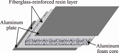
Fig. 1 Schematic diagram of new aluminum foam composite structure
2 Experimental
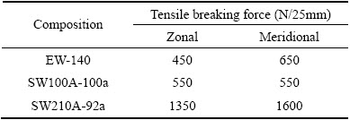
The aluminum foam core, two metal panels and glass fiber sheets were all in the size of 200 mm �� 50 mm. The aluminum foams with a thickness of 10 mm were prepared by melt foaming process. The aluminum foam sheets used in the experiments were carefully selected, the pores of which were relatively uniform. So, the differences between the aluminum foams were not considered except for porosity. Commercial aluminum panels were used as metal panels because of their light weight. Three aluminum panel thicknesses were adopted, namely 0.5, 1 and 1.5 mm. Three glass fibers were used for comparative analysis. Their grades and tensile breaking strength are shown in Table 1. The thicknesses of fibers 1, 2 and 3 are 0.2, 0.1 and 0.21 mm, respectively. Fibers 2 and 3 are high-strength glass fibers, so the monofilaments of fibers 2 and 3 have superior mechanical properties compared with fiber 1. Two kinds of commercial adhesive were used in the experiments, namely Kafuter K-801 AB glue and Kafuter epoxy glue with epoxy curing agent. Kafuter K-801 AB glue, which is a kind of modified acrylate adhesive, is also called green-red glue. Kafuter epoxy glue mixing with epoxy curing agent is called epoxy resin in this work. The epoxy resin is used as binder in the Glare plate, but it needs 3 to 5 h to reach initial curing, the aluminum foam and panels are easy to dislocate with each other in the curing process. The green-red glue can reach initial curing in 3 to 5 min, therefore, green-red glue was chosen as a comparison for its easy use.
Table 1 Grades and strength of glass fibers used in experiments
The aluminum foams and aluminum panels were firstly sanded with sandpaper, to remove the oxide film on the surface. Moreover, the surface became rough after sanding which was conducive to the good adhesion of glue. Then, the sanded panels were washed using ethanol to further remove impurities. Equation (1) was used to calculate the porosity of aluminum foams, and the specific porosities of aluminum foams were selected for the experiments. The mass of adhesive was obtained by subtracting the mass of other materials from the total mass after bonding and drying.
 (1)
(1)
where p, m, and V are the porosity, density, mass and volume of the aluminum foam, respectively and �� is the density of pure aluminum.
The specimens were bonded with the order of aluminum panel-glass fiber-aluminum foam core-glass fiber-aluminum panel.
Two different coating conditions were used. The first route, which is named coating condition 1, was a coating with green-red glue: the glue was coated on the adhesive surfaces with green glue on one side and red glue on the other side. The sample should be pressed for more than 30 min with a certain press force after bonding. The second route, which is named coating condition 2, was a coating with epoxy resin: the epoxy resin was uniformly brushed on the adhesive surfaces after the epoxy glue and curing agent were evenly mixed, then the sample was fixed to solidify for more than 24 h.
The three-point bending tests were conducted on a WDW-100E electronic universal testing machine at the loading rate of 5 mm/min. The size of the samples was 200 mm in length and 50 mm in width; and the span during the tests was 180 mm. The load-displacement curves were obtained from the experiments, the samples were considered to have failed when the curves were in steady decline section. Figure 2 shows the schematic diagram for the three-point bending tests. The peak load F could be obtained from the three-point bending tests, and the bending strength R was calculated using Eq. (2). The three-point bending strength values in each condition reported in this work were the averages of three tests.
 (2)
(2)
where l is the size of the span, b and h are the width and thickness of the specimen, respectively, and F is the peak load during the test.
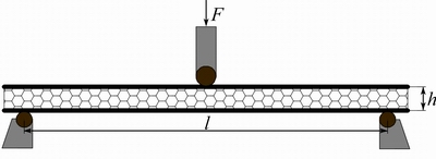
Fig. 2 Schematic diagram of three-point bending test
3 Results and discussion
3.1 Influence of aluminum panel thickness on three- point bending strength
The specimens with aluminum panel thicknesses of 0.5, 1 and 1.5 mm and two coating conditions were tested, and the three-point bending strengths with different thicknesses of aluminum panels and coating conditions are shown in Fig. 3, where the mass of glue was controlled approximately the same in each coating condition. The porosity of the aluminum foams was about 90 %, and fiber 3 was used.
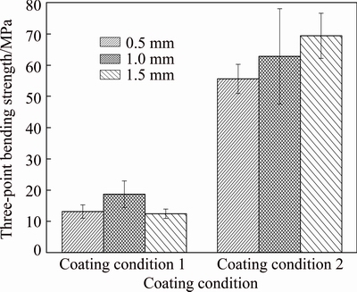
Fig. 3 Influence of aluminum panel thickness on three-point bending strength
It can be seen from Fig. 3 that the bending strength of the composite structure under coating condition 2 (epoxy resin coating) was significantly higher than that of the composite structure under coating condition 1 (green-red glue coating). The thickness of aluminum panel is positively correlated with its strength, but the rule does not apply for the new composite structure. There was a best fit between the strength of aluminum panel and adhesive during deformation. The toughness of green-red glue is better than that of epoxy resin and its strength is lower [16], so it could be deformed together with the thinner panel and less prone to generate the internal stress. Therefore, the specimen with the sheet thickness of 1 mm had the highest bending strength in coating condition 1. After consolidation, the strength of epoxy resin was high enough to coordinately deform with the 1.5 mm panel, so the highest bending strength appeared in the specimen with 1.5 mm panel in coating condition 2.
Figure 4 shows the failure specimens with different thicknesses of panels in two coating conditions. As shown in Fig. 4, the strength of 1.5 mm aluminum panels was too high for the sample in coating condition 1, so uncoordinated deformation between aluminum panels and the other parts promoted the crack extension of aluminum foam, which was under high tension and shear stress (Fig. 4(a)). But the 0.5 mm panel was too flexible for epoxy resin in coating condition 2, and poor fit between the strength of aluminum panel and the other parts caused the buckling of aluminum sheet (Fig. 4(b)).
3.2 Influence of glass fiber on three-point bending strength
Specimens with fiber 1, fiber 2, fiber 3 and no fiber (AFS) in the two coating conditions were tested. The three-point bending strengths with different fibers and coating conditions are shown in Fig. 5. The thicknesses of aluminum sheets were all about 1 mm and the mass of glue was controlled approximately the same in each coating condition. The porosity of aluminum foams was about 90 % in both coating conditions.
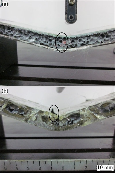
Fig. 4 Failure specimen with 1.5 mm thick panel in coating condition 1 (a) and failure specimen with 0.5 mm thick panel in coating condition 2 (b)
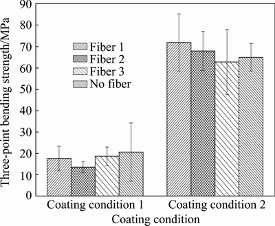
Fig. 5 Influence of glass fiber on three-point bending strength
It can be seen from Fig. 5 that in coating conditions 1 and 2, the bending strengths of AFS specimens were not low, and even higher than some new composite structure specimens, but their overall performance was not good. Figure 6 shows the load-displacement curves for the new composite structure and AFS. As shown in Fig. 6, although the peak load of AFS was higher, a low extended plateau region appeared after the high peak load, which resulted in a poor energy absorption property during compression process. Figure 7 shows the comparison of the failure specimens between the new composite structure and AFS in coating condition 2. The bonding interface did not fail due to the high bond strength, and a core transverse shear failure appeared instead in the new composite structure (Fig. 7(a)). Because the stress was too high for AFS to withstand, the fracture occurred and the crack extended from the lower plate of AFS to the interior of the aluminum foam (Fig. 7(b)). The AFS samples in other groups of coating condition 2 also showed cracks in lower plate, while the new composite structure samples mainly failed in aluminum foams. Therefore, it was not easy to produce cracks in the lower plate of the new composite structure due to the high strength of glass fiber filament. Moreover, most samples maintained integrity even after failure, which gave an extra kind of security. The core shear failure of the new composite structure can be avoided by the glue coating on the sidewall of aluminum foam. The glue on the sidewall could prevent the local yielding and fracture in the edge, thus avoiding the extension of the crack from the edge.
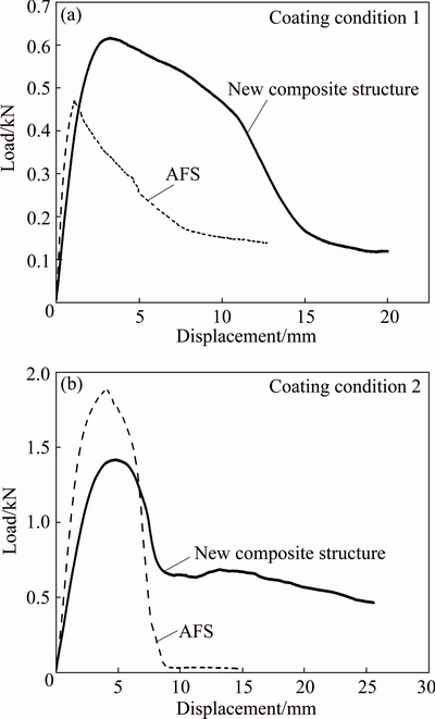
Fig. 6 Comparison of load-displacement curves for new composite structure (fiber 3 was used) and AFS coated with green-red glue (a) and epoxy resin (b)
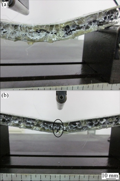
Fig. 7 Failure specimen of new composite structure (fiber 3 was used) (a) and failure specimen of AFS in coating condition 2 (b)
Fiber 1 is an E-glass fiber, the monofilament strength of which is lower than those of fibers 2 and 3. But in coating condition 1, the three-point bending strengths of the specimens with fiber 1 were all relatively high. That was because the larger pores between the filaments were conducive to the penetration of the glue in fiber 1, which was equivalent to an increase of the thickness of the adhesive layer. For the short curing time of green-red glue, the penetration of glue made the bending strength of the sample with fiber 1 higher. Fibers 2 and 3 are both high-strength fibers, but the strength of fiber 3 is higher due to the greater thickness, so the three-point bending strength of the sample with fiber 3 was the highest in coating condition 1. Therefore, the reinforcing effect of glass fiber for the new composite structure is not only related to the monofilament strength, but also related to the size of pores between filaments, namely the filament density. An anomalous phenomenon was that the bending strength of the specimens with fiber 3 was the lowest in coating condition 2. As shown in Fig. 8, the specimens with fibers 1, 2 and 3 all failed in the core transverse shear mode. The longer curing time of epoxy resin made it permeate sufficiently in fibers 1, 2 and 3, so the strength of the resin fiber layer was high enough during deformation. Also, because of the high strength of epoxy resin, the stress on the specimens in coating condition 2 was higher than that in coating condition 1, as shown in Figs. 5 and 6. The stress was too large for the aluminum foam to withstand, so the failure was mainly related to defects in the aluminum foam itself. And the difference of fibers had little effect on the bending strength of the new composite structure. However, the presence of the glass fiber made the lower plate of the composite structure not easy to have cracks and increased the height of the platform in load-displacement curve.
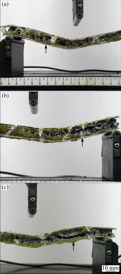
Fig. 8 Failure specimens of new composite structure with fiber 1 (a), fiber 2 (b) and fiber 3 (c) in coating condition 2
In Fig. 3 and Fig. 5, it is remarkable that the strengths of the new composite structures with epoxy resin are higher than that with green-red glue. The strength of epoxy resin is higher than that of green-red glue after consolidation [16] and it could permeate sufficiently into the glass fibers, which are both conducive to enhancing the strength of the composite structure. Therefore, epoxy resin is the preferred adhesive.
3.3 Influence of aluminum foam porosity on three- point bending strength
The specimens with different porosities in two coating conditions were tested, and the three-point bending strengths with different aluminum foam porosities and coating conditions are shown in Fig. 9. The thicknesses of aluminum sheets were all about 1 mm, fiber 3 was used in all samples and the mass of glue was controlled approximately the same in each coating condition.
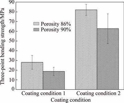
Fig. 9 Influence of aluminum foam porosity on three-point bending strength
It can be seen from Fig. 9 that the three-point bending strength increased with a decrease in the porosity of aluminum foam. It was firstly due to the strength of aluminum foam itself increasing with the decrease of porosity. The second reason was that the contact area between aluminum foam and adhesive increased with the decrease of porosity, which resulted in the enhancement of bonding effect, and then the three-point bending strength increased. Therefore, in order to improve the bending strength of the new composite structure, the aluminum foams with lower porosity are preferred on the lightweight premise.
3.4 Influence of amount of glue on three-point bending strength
The specimens with different amounts of glue in two coating conditions were tested, and the three-point bending strength with different amounts of glue and in different coating conditions are shown in Fig. 10. The thicknesses of aluminum sheets were all about 1 mm. In coating conditions 1 and 2, the porosity of aluminum foams was about 90 % and fiber 3 was used. Figure 11 shows the failure specimens with different amounts of glue in coating condition 1.
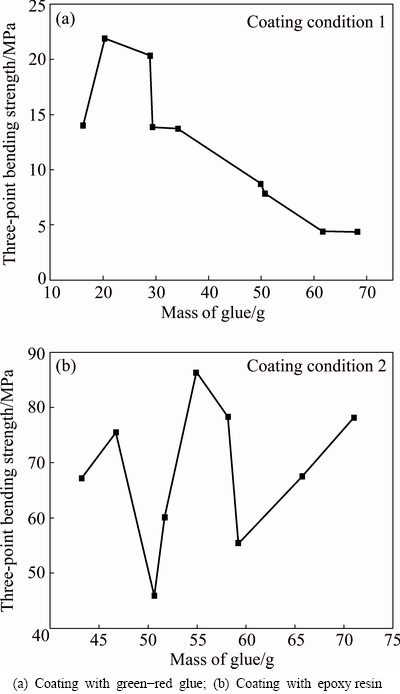
Fig. 10 Influence of amount of glue on three-point bending strength
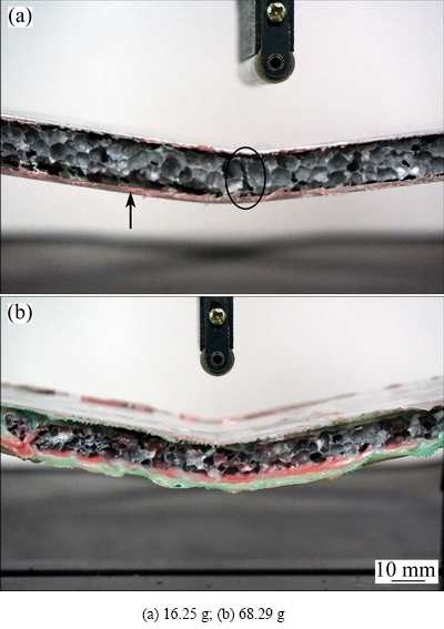
Fig. 11 Failure specimens with different amounts of green-red glue in coating condition 1
Everyone can get a conclusion from Fig. 10(a) that the three-point bending strength increased firstly and then decreased with an increase in the amount of glue in coating condition 1. The increase of the three-point bending strength was due to the enhancement of the bonding effect of the green-red glue. Because the curing time of the green-red glue was too short, the glue cannot fully penetrate to the cells of aluminum foam. Then, the bonding effect would not be satisfactory when the amount of glue was not enough. Moreover, the specimen was not prone to brittle failure because of the improvement in toughness when the amount of glue increased. As shown in Fig. 11(a), the weak bonding effect made the aluminum foam partly disengaged from the lower plate with fiber, and the glue adhered on the surface of aluminum foam was too small to avoid the formation of brittle cracks. Figure 10(a) also shows that the bending strength decreased with an increase in amount when the amount of green-red glue was too large. It is because the green-red glue has low intensity, good toughness and is easy to bend. When the amount of glue was large enough, the performance of the specimen was greatly influenced by green red glue and the bending strength was low. As shown in Fig. 11(b), the sample did not show any bending crack due to the existence of large amount of green red glue. For the sample size in this work, the three-point bending strength of the new composite structure decreased with an increase in the amount when the mass of green-red glue was greater than 25 g. Moreover, it is not easy to meet the requirement of light weight when the amount of glue is too large. So, the adhesive should be in a suitable amount during bonding, especially for green-red glue.
Figure 10(b) shows that there was no obvious regularity between the three-point bending strength and mass of epoxy resin. In coating condition 2, more pores of aluminum foam were filled by epoxy resin due to the long time of consolidation compared with coating condition 1. Moreover, the interface between glue and aluminum foam was strong because of the high strength of epoxy resin, so the aluminum foam was hard to disengage from the glass fiber. Because of the long curing time and high strength of epoxy resin, the amount of resin had little influence on the bending strength as long as the resin was not particularly lacking, but it could affect the failure modes. The sample failed in the defects of aluminum foam, and the core transverse shear appeared because the aluminum foam strength was not sufficient, as shown in Fig. 12(a). Figure 12(b) shows that when the amount of resin was large enough, the specimen showed buckling failure on the upper plate. Even if the local micro cracks had formed, the cracks were difficult to propagate because of the good adhesion of the epoxy resin. The epoxy resin buffered the stress and absorbed the compression energy through recessing and buckling of the upper plate in the region around loading roller. As shown in Fig. 4(b) and Fig. 12(b), either too thin of aluminum sheet or too large amount of resin was easy to cause wrinkles on the upper plate in coating condition 2.
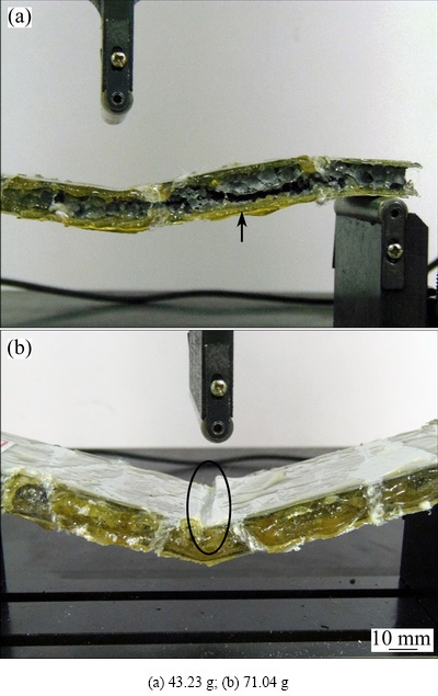
Fig. 12 Failure specimens with different amounts of epoxy resin in coating condition 2
3.5 Failure modes of new composite structure
The failure modes were different in different coating conditions. When coating with green-red glue, the majority of the specimens failed in both the core cracks and delamination between the aluminum foam core and lower plate as shown in Figs. 13(a) and (b). This kind of failure was caused by core yield. As shown in Fig. 14, there are two types of core yield modes [11,17,18], mode A and mode B. In mode A, the plastic hinges were at around the loading points, and the specimen which failed in this mode was shown in Fig. 13(a). The lower part of the core was under tensile stress and shear stress due to the presence of plastic hinges in the bending process, so the lower part of the aluminum foam cracked and the cracks extended gradually, then the tilted aluminum foam eventually led to the delamination between the core and lower plate. Glass fiber was generally bonded together with the lower plate when delamination occurred, because of the larger contact area between glass fiber and the lower plate. In mode B, the plastic hinges were located at the loading points and supporting points, the specimen failed in this mode was shown in Fig. 13(b). The core cracks and delamination occurred at the boundary in these specimens, which was due to the existence of the plastic hinges in supporting positions [19], as shown in Fig. 14(b). Some specimens exhibited no obvious failure as shown in Fig. 13(c), and this was because the good plasticity of green-red glue made them have a large deformation before failure. There was also a sample with wrinkle in the upper plate due to debonding between the green-red glue and aluminum foam, as shown in Fig. 13(d), and it was attributed to the causal factors during bonding.
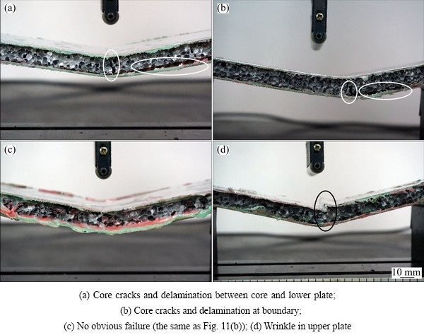
Fig. 13 Failure modes of specimens coating with green-red glue
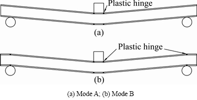
Fig. 14 Schematics of core yield
When coating with epoxy resin, the majority of the specimens were failed in the core transverse shear failure as shown in Fig. 15(a). The core shear failure occurred when the interfacial strength was higher than the core shear strength, thus the high strength resin fiber layer led to the transverse shear failure in the aluminum foam itself. In our experiments, all the AFS specimens when coating with epoxy resin failed in the cracks on the lower plate and core. In addition to the AFS, Fig. 15(b) shows that some new composite structures also failed in this way just not as serious as in AFS. The brittle fractures were caused by the brittleness of the epoxy resin. According to experimental statistics in this work, when the mass of epoxy resin was greater than 58 g for the sample size, buckling failure occurred on the upper plate of the specimens as shown in Fig. 15(c). Besides, a sample with 0.5 mm thick panel also failed in the same way. The occurrence of buckling failure was because that the strength of resin fiber layer was higher than that of face sheets, then the epoxy resin buffered the stress and absorbed the compression energy through recessing and buckling of the upper plate in the region around the loading roller. Figure 15(d) shows that a delamination occurred between skin and core with fiber, it may be that the roughnesses of the panels were not enough after sanding, and then further the bonding effect was not satisfactory.
In summary, there were three main failure modes when coated with green red glue, 1) core cracks and delamination between the core and lower plate; 2) no obvious failure; 3) wrinkle in the upper plate. The failures were due to the weak bonding between the core and green-red glue, the good plasticity and short curing time of green-red glue. Similarity, three main failure molds were observed in the specimens coated with epoxy resin: 1) core transverse shear, 2) cracks on the lower plate and core, and 3) buckling failure on the upper plate. The failures were due to the high strength of resin fiber layer, the brittleness and long curing time of epoxy resin. So, the type of adhesive is the main influencing factor for the failure modes of the new composite structure. The thickness of panel, the presence of glass fiber and the mass of adhesive also have some effects on the failure modes.
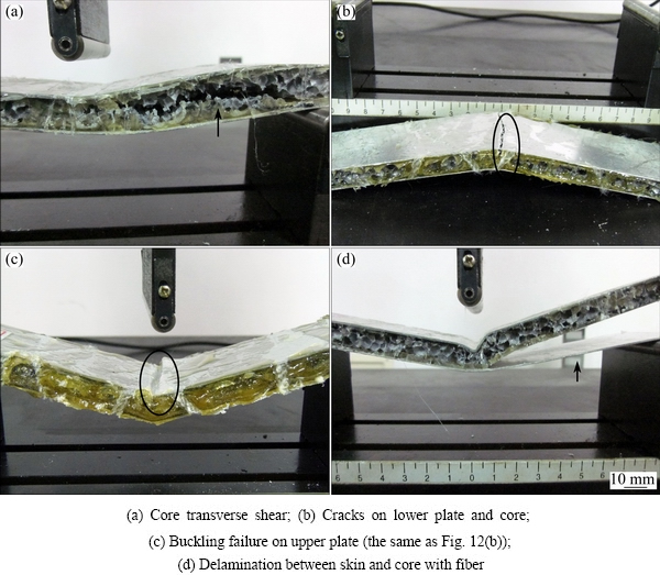
Fig. 15 Failure modes of specimens coating with epoxy resin
4 Conclusions
1) Because of the low platform height in load- displacement curve, the energy absorption capacity of traditional AFS is lower compared with that of the new aluminum foam composite structure. Moreover, the lower plate of the new composite structure is not likely to show cracks due to the high strength of the glass fiber filament, but the lower plates of the AFS specimens are more likely to fracture. The new aluminum foam composite structure could maintain integrity even after failure, which helps to avoid possible dangerous situations in practical applications. So, the new structure has an improved comprehensive performance compared with traditional AFS.
2) The three-point bending strength tests showed that the strength of the specimens with epoxy resin was higher than that with green-red glue. Therefore, in order to obtain the highest bending strength in the sample size of this work, epoxy resin is preferred. The optimized parameters of materials which give the best bending strength are as follows: the thickness of aluminum sheet should be at least 1.5 mm; the type of glass fiber and the amount of epoxy resin have little effect on the bending strength because the strength of resin fiber layer is high enough for the composite structure (the amount of epoxy resin should not be too much for the weight reduction of sample); the aluminum foam with low porosity is preferred.
3) To reduce the curing time, the green-red glue should be chosen. The highest three-point bending strength could be reached by the aluminum sheets with a thickness of 1 mm, the glass fiber with big pores between filaments and high monofilament strength, the aluminum foam with low porosity and the around of 25 g glue mass for the samples.
4) The main influencing factors for the failure modes of the new composite structure are the strength and curing time of the adhesive. The thickness of panel, the presence of glass fiber and the mass of adhesive also have some effects on the failure modes.
References
[1] ANDREWS E, SANDERS W, GIBSON L J. Compressive and tensile behavior of aluminum foams [J]. Materials Science and Engineering A, 1999, 270(2): 113-124.
[2] MU Yong-liang, YAO Guang-chun, LIANG Li-si, LUO Hong-jie, ZU Guo-yin. Deformation mechanisms of closed-cell aluminum foam in compression [J]. Scripta Materialia, 2010, 63(6): 629-632.
[3] EDWIN R R, PARAMESWARAN V, DANIEL B S S. Comparison of quasi-static and dynamic compression behavior of closed-cell aluminum foam [J]. Materials Science and Engineering A, 2009, 526(1-2): 11-15.
[4] YUAN Jian-yu, LI Yan-xiang. Effects of cell wall property on compressive performance of aluminum foams [J]. Transactions of Nonferrous Metals Society of China, 2015, 25(5): 1619-1625.
[5] HEYDARI ASTARAIE A, SHAHVERDI H R, ELAHI S H. Compressive behavior of Zn-22Al closed-cell foams under uniaxial quasi-static loading [J]. Transactions of Nonferrous Metals Society of China, 2015, 25(1): 162-169.
[6] KITAZONO K, TAKEDA T, SUZUKI R. Control of mechanical properties of closed-cell aluminum foams by epoxy resin coating [C]//Proceedings of the 7th International Conference on Porous Metals and Metallic Foams. Seoul, Korea: GS Intervision, 2011: 283-288.
[7] ZU Guo-yin, SONG Bin-na, ZHONG Zhao-yang, LI Xiao-bing, MU Yong-liang, YAO Guang-chun. Static three-point bending behavior of aluminum foam sandwich [J]. Journal of Alloys and Compounds, 2012, 540: 275-278.
[8] CRUPI V, MONTANINI R. Aluminium foam sandwiches collapse modes under static and dynamic three-point bending [J]. International Journal of Impact Engineering, 2007, 34(3): 509-521.
[9] WANG Shi-ming, WU Zhong-qing, ZHANG Zhen-jun, GUAN Tian-ru, CHEN Zhao-feng. Research of glare laminates performance comprehensive evaluation applied to large aircraft [J]. Materials Review, 2010, 24(9): 88-95.
[10] WU G C, YANG J M. The mechanical behavior of GLARE laminates for aircraft structures [J]. JOM, 2005, 57(1): 72-79.
[11] MCCORMACK T M, MILLER R, KESLER O, GIBSON L J. Failure of sandwich beams with metallic foam cores [J]. International Journal of Solids and Structures, 2001, 38(28): 4901-4920.
[12] KABIR K R, VODENITCHAROVA T, HOFFMAN M. Structural response of aluminum foam hybrid sandwich panels under three-point bending loading [J]. International Journal of Modern Physics B, 2009, 23(6-7): 1733-1738.
[13] ZU Guo-yin, LU Ri-huan, Li Xiao-bing, ZHONG Zhao-yang, MA Xing-jiang, HAN Ming-bo, YAO Guang-chun. Three-point bending behavior of aluminum foam sandwich with steel panel [J]. Transactions of Nonferrous Metals Society of China, 2013, 23(9): 2491-2495.
[14] KABIR K, VODENITCHAROVA T, HOFFMAN M. Response of aluminium foam-cored sandwich panels to bending load [J]. Composites Part B: Engineering, 2014, 64: 24-32.
[15] LI Zhi-bin, ZHENG Zhi-jun, YU Ji-lin, QIAN Chun-qiang, LU Fang-yun. Deformation and failure mechanisms of sandwich beams under three-point bending at elevated temperatures [J]. Composite Structures, 2014, 111: 285-290.
[16] CAO Duan-qing. The modification of epoxy resin by acrylic acid [D]. Nanchang: Nanchang Hangkong University, 2008. (in Chinese)
[17] CHEN C, HARTE A M, FLECK N A. The plastic collapse of sandwich beams with a metallic foam core [J]. International Journal of Mechanical Sciences, 2001, 43(6): 1483-1506.
[18] ZHU Xiao-lei, AI Shi-gang, LU Xiao-feng, CHENG Ke, LING Xiang, ZHU Ling-xue, LIU Bin. Collapse models of aluminum foam sandwiches under static three-point bending based on 3D geometrical reconstruction [J]. Computational Materials Science, 2014, 85: 38-45.
[19] JING Lin, WANG Zhi-hua, NING Jian-guo, ZHAO Long-mao. The dynamic response of sandwich beams with open-cell metal foam cores [J]. Composites Part B: Engineering, 2011, 42(1): 1-10.
������1���� ��1,2���� �S3��������1,2���Ż�ΰ1,2���� Դ1,2
1. �廪��ѧ ����ѧԺ������ 100084��
2. �廪��ѧ �Ƚ���������������ص�ʵ���ң����� 100084��
3. �廪��ѧ ��е����ϵ������ 100084
ժ Ҫ������ĭ�������κ���ά�������Ļ��������һ��������ĭ�����Ͻṹ�����ָ��Ͻṹ���ڽ���������ĭ��о��֮������һ�㲣����ά�����ý�ճ���������������-������ά-��ĭ��-������ά-������塱��˳��ճ��������ʵ������ʾ�������Ͻṹ�������ĭ�������ε��ۺ�����������ߡ��õ���������ĭ�����Ͻṹ������ǿ�����ʱ�������Ʊ�������Ӧѡ������֬�����Ϳ�϶�ʵ���ĭ��������������Ϊ1.5 mm��������ά�����������ǿ�ȵ�Ӱ���С�������������Ͻṹ������ճ����µ���ҪʧЧģʽ��
�ؼ��ʣ����Ͻṹ����������ǿ�ȣ���ĭ�������Σ�������ά
(Edited by Yun-bin HE)
Foundation item: Project (SS2015AA031101) supported by the National High-tech R&D Program of China
Corresponding author: Xiang CHEN; Tel: +86-10-62789328; E-mail: xchen@tsinghua.edu.cn
DOI: 10.1016/S1003-6326(16)64088-8

