
Growth and corrosion resistance of molybdate modified zinc phosphate conversion coatings on hot-dip galvanized steel
LIN Bi-lan(林碧兰), LU Jin-tang(卢锦堂), KONG Gang(孔 纲), LIU Jun(刘 军)
School of Materials Science and Engineering, South China University of Technology, Guangzhou 510640, China
Received 17 October 2006; accepted 21 May 2007
Abstract: The modified zinc phosphate conversion coatings(ZPC) were formed on hot-dip galvanized(HDG) steel when 1.0 g/L sodium molybdate were added in a traditional zinc phosphate solution. The growth performance and corrosion resistance of the modified ZPC were investigated by SEM, open circuit potential(OCP), mass gain, potentiodynamic polarization and electrochemical impedance spectroscopy(EIS) measurements and compared with those of the traditional ZPC. The results show that if sodium molybdate is added in a traditional zinc phosphate solution, the nucleation of zinc phosphate crystals is increased obviously; zinc phosphate crystals are changed from bulky acicular to fine flake and a more compact ZPC is obtained. Moreover, the mass gain and coverage of the modified ZPC are also boosted. The corrosion resistance of ZPC is increased with an increase in coverage, and thus the corrosion protection ability of the modified ZPC for HDG steel is more outstanding than that of the traditional ZPC.
Key words: zinc phosphate conversion coatings; molybdate; growth performance; corrosion resistance
1 Introduction
Phosphating is one of the most important chemical conversion processes for the purposes of corrosion protection and primer for painting. ZPC with lightmass are commonly used as the painting primer. Generally, the corrosion resistance of phosphate coatings is correlated with their coverage intimately, which in turn is decided by the structure and size of phosphate crystals. Recently, literatures concerned improving the corrosion resistance of phosphate coatings by varying the pretreatment methods before phosphating and the process technologies for phosphating were frequently reported [1-5]. The direct objects of those measures were to change the structure of phosphate crystals, decline the grain size and enhance the coverage of phosphate coatings[6-8].
Molybdate is an environmentally acceptable and effective corrosion inhibitor for zinc, galvanized steel and other metals[9-10]. Molybdate conversion coatings on HDG steel were also documented[11-12]. Recently, work about molybdate added in a zinc phosphate solution to improve the corrosion resistance or to accelerate the phosphating process for steel and magnet was also reported[13-14]. But research about molybdate modified ZPC on HDG steel has not been reported yet. Furthermore, the details of the relation between the growth performance and the corrosion resistance of molybdate modified ZPC were not well understood. The present study aims to address these points by examining with SEM and electrochemical techniques.
2 Experimental
Cold rolled steel sheets Q235 of 50 mm×40 mm×2 mm were degreased, pickled, fluxed in a mixed solution with 30 g/L NH4Cl and 20 g/L ZnCl2 at 60 ℃, dried and dipped in a zinc bath at 450 ℃ for 1 min, and then withdrawn slowly and quenched in water immediately. The thickness of the HDG layer measured by magnetic thickness gauge was about 50 μm.
Two category samples for comparison were HDG samples phosphated in a modified zinc phosphate solution containing sodium molybdate (denoted as “MP”) and in a traditional zinc phosphate solution without sodium molybdate additives (denoted as “TP”), respectively.
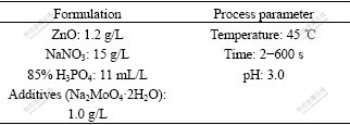
The formulations and process parameters for the modified zinc phosphate solution are listed in Table 1,and those for the traditional one are the same merely without sodium molybdate additives. The solutions were prepared from reagent grade chemicals and de-ionized water.
Table 1 Formulations and process parameters for modified zinc phosphate solution
The electrochemical measurements were carried out using a potentiostat/galvanostat response analyzer of electrochemical workstation (Model: CHI 604B). A saturated calomel electrode(SCE) was used as a reference electrode. The OCP measurements during phosphating were performed in the prepared phosphating solution fixed at 45 ℃.
To measure the corrosion resistance of ZPC, the potentiodynamic polarization and EIS measurements were performed with a conventional three-electrode cell in a non-deaerated 5% NaCl at room temperature. A platinum electrode of 10 cm2 was used as an auxiliary electrode. The exposed surface area of the working electrode was 10 mm×10 mm. Before electrochemical measurement, the samples were motionlessly immersed in 5% NaCl solution for 20 min and a stable corrosion potential was obtained. The scan rate for polarization was 1 mV/s. The EIS measurements were carried out at corrosion potential in a frequency range between 100 kHz and 0.01 Hz with a potential sine signal of 10 mV.
The mass gain of the samples was determined by weighing the HDG samples before and after phosphating and calculating the mass gain on a unit area. The weighing accuracy is 0.1 mg. Each value of the mass gain was an average of four measured values at the same phosphating time.
The morphology of ZPC was observed by SEM (PHILIPS; Model: XL-30-FEG).
3 Results and discussion
3.1 Growth of modified ZPC
The time dependence of the OCP for TP and MP during phosphating is shown in Fig.1. The OCP-time curve for TP can be divided into five segments as follows: the OCP is shifted 1) in a negative direction from the initial potential rapidly, 2) in a positive direction, 3) in a negative direction again, 4) towards a more positive potential for a great extent, and 5) the OCP becomes stable gradually. These are similar to the well-known five-stage hypothesis proposed in Ref.[15].
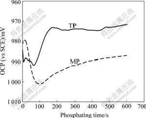
Fig.1 Changes of OCP for TP and MP with phosphating time
Compared with TP, the evolution of the OCP for MP is changed markedly. The OCP-time curve can be separated into four segments as follows: the OCP is shifted 1) towards a positive potential slightly from the initial value for a short time, 2) in a negative direction for a large extent, 3) towards a positive potential gradually, and 4) the OCP becomes stable gradually.
Due to the presence of molybdate in the modified zinc phosphate solution, phosphomolybdic heteropoly acid that is complicated and strongly oxidative is formed. Contacting HDG steel with the modified zinc phosphate solution, partial sites on MP are passivated, resulting in a slight shift of the OCP towards a positive value.
SEM and EDS results show that zinc phosphate crystals can be nucleated on MP and TP within a very short time (such as 2 s)[16]. Therefore, the negative shifts of potential approximately correspond to the rapid germination and growth of zinc phosphate crystals. Because the zinc phosphate crystals preferentially nucleate at the micro-cathodic sites on zinc surfaces [17-18], the active points of cathode are covered firstly, resulting in that the cathodic process is suppressed and the OCP is shifted in a negative direction for a period less than 100 s. When sodium molybdate is added in a traditional zinc phosphate solution, the nucleation of zinc phosphate crystals may be increased and the cathodic process is suppressed more intensively, leading to the shift of the OCP towards a more negative potential.
With the deposition of zinc phosphate, the coverage of ZPC is increased; the anodic active area of zinc is markedly reduced and the dissolution of zinc becomes slower. Therefore, the anodic process is suppressed gradually, leading to the positive shift of the OCP gradually too.
In the last stage of phosphating, most zinc surfaces are covered with zinc phosphate crystals, and the anodic process (dissolution of zinc) and cathodic process (hydrogen evolution and leading to an increase of pH value) are suppressed together. So the OCP eventually tends to be stable.
Fig.2 shows the mass gain for TP and MP as a function of phosphating time. The evolutions of the mass gain for TP and MP during phosphating are similar. The mass gain is almost proportional to time in the initial stage of phosphating, and then increases slowly and finally turns to decrease. The time for the proportional increase is approximately in accordance with that for the negative shift of the OCP. The mass gains for TP and MP are nearly equal within the initial phosphating for 60 s. Subsequently it slows down for TP, whereas keeps linear increasing for MP up to 120 s, resulting in a remarkably greater mass gain for MP than that for TP. The degree of the mass loss for MP is smaller than that for TP at the final stage of phosphating.
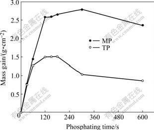
Fig.2 Changes of mass gain for TP and MP with phosphating time
3.2 Morphology of ZPC
SEM micrographs (at low magnification) of TP and MP phosphated for different time are shown in Fig.3. The coverage of both the modified and the traditional ZPC increases with phosphating time. However, compared with the traditional ZPC on TP, the nucleation of zinc phosphate crystals on MP is increased observably, and the grains on MP are finer and more compact. The grain sizes measured on MP are less than 20 μm, while those on TP are more than 50 μm.
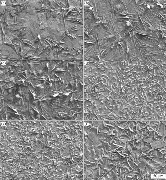
Fig.3 SEM micrographs at low magnification of TP phosphated and MP phosphated different time: (a) TP, 30 s; (b) TP, 60 s; (c) TP, 600 s; (d) MP, 30 s; (e) MP, 60 s; (f) MP, 600 s
Zinc phosphate crystals on TP are bulk needles. On MP they are fine and needle-shaped at low magnification, while at higher magnification a great part of zinc phosphate crystals are flaky and a few are needle-shaped, as shown in Fig.4. Furthermore, the bulky zinc phosphate crystals on TP can not overlap each other, while the fine zinc phosphate crystals on MP can overlap each other.
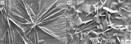
Fig.4 Morphologies of zinc phosphate crystals on TP and MP phosphated for 30 s: (a) TP; (b) MP
The mass gain of the bulky and sparse zinc phosphate crystals on TP may approach to that of the fine and compact zinc phosphate crystals on MP at the same phosphating time. However, the interspaces among zinc phosphate crystals on TP and MP are different obviously; and the porosity on MP is apparently less than that on TP.
XRD results show that ZPC on both TP and MP are mainly composed of Zn3(PO4)2・4H2O (Hopeite). The amount of molybdate added in a traditional zinc phosphate solution is little. Therefore, it is difficult to determine the presence of molybdenum on the modified ZPC by XRD.
3.3 Corrosion resistance of ZPC
Potentiodynamic polarization curves and EIS Nyquist plots of TP and MP phosphated for different time are shown in Figs.5 and 6, respectively.
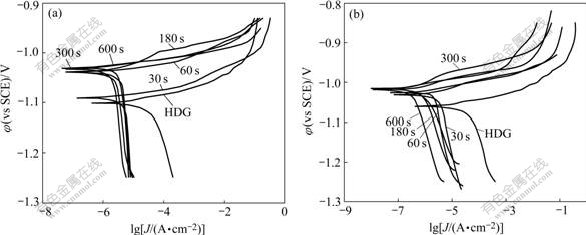
Fig.5 Potentiodynamic polarization curves of TP and MP phosphated for different time: (a) TP; (b) MP
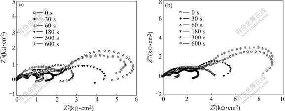
Fig.6 Impedance diagrams of TP and MP phosphated for different time: (a) TP; (b) MP
As shown in Fig.5, for a short phosphating time (30 s), the cathodic branches on the polarization curves of TP and MP are moved markedly towards the direction where the corrosion current density decreases. This may be ascribed to that zinc phosphate crystals preferentially nucleate at the micro-cathodic active sites[17-18], resulting in the first coverage of the cathodic active sites. Subsequently, the cathodic branches are changed slightly with the increase in phosphating time. The anodic branches on both TP and MP at all time move stably in the direction where the current density decreases. This is in agreement with the analysis of the OCP evolution in section 3.1.
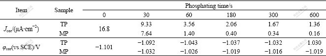
The corrosion potential and current density determined by extrapolating the anodic and cathodic Tafel lines for TP and MP (in Fig.5) are listed in Table 2. At the same phosphating time, the corrosion potential of MP is more positive than that of TP, and the corrosion current density of MP is also markedly less than that of TP, indicating the remarkable enhancement of corrosion protection ability of the modified ZPC for HDG steel.
Table 2 Corrosion potential and current density obtained from Fig.5
As shown in Fig.6, the diagram for non-phosphated HDG sample is composed of three parts: 1) high frequency capacitive loop, 2) low frequency capacitive loop, and 3) low frequency inductive loop. In a chloride environment, the corrosion products of zinc hydroxychlorides are formed on the zinc layers[19]. The high frequency capacitive loop (first) can be attributed to the formation of zinc corrosion products, which imparts the resistance to the charge transfer process. The low frequency capacitive loop (second) can be ascribed to the diffusion of the electrolyte in the pores of the corrosion products. And the low frequency inductive loop (third) can be attributed to the dissolution of zinc[20]. A similar pattern of inductive loop was also observed for electrodeposited and hot dip galvanized zinc in 0.5 mol/L sodium sulphate solution[20].
It is shown in Fig.6 that the resistance values of TP and MP phosphated for 30 s are higher than that of the non-phosphated HDG sample. The difference between resistance values is due to the formation of zinc phosphate crystals after 30 s phosphating, resulting in the decreases of the active area on TP and MP surfaces, compared with that of the non-phosphated HDG sample.
The resistance values of both TP and MP increase with phosphating time. However, the increase of the resistance values is unconspicuous for phosphating time longer than 300 s. At the same phosphating time, the resistance values of MP are markedly larger than those of TP, indicating that the corrosion resistance of MP is more outstanding than that of TP. The low frequency inductive loop on MP phosphated for 60 s almost disappears, while on TP it disappears for phosphating time up to 300 s, suggesting that for a short phosphating time the dissolution of zinc on MP is suppressed more intensively than that on TP.
The corrosion resistance of phosphate coatings is correlated with their porosity intimately. It is thus necessary to measure the porosity of phosphate coatings. According to NOTTER et al[21], to determine the porosity of ZPC by linear polarization method, the following two conditions must be satisfied: 1) compared with the substrate, the polarization current of the coatings is negligible, and 2) no passivation phenomena take place on the substrate in the test solution. ZPC are insulating and will be not involved in the electrochemical dissolution of zinc substrate; and zinc substrate can not be passivated in the neutral sodium chloride solution. Thus the experimental conditions have met the above two requirements for determining the porosity of phosphate coatings by linear polarization method. The corresponding equation can be expressed as follows:

where ΔI/ΔE is the reciprocal value of the polarization resistance in the linear range, K is a constant, ba and bc are the Tafel constants of anodic and cathodic polarization, respectively, κ represents the porosity of the coatings, stated as κ=Aa/(Aa+Ac), Aa is the exposed area of zinc substrate at the button of the pores within ZPC, and Ac is the cathodic(ZPC) area.
The porosity of ZPC determined by linear polarization method is exhibited as a function of phosphating time, as shown in Fig.7. The porosities of ZPC on both TP and MP decrease with increasing the phosphating time. While longer than 300 s the change of the porosity of ZPC is little. At the same phosphating time, the porosity on MP is less than that on TP. The addition of sodium molybdate in a traditional zinc phosphate solution decreases the porosity of ZPC remarkably. Phosphating for 600 s, the porosity on TP is about 6.2%, whereas on MP it is approximately 0.8%.
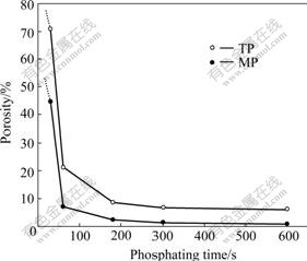
Fig.7 Curves of phosphating time vs porosities of ZPC on TP and MP
3.4 Comparison of corrosion resistance between several coatings on HDG steel
As is well-known, hexavalent chromate post- treatment is an economical and effective measure to improve the corrosion resistance of HDG steel. However, hexavalent chromium (Cr6+) is now associated with concerns about its toxic and carcinogenic nature. Recently, alternatives for chromium-free conversion coatings were broadly developed. It is thus interesting to compare the corrosion resistances between molybdate modified ZPC and chromate passivation coatings. The HDG steel is immersed in a chromate solution (2.0 g/L Na2Cr2O7) at 32 ℃ for 30 s and dried naturally, which is widely applied to passivation for batch hot dip galvanizing.
Fig.8 shows the potentiodynamic polarization curves and EIS Nyquist plots of MP and TP phosphated for 300 s and the non-treated HDG steel(HDG) and the HDG steel immersed in the above chromate solution (Cr). As shown in Fig.8(a), the corrosion current density of TP is one order smaller in magnitude than that of HDG. But that of MP is one order smaller in magnitude than that of TP and almost approaches to that of Cr, which is about 0.15 μA/cm2. As shown in Fig.8(b), the resistance values increase in the following order: HDG<TP<MP<Cr, and that of MP is also close to that of Cr. It is thus considered that the corrosion protection ability of molybdate modified ZPC on HDG steel approaches to that of the chromate conversion coatings.
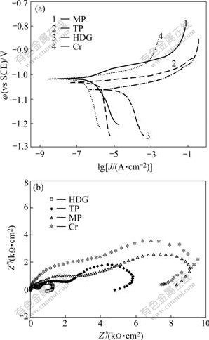
Fig.8 Polarization curves (a) and EIS Nyquist plots (b) for different conversion coatings on HDG steel
4 Conclusions
1) A modified zinc phosphate conversion coatings with different morphology and enhanced corrosion resistance are formed on HDG steel when 1.0 g/L sodium molybdate was added to a traditional zinc phosphate solution.
2) The nucleation of zinc phosphate crystals on the modified zinc phosphate conversion coatings is increased; the structure of zinc phosphate crystals is changed from bulk needles to fine flake; and a more compact coating is obtained.
3) The coverage and mass gain of zinc phosphate coatings are also increased. The corrosion resistance of zinc phosphate conversion coatings is increased with the increases in their coverage.
4) The corrosion protection ability of the modified zinc phosphate conversion coatings that are environmentally acceptable for HDG steel is more outstanding than that of the traditional zinc phosphate conversion coatings and almost approaches to that of the chromate conversion coatings.
References
[1] Akhtar A S, Susac D, Glaze P, Wong K C, Mitchell K A R. The effect of Ni2+ on zinc phosphating of 2024-T3 Al alloy [J]. Surface and Coatings Technology, 2004, 187(2/3): 208-215.
[2] Jegannathan S, Sankara Narayanan T S N, Ravichandran K, Rajeswri S. Formation of zinc-zinc phosphate composite coatings by cathodic electrochemical treatment [J]. Surface and Coatings Technology, 2006, 200(12/13): 4117-4126.
[3] Li G Y, Lian J S, Niu L Y, Jiang Z H. A zinc and manganese phosphate coating on automobile iron castings [J]. ISIJ International, 2005, 45(9): 1326-1330.
[4] Kropacheva O I, Devyatkina T S, Skornyakova N A, Saunina S I. Deposition and properties of phosphate coatings on galvanized steel [J]. Zashchita Metallov, 2003, 39(4): 367-370.
[5] Song Y K, Mansfeld F. Development of a molybdate- phosphate-silane-silicate(MPSS) coating process for electro- galvanized steel [J]. Corrosion Science, 2006, 48(1): 154-164.
[6] Jegannathan S, Sankara Narayanan T S N, Ravichandran K, Rajeswari S. Performance of zinc phosphate coatings obtained by cathodic electrochemical treatment in accelerated corrosion tests [J]. Electrochimica Acta, 2005, 51(2): 247-256.
[7] Wolpers M, Angeli J. Activation of galvanized steel surfaces before zinc phosphating―XPS and GDOES investigation [J]. Applied Surface Science, 2001, 179(1/4): 281-291.
[8] Zimmermann D, Munoz A G, Schultze J W. Formation of Zn-Ni alloys in the phosphating of Zn layers [J]. Surface and Coatings Technology, 2005, 197(2/3): 260-269.
[9] Vukasovich M S, Farr J P G. Molybdatein corrosion inhibition―A review [J]. Materials Performance, 1986, 25(5): 9-18.
[10] Kunitsugu A. Inhibition effects of chromate-free, anion inhibitors on corrosion of zinc in aerated 0.5 M NaCl [J]. Corrosion Science, 2001, 43(3): 591-604.
[11] LU Jin-tang, KONG Gang, CHEN Jin-hong, XU Qiao-yu, SUI Run-zhou. Growth and corrosion behavior of molybate passivation film on hot dip galvanized steel [J]. Trans Nonferrous Met Soc China, 2003, 13(1): 145-48.
[12] Wilcox G D, Gabe D R. Chemical molybdate conversion treatments for zinc [J]. Metal Finishing, 1988, 86(9): 71-74.
[13] Li G Y, Niu L Y, Lian J S, Jiang Z H. A black phosphate coating for C1008 steel [J]. Surface and Coatings Technology, 2004, 176(2): 215-221.
[14] Saliba-Silva A M, De Oliveira M C L, Costa I. Effect of molybdate on phosphating of Nd-Fe-B magnets for corrosion protection [J]. Materials Research, 2005, 8(2): 147-150.
[15] Freeman D B. Phosphating and Metal Pre-Treatment [M]. New York: Industrial Press, 1986.
[16] LIN Bi-lan, KONG Gang, LU Jin-tang, CHE Chun-shan, LIU Jun. Study of growth and corrosion resistance of zinc phosphate conversion coatings on hot dip galvanized steel [J]. The Chinese Journal of Nonferrous Metals, 2007, in Press. (in Chinese)
[17] Sun X, Susac D, Li R Y, Foster T, Mitchell K A R. Some observations for effects of copper on zinc phosphate conversion coatings on aluminum surfaces [J]. Surface and Coatings Technology, 2002, 155(1): 46-50.
[18] Susac D, Sun X, Li R Y, Wong K C, Wong R C, Mitchell K A R, Champaneria R. Microstructural effects on the initiation of zinc phosphate coatings on 2024-T3 aluminum alloy [J]. Applied Surface Science, 2004, 239(1): 45-59.
[19] Amirudin A, Thierry D. Corrosion mechanisms of phosphated zinc layers on steel as substrates for automotive coatings [J]. Progress in Organic Coatings, 1996, 28(1): 59-76.
[20] Cachet C, Ganne F, Joiret S, Maurin G, Petitjean J, Vivier V, Wiart R. EIS investigation of zinc dissolution in aerated sulphate medium (Part II): Zinc coatings [J]. Electrochimica Acta, 2002, 47(21): 3409-3422.
[21] Notter I M, Gabe D R. Polarisation resistance methods for measurement of the porosity of thin metal coatings [J]. Corrosion Science, 1993, 34(5): 851-870.
Corresponding author: LU Jin-tang; Tel/Fax: +86-20-85511540; E-mail: mcjtlu@scut.edu.cn
(Edited by HE Xue-feng)

