
Micro electrical discharge machining of small hole in TC4 alloy
LI Mao-sheng(李茂盛)1, 2, CHI Guan-xin(迟关心)2, WANG Zhen-long(王振龙)1, 2,
WANG Yu-kui(王玉魁)2, DAI Li(戴 立)1, 2
1. Key Laboratory of Micro-Systems and Micro-Structures Manufacturing of Ministry of Education, Harbin Institute of Technology, Harbin 150001, China;
2. School of Mechatronics Engineering, Harbin Institute of Technology, Harbin 150001, China
Received 10 June 2009; accepted 15 August 2009
Abstract: Aiming at machining deeply small holes in TC4 alloy, a series of experiments were carried out on a self-developed multi-axis micro electrical discharge machining (micro-EDM) machine tool. To improve machining efficiency and decrease relative wear of electrode in machining deeply small hole in TC4 alloy, many factors in micro-EDM, such as polarity, electrical parameters and supplying ways of working fluid were studied. Experimental results show that positive polarity machining is far superior to negative polarity machining; it is more optimal when open-circuit voltage, pulse width and pulse interval are 130 V, 5 μs and 15 μs respectively on the self developed multi-axis micro-EDM machine tool; when flushing method is applied in micro-EDM, the machining efficiency is higher and relative wear of electrode is smaller.
Key words: TC4 alloy; micro electrical discharge machining; deeply small hole; multi-axis micro-EDM machine tool
1 Introduction
Ti alloy is an important structural metal developed in 1950s. Because of its remarkable mechanical and chemical properties such as high specific strength, good corrosion resistance, high melting temperature, stable performance at moderate temperatures and other excellent properties, Ti alloy, which is known as a light-weight metal material in the 21st century, is paid more and more attention to in aircraft, atomic energy, ocean development and medical device[1-7]. From this point of view, machining Ti and its alloy present great importance[8]. Thereinto, machining deeply small hole in Ti alloy is a hot issue today. However, because Ti alloy possesses low heat conductivity and very strong toughness, its cutting performance is poor. Especially, when small hole in Ti alloy is machined by traditional machining method, drill bit is easily broken and machining efficiency is very low because of low rigidity and difficult to be evacuated[9]. Because untouched machining characteristic EDM has superiority to small hole machining, any conductive material with any hardness can be machined by EDM. Blind hole, deep hole, inclined hole and profiled hole can be machined[10]. In addition, because surface machined by EDM has a series of discharge caves and there is no spiral trace obtained by ordinary drilling processing, flow field distribution of liquid or gas flowing through small holes can be improved greatly. So, EDM can be used as an effective means for small hole machining in some special applications[7]. In this work, according to the characteristics of TC4 alloy, a lot of experiments for small holes machining in TC4 alloy were carried out on a self-developed multi-axis micro-EDM machine tool. The effects of polarity, electrical parameters and supplying ways of working fluid on machining efficiency and relative wear of electrode were analyzed. Furthermore, corresponding process rules were summarized.
2 Experimental
2.1 Basic characteristics of TC4 alloy
Ti-6Al-4V, containing aluminum and vanadium, is a typical martensite α+β two-phase Ti alloy[11]. It is of low conductivity, high strength and high hardness, and belongs to the densest hexagonal crystal structure. At present, Ti-6Al-4V alloy has become an international Ti alloy. Various Ti alloys are produced all over the world. In China, Ti-6Al-4V alloy occupies the main position and is named as TC4. Its compositions and physical performances are shown in Tables 1 and 2, respectively.
Table 1 Compositions of TC4 alloy[12] (mass fraction, %)
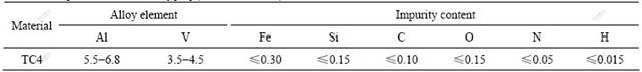
Table 2 Physical performances of TC4 alloy[13]
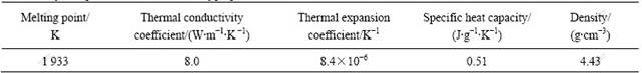
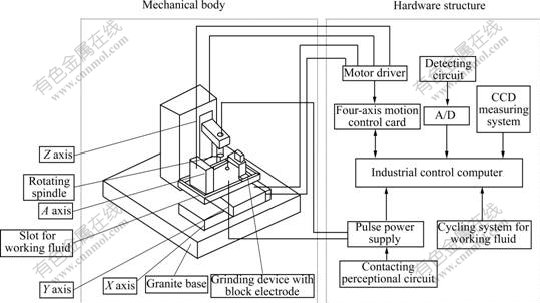
Fig.1 Schematic diagram of multi-axis micro-EDM machine tool
2.2 Experimental equipment
A self-developed multi-axis micro-EDM machine tool is used and the schematic diagram is shown in Fig.1. It mainly consists of granite base, three-axis linear platform of X, Y and Z, A-axis rotary table, rotary spindle, grinding device with block electrode, transistor-RC compound pulse power supply, and CCD displaying device. On the one hand, other parts are set on the granite base; on the other hand, the granite base used as a connecting part is set on the platform of electrical control cabinet to decrease discrete capacitance of the whole equipment and insulate other parts. X and Y linear platforms drive workpeices set in a working-fluid slot to move arbitrarily on the XY plane together and the Z linear platform drives an electrode clamped by the rotary spindle feed and turn back in Z-axis direction. The A-axis rotary table is used to rotate workpeices at any angle. The grinding device with block electrode is used to fabricate micro-thin electrode on line. The transistor-RC compound pulse power supply is used to generate high-frequency pulse for micro-EDM. The CCD displaying device is used to observe figuration and dimension of electrode and small hole.
2.3 Foundational conditions
The foundation conditions are as follows: equipment, multi-axis micro-EDM machine tool; electrode, red copper and Cu-W alloy electrode of d0.5 mm in diameter; workpeices, TC4 plates (20 mm×100 mm×3 mm); working fluid, special EDM kerosene; supplying ways of working fluid, flushing/dipping; polarity, positive polarity/negative polarity; high voltage; servo voltage, 100 V; open-circuit voltage, 90/130 V; tool lifting height, 1 mm; tool lifting period, 5 s.
3 Results and discussion
3.1 Machining surface analysis
In Ref.[14], it was described that hole-wall roughness of deeply small hole in Ti alloy machined by EDM is generally small. Machining performance for Ti alloy is good in single-pulse discharge machining experiment, but machining velocity is decreased in continuous-pulse discharge machining experiment while electrode wear is increased. It is the reason for that flanging of discharging caves in Ti alloy machining is larger and flanging time is longer. Machining chips of high-speed steel and Ti alloy are shown in Fig.2. It is seen that machining chips of steel are almost in regular shape, but most of machining chips in machining Ti alloy are deformed into fragment shape.
This shows that in machining steel removal metal is melted or vaporized completely; and once it is solidified; newly regular shape is formed under the influence of metal surface tension. But the machining Ti alloy is not melted completely because of lower thermal conductivity. Therefore, throwing process of machining chip is not ideal and flanging is easily formed at the inlet position of small hole. Based on the above analysis and improved pulse power supply, the following experiments are carried out.
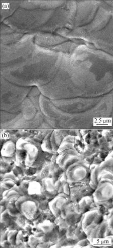
Fig.2 FEM images of machining chips: (a) High speed steel; (b) Ti alloy
3.2 Effect of polarity on machining efficiency and relative wear of electrode
Fig.3 shows a histogram of polarity to machining efficiency and relative wear of electrode obtained by changing polarity when small holes are machined in a TC4 plate with 3 mm in thickness by Cu-W electrode with d0.5 mm in diameter. Other machining parameters are shown in Table 3.
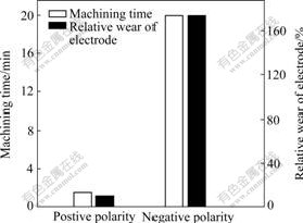
Fig.3 Polarity-machining efficiency and relative wear of electrode histogram
Table 3 Machining parameters
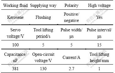
Fig.3 shows that machining efficiency is far higher in positive polarity machining than in negative polarity machining, and relative wear of electrode is far lower in positive polarity machining than in negative polarity machining. It can be explained by that during short-pulse machining bombarding the effect of electrons on surface of positive polarity is greater than bombarding effect of ions on surface of negative polarity, and the effect of energy distribution on the positive polarity is more serious than that on the negative polarity. So, when positive polarity machining is applied, a larger removal rate and a smaller electrode wear are obtained. Therefore, the machining efficiency in positive polarity machining is higher and the relative wear of electrode is smaller.
3.3 Effect of electrical parameters on machining efficiency and relative wear of electrode
3.3.1 Effect of open-circuit voltage on machining efficiency and relative wear of electrode
Curves of open-circuit voltage on machining efficiency and relative wear of electrode are shown in Fig.4 under the condition that red-copper electrode of d0.5 mm in diameter is used to machine small holes in a TC4 plate with 3 mm in thickness. Surface topographies of small holes at different open-circuit voltages are illustrated in Fig.5.
It is known in Fig.4 that machining efficiency is higher in higher open-circuit voltage than that in lower open-circuit voltage, and relative wear of electrode is larger in higher open-circuit voltage than that in lower open-circuit voltage under different capacitances.
The research results show that single pulse discharge energy (WM) can be expressed by the following equation[15]:
 (1)
(1)
where te is actual discharge time of single pulse; u(t) and i(t) are voltage and current in discharge gap, and changed with time, respectively.
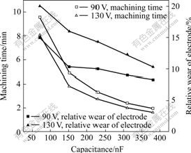
Fig.4 Effect of open-circuit voltage on machining efficiency and relative wear of electrode
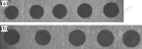
Fig.5 Surface shape of holes machined under different capacitances at two open-circuit voltages: (a) 90 V; (b) 130 V
From Eq.(1), it is known that as open-circuit voltage increases single pulse discharge energy increases, so that discharge bombarding force is stronger and material removal effect is larger and finally the machining efficiency is higher. EDM material removal rates of positive and negative polarities are proportional to single pulse discharge energy. When the open-circuit voltage is increased from 90 to 130 V, electrode wear is enlarged to a certain extent and material removal rate is constants so that relative wear of electrode is enlarged.
Holes in Fig.5(a) are machined at different capacitances and 90 V, and those in Fig.5(b) are machined at different capacitances and 130 V. The capacitance increases from left to right. It is known that as capacitance increases, the discharge gap and the hole diameter increase, but roundness of small holes is better. At the same time, the hole diameter is larger at 130 V.
3.3.2 Effect of pulse width on machining efficiency and relative wear of electrode
Curves of pulse width vs machining efficiency and relative wear of electrode by changing pulse width are shown in Fig.6 under the condition that red copper and Cu-W electrodes of d0.5 mm in diameter are applied to machining small holes in a TC4 plate of 3 mm in thickness. It is known that no matter which electrode is used to machine TC4 alloy the machining efficiency increases firstly and then decreases as pulse width increases. Before 5 μs machining efficiency increases a little and after 5 μs machining efficiency decreases rapidly. Machining efficiency is optimal when the pulse width is about 5 μs. Relative wear of electrode increases. Before 20 μs velocity increases quickly and slows down after 20 μs.
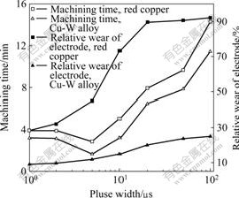
Fig.6 Effect of pulse width on machining efficiency and relative wear of electrode
When short pulse width is used, the phenomenon that a lot of electrons with negative charge in discharge channel bombard positive polarity is obvious[16]. From Eq.(1), as pulse width increases, single pulse energy increases gradually. Therefore, material removal rate increases and machining efficiency is improved. As pulse width increases further, current density in discharge channel decreases, so that utilization of pulse energy and material removal rate decrease. In addition, as pulse width increases, duty cycle increases, chip removal is not good, discharge status is not stable and finally machining efficiency decreases. When pulse width is moderate, pulse energy is higher for melting metal than for boiling metal. Pulse density in discharge channel is not decreased greatly because the discharge channel is enlarged, and pulse energy can be made full use of. As pulse width increases, the phenomenon that ions in discharge channel bombard negative polarity becomes obvious and electrode wear increases. In addition, as pulse width increases duty cycle increases, chip-removal condition is poor and deionization becomes inadequate, so relative wear of electrode increases gradually. When pulse width increases to a certain extent, ranges of pulse energy, discharge bombarding force and chip-removal condition decrease, and relative wear of electrode becomes steady.
3.3.3 Effect of pulse interval on machining efficiency and relative wear of electrode
Curves of pulse interval vs machining efficiency and relative wear of electrode are shown in Fig.7 under the condition that red copper and Cu-W electrode of d0.5 mm in diameter are used to machine small holes in a TC4 plate of 3 mm in thickness.
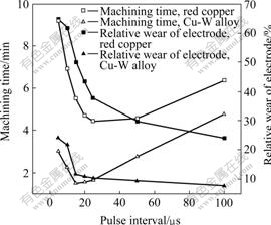
Fig.7 Pulse interval on machining efficiency and relative wear of electrode curves
As illustrated in Fig.7, when pulse interval increases, machining efficiency increases rapidly and then decreases slowly and the tendency of relative wear of electrode is the same. The machining efficiency reaches the maximum value at 15 μs or so. The reason for this is that under the condition that open-circuit voltage, peak current, capacitance and pulse width are constant, as pulse interval increases, duty cycle decreases gradually, working condition between polarities becomes good, deionization becomes adequate, chip removal is good, discharge status is stable and utilization of electrical energy becomes high. So, machining efficiency increases gradually. When pulse interval increases to a certain extent, the working status between polarities becomes steady, but the duty cycle decreases so that available discharge time decreases relatively and single pulse energy decreases to decrease material removal rate and machining efficiency gradually. As pulse interval increases, single pulse energy decreases and duty cycle decreases so that working status and relative wear of electrode become good and steady gradually.
3.4 Effect of supplying way of working fluid on machining efficiency and relative wear of electrode
The effect of supplying way of working fluid on machining efficiency and relative wear of electrode by changing pulse intervals are shown in Fig.8 under the condition that red copper and Cu-W electrode of d0.5 mm in diameter are used to machine small holes in a TC4 plate of 3 mm in thickness.
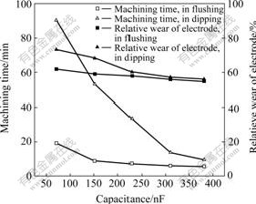
Fig.8 Effect of supplying way of working fluid on machining efficiency and relative wear of electrode
Fig.8 shows that machining efficiency is higher in flushing than in dipping. Change tendency of relative wear of electrode is the same and relative wear of electrode in flushing is smaller. The reason for this is that in dipping the free carbon content is higher and it is easy to form titanium carbide. So, discharge status is unsteady, machining efficiency is low and relative wear of electrode is great. In flushing the carbon decomposed from kerosene can be carried away by working fluid instantly so that less free carbon reacts with titanium to form titanium carbide, the discharge status is steady, the machining efficiency is high and the relative wear of electrode is small.
4 Conclusions
1) When short pulse is used to machine small holes in TC4 alloy, positive polarity machining is far superior to negative polarity machining in machining efficiency and relative wear of electrode.
2) Electric parameters have various influences on machining efficiency and relative wear of electrode and machining efficiency is incompatible to relative wear of electrode. Therefore, moderate electric parameters should be applied to giving attention to machining efficiency and relative wear of electrode. It is more optimal that open-circuit voltage, pulse width and pulse interval are 130 V, 5 μs and 15 μs respectively on the self-developed multi-axis micro-EDM machine tool.
3) When small hole is machined in TC4 alloy, machining efficiency and relative wear of electrode in flushing are superior.
References
[1] GAO Hong-ming, BAI Yan, YANG Tian-dong. Double-sided gas tungsten arc welding process on TC4 titanium alloy[J]. Trans Nonferrous Met Soc China, 2005, 15(5): 1081-1084.
[2] SUN Zhong-gang, HOU Hong-liang, LI Hong. Effect of hydrogen treatment on microstructure and room temperature deforming properties of TC4 alloy[J]. The Chinese Journal of Nonferrous Metals, 2008, 18(5): 789-793. (in Chinese)
[3] SONG Hui, WANG Zhong-jin, GAO Tie-jun. Effect of high density electropulsing treatment on formability of TC4 titanium alloy sheet[J]. Trans Nonferrous Met Soc China, 2007, 17(1): 87-92.
[4] YANG Y L, ZHAO G J, ZHANG D. Improving the surface property of TC4 alloy by laser nitriding and its mechanism[J]. Acta Metall Sin, 2006, 19(2): 151-156.
[5] JIANG Zhao-hua, YAO Zhong-ping, LI Yan-ping. Effect of phosphate on structure and anticorrosive properties of ceramic film grown on Ti alloy by micro-plasma oxidation[J]. Materials Science and Technology, 2004, 12(1): 75-79. (in Chinese)
[6] WANG Ya-ming, LEI Ting-quan, JIANG Bai-ling. Ceramic coating formed on Ti6Al4V alloy by micro-arc oxidation in Na2SiO3- KOH-(NaPO3)6 solution[J]. Rare Metal Materials and Engineering, 2003, 32(12): 1041-1044.
[7] WANG Zhen-long, CHI Guan-xin, DI Shi-chun. Micro ultrasonic EDM of deep, small holes in titanium alloys[J]. Acta Armam Entar Ⅱ, 2000, 21(4): 346-349.
[8] ALIK A H, AYDAS U C. Electrical discharge machining of titanium alloy (Ti-6Al-4V)[J]. Applied Surface Science, 2007, 253(5): 9007-9016.
[9] GUO Hong-qin, PEI Jing-yu, LI Wu-yi. Process study of micro hole in EDM[J]. Aerospace Manufacturing Technologies, 2005(5): 16-18.
[10] ZHU Yu-hua, WEI Hong-yu, ZHAO Wan-sheng. Researches on small deep hole machining on titanic alloy with EDM[J]. Electromachining and Mould, 2006(3): 38-41.
[11] LUO Jiao, LI Miao-quan, LI Hong. High temperature deformation behavior of TC4 titanium alloy and its flows stress model[J]. The Chinese Journal of Nonferrous Metals, 2008, 18(8): 1395-1401. (in Chinese)
[12] WANG Jin-you. Titanium alloy for aviation[M]. Shanghai: Shanghai Science and Technology Press, 1985: 91-92.
[13] QIANG Hua, ZHANG Yong, HUANG Nan. Discussion of electrode loss during machining process of TC4 alloy by EDM[J]. New Technology and New Process, 2006(10): 18-19. (in Chinese)
[14] WEI Hong-yu. Study of processing mechanism and process for EDM micro shaft and hole by WEDG[D]. Harbin: Harbin Institute of Technology, 1999. (in Chinese)
[15] ZHAO Wan-sheng. Advanced electrical discharge machining technology[M]. Beijing: National Defense Industry Press, 2003: 13-24. (in Chinese)
[16] WANG Zhen-long, ZHAO Wan-sheng. Research on the erosion process of electrode materials in micro-EDM[J]. Mechanical Science and Technology, 2002, 12(1): 124-126. (in Chinese)
(Edited by CHEN Wei-ping)
Foundation item: Project (2006AA04Z323) supported by High-tech Research and Development Program of China
Corresponding author: LI Mao-sheng; Tel: +86-451-86416323; E-mail: hitedm200509@163.com

