
Effects of sintering pressure and temperature on microstructure and tribological characteristic of Cu-based aircraft brake material
XIONG Xiang(熊 翔), SHENG Hong-chao(盛洪超), CHEN Jie(陈 洁), YAO Ping-ping(姚萍屏)
State Key Laboratory of Powder Metallurgy, Central South University, Changsha 410083, China
Received 22 September 2006; accepted 30 November 2006
Abstract: A novel Cu-based P/M aircraft brake material was prepared and the effects of sintering pressure and temperature on microstructure and tribological characteristic were investigated. For the constant sintering temperature, when the sintering pressure increases from 0.5 MPa to 1.5 MPa, the porosity, wear loss and friction coefficient decrease remarkably. When the sintering pressure increases from 1.5 MPa to 2.5 MPa, the porosity further decreases but in a little degree and wear behaviors are improved slightly. However, once the sintering pressure is larger than 2.5 MPa, it has no obvious effect on microstructure and tribological characteristic. For the constant sintering pressure, when the sintering temperature increases from 900 ℃ to 930 ℃, the sintered density remarkably increases, and wear behaviors are obviously improved. For further increasing sintering temperature to 1 000 ℃, the density keeps on increasing, but wear behaviors change slightly.
Key words: P/M friction materials; sintering pressure; sintering temperature
1 Introduction
Powder metallurgy(P/M) friction materials are the composites made up of metal matrixes, friction components and solid lubricants. These materials are normally classified into three types according to the matrixes, namely Cu-based, Fe-based and Cu-Fe-based materials[1-2]. Compared with Fe-based and Cu-Fe- based materials, Cu-based materials have many advantages, such as better heat conductivity and friction resistance, so they are broadly used in aircrafts, automobiles and shipping brake systems[3-4].
In the past several decades, many studies had focused on the sintering techniques of Cu-based aircraft brake materials. However, with the rapid development of aeronautical industry, the mass of aircrafts keeps on increasing and brake speed increases remarkably, which results in the notable enhancement in brake energy. For example, the friction surface temperature is usually above 1 000 ℃ and the bulk temperature also can be 600℃. Therefore, for the present working condition, the components and the preparation of brake materials have greatly changed. However, domestic studies on the new type of aircraft brake materials have been limited. In the present study, the effects of sintering pressure and temperature on microstructure and tribological characteristic of a new type Cu-based aircraft brake materials were studied thoroughly.
2 Experimental
2.1 Sample preparation
The powders listed in Table 1 were weighed with given proportion, well blended and compacted in a steel die. The compacts were subsequently sintered for 3-4 h in a pressed bell furnace saturated with dry H2 at 900- 1 000 ℃ and pressure of 0.5-4.5 MPa. The sintered materials were then driven out when the water-cooled temperature is lower than 100 ℃.
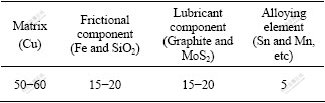
Table 1 Chemical composition of Cu-based friction materials (mass fraction, %)
2.2 Test and analysis
The densities of sintered compacts were measured according to ASTM B376―65 [5]. The microstructures were investigated by optical metallographic microscope (OM) and scanning electron microscope(SEM). In OM, the erode liquor is saturated FeCl3 contained in alcohol.
The friction and wear property test were carried out on an MM-1000 type tester with 30CrMoSiVA structural steel (HRC 40) as counterpart. The samples were machined into rings with circumradius and inradius of 75 mm and 53 mm, respectively. The relative parameters were load of 0.8 MPa, inertia of 2.5 kg?cm?s2 and the rotating rate of 6 500 r/min. Every sample was tested 10 times. The wear loss was obtained by measuring the average difference of the sample’s thickness at three different spots before and after test. According to the moment force recorded during braking, the friction coefficient can be calculated by f=M/(PR), where f is the friction coefficient, P is working load and R is sample’s radius. The average result of the last five tests was considered as the friction coefficient of this sample.
3 Results and discussion
3.1 Microstructure
Fig.1 shows the typical microstructures of compacts sintered at 930 ℃ under the pressure of 0.5, 1.5, 2.5 and 4.5 MPa, respectively. It’s found in Fig.1(a) that many evident interfaces exist among particles and pores remain in the matrix, which indicates that the sintering process is still not complete under 0.5 MPa. Under this pressure, since the shearing stress working on the material is lower than its yield strength, the densification can only be carried through by diffusion. When sintering pressure increases to 1.5 MPa, the interfaces among particles almost disappear and the pores reduce remarkably, as shown in Fig.1(b). Under this higher pressure, the shearing stress outweighs the material’s yield strength and then plastic flow of metal elements in the matrix happens, which accelerates the densification. When the sintering pressure reaches 2.5 MPa, the copper particles couple with each other (Fig.1(c)), indicating the completeness of sintering process. By comparing Fig.1(c) with Fig.1(d), it can be found the microstructure varies slightly for the further increasing pressure to 4.5 MPa, which suggests sintering pressure of 2.5 MPa is sufficient for thorough sintering process.
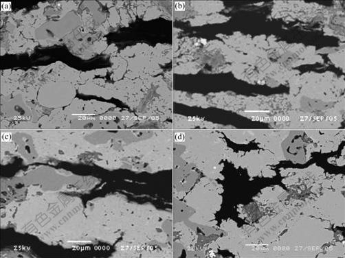
Fig.1 Microstructures of sintered compacts under different sintering pressures: (a) 0.5 MPa; (b) 1.5 MPa; (c) 2.5 MPa; (d) 4.5 MPa
Fig.2 shows the microstructures perpendicular to pressure direction of composites sintered under 2.5 MPa, at temperatures of 900, 930 and 1 000 ℃, respectively. For the sintering temperature of 900 ℃, some black spots appear in Fe particles (Fig.2(a)). SEM observation further reveals these spots are pores (Fig.3(a)). In addition, the connection of Fe and Cu is pore and some pores exist at the interfaces. Compared with this image, the pores in Fe particles reduce remarkably and the bonding strength between Fe and Cu particles improves obviously for sintering temperature of 930 ℃ (Fig.2(b) and Fig.3(b)). However, for further increasing sintering temperature to 1 000 ℃, the microstructure changes slightly, which can be found by comparing Fig.2(b) with Fig.2(c).
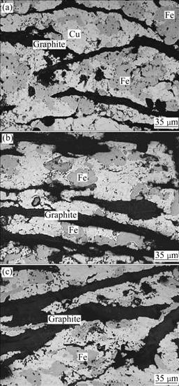
Fig.2 Microstructures of sintered compacts at different sintering temperatures: (a) 900 ℃; (b) 930 ℃; (c) 1 000 ℃

Fig.3 SEM images of Fe particles in sintered compacts: (a) 900 ℃; (b) 1 000 ℃
The diversity of composite’s microstructures with temperatures is closely related with the dissimilar sintering behaviors of components at different temperatures. The transformation of ferrite to austenite at 912 ℃ [6] enhances the solubility of Cu in Fe from about 1% to 8%, which increases the alloying degree between copper and ferro [7]. Therefore, the higher the sintering temperature, the larger the chemical interdiffusion coefficient between Fe and Cu, which causes the vacancy and dislocation in matrix to increase remarkably, accelerates the diffusion creep of material and does favor to the sintering process [8-9]. This is the main factor of pore elimination in Fe particles. When sintering temperature increases from 930 ℃ to 1 000 ℃, the sintering property of components changes slightly, and thus the corresponding microstructures hardly change.
3.2 Densification
Fig.4 shows the relationship between porosity and sintering pressure at the same sintering temperature. It can be seen that the total porosity and open porosity of samples decrease remarkably with the increase of sintering pressure from 0.5 MPa to 2.5 MPa. Once the sintering pressure is larger than 2.5 MPa, it has no obvious effect on the densification. These are consistent with the phenomena observed in Fig.1. Thus, it’s further shown that 2.5 MPa is enough for complete sintering and higher pressure has minor effect on densification.
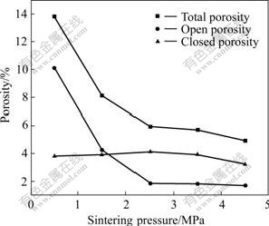
Fig.4 Relationship between porosity and sintering pressure
Besides, it also can be seen from Fig.4 that the total porosity and open porosity both show similar down-trend. However, the closed porosity changes slightly. It can be summarized that the change of total porosity is mainly aroused by the variation of open pores, and the closed pores have minor contribution on densification. More or less gas is imprisoned in the closed pores, which hinders the shrinkage of pores during sintering process [10]. Thus, the closed pores are little affected.
The relationship between porosity and sintering temperature under the same sintering pressure is shown in Fig.5. The change of porosity is classified into two stages. In stageⅠ, when the sintering temperature changes from 900 ℃ to 930 ℃, the total porosity and closed porosity both remarkably reduce, while the open porosity changes slightly. These indicate that the reduction of closed pores mainly brings about the densification of composite. By comprehensively analyzing Figs.2, 3 and 5, it can be further ascertained that the elimination of pores in Fe particles causes the densification of composite in this stage. In stageⅡ, when the sintering temperature changes from 930 ℃ to 1 000 ℃, the total porosity, closed porosity and open porosity all decrease, which reveals that the closed pores and open pores both affect the densification of composites. The reason lies in two aspects. On one hand, with the increase of sintering temperature, the sintering driving force increases and the self-diffusion and inter-diffusion of atoms enhance as well, which accelerates the densification of materials. On the other hand, due to components of low fusing point (such as Sn) in the matrix, some liquid phase will appear at higher temperature, which can fill some pores and then strengthen the densification of the composites to a certain extent.
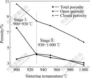
Fig.5 Relationship between porosity and sintering temperature
3.3 Tribological characteristics
Fig.6 shows the relationship between sintering pressure and friction and wear behaviors. When the sintering pressure increases from 0.5 MPa to 1.5 MPa, the friction coefficient and wear loss decrease by 14% and 28%, respectively. However, they only decrease by 4% and 8% respectively when the sintering pressure increases from 1.5 MPa to 2.5 MPa. For the sintering temperature higher than 2.5 MPa, they change slightly.
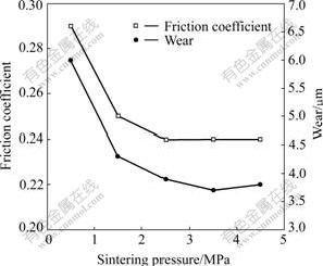
Fig.6 Relationship between sintering pressure and friction and wear behaviors
Fig.7 displays the relationship between sintering temperature and friction and wear behaviors. With the increase of sintering temperature, the friction coefficient varies slightly, which indicates that in the certain range of temperature, the change of porosity has slight effect on friction coefficient of this Cu-based friction composite. At the same time, the wear of composite is severe for the sample sintered at 900 ℃. However, the wear loss decreases remarkably for raising sintering temperature to 930 ℃ and it becomes stable for further raising sintering temperature to 1 000 ℃.
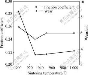
Fig.7 Relationship between sintering temperature and friction and wear behaviors
3.4 Worn surface and sub-surface
The typical worn surfaces of composites under different sintering pressures are shown in Fig.8. The worn surface of specimen sintered under 0.5 MPa takes on lots of adherences and casts and looks much rougher than that sintered under 2.5 MPa. This shows that severe wear happens between the friction material and the counterpart during sliding process, which causes higher friction coefficient and wear loss. For specimen sintered under 2.5 MPa, the worn surface is relatively integrated and only scattered pieces break off from it, which shows the specimen sintered at this temperature has favorable wear resistance(Fig.6).
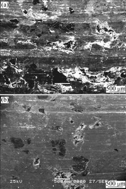
Fig.8 Micrographs of friction surfaces under different sintering pressures: (a) 0.5 MPa; (b) 2.5 MPa
Fig.9 presents the micrographs of friction surfaces along cross-section under different sintering pressures, where the black strips are flake graphite. In case of composite sintered at 0.5 MPa, the graphite array is parallel to friction direction, few is extruded to the surface as shown in Fig.9(a). However, the surface of composite sintered under 2.5 MPa is covered with a thin and integrated friction layer and the graphite has the tendency to be extruded to the friction surface, as shown in Fig.9(b).
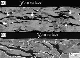
Fig.9 Micrographs of friction surface along cross-section under different sintering pressures: (a) 0.5 MPa; (b) 2.5 MPa
According to the wear theory of self-lubricant materials, lubricant components, such as graphite, will be extruded from deformation layer during sliding process [11-12]. In the materials prepared under 0.5 MPa some open pores remain, which act as channels. According to fatigue friction theory, the apt-to-slide flake graphite will extend and join with each other through the channels parallel to the friction direction, which results in the graphite’s lamination and accumulation in the sub-surface, as shown in Fig.9(a). That is to say, the graphite can hardly be extruded to the worn surface and surface lubrication is not enough. This is the main reason for higher friction coefficient and severe adhesion of composite sintered under this pressure, as shown in Fig.8.
When the sintering pressure increases from 0.5 MPa to 2.5 MPa, the porosity of composite decreases considerably and prevents the parallel prolongation of graphite, so the lamination and accumulation of graphite on the sub-surface won’t happen and graphite can be normally extruded to the surface. The extruded graphite gradually forms adherence layer with low shear intension, which effectively prevents initiation of microcracks on the worn surface. Thereby, the steady friction layer forms and prevents adhesion between the matrix and counterpart. These favor to lower the friction coefficient and wear loss [13].
Fig.10 shows the macrographs of worn surfaces of specimens sintered at different temperatures. It is found that the worn surfaces mainly involve two sections, namely smooth section and rough section. The smooth section looks darker and is integrated with little casts. In contrast, the rough section looks pale and fragmentary with lots of casts. Compared Fig.10(a) with Fig.10(b), it is also found that monolithic casts occur in a large area shell from the worn surface for composite sintered at 900 ℃, but only spot casts in a small area happen for that sintered at 1 000 ℃.
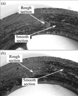
Fig.10 Macrographs of worn surfaces at different sintering temperatures: (a) 900 ℃; (b) 1 000 ℃
Cross-sectional micrographs of the smooth areas of friction surfaces at different sintering temperatures are shown in Fig.11, where the arrowhead referred is the covered friction film. For the specimen sintered at 900 ℃, the friction film is about 40 mm in thickness and contains lots of cracks, which indicates that this kind of film is easy to break during sliding process. For the specimen sintered at 930 ℃, the friction film is 10-20 mm in thickness. This kind of thin film helps to improve the wear property of composite. For the specimen sintered at 1 000 ℃, superposition of friction film is found because the new friction film has formed before the old is destructed. It further indicates that thinner friction film is not easy to break off, so it is favored to improve wear property of composite.
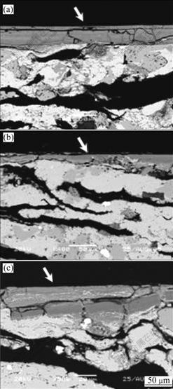
Fig.11 Cross-sectional micrographs of smooth areas of friction surfaces at different sintering temperatures: (a) 900 ℃; (b) 950 ℃; (c) 1 000 ℃
Diversity of wear property of composites at different temperatures is closely related with the microstructure, especially that of Fe particles. Fe particles also play a particle strengthening role in the composite due to its higher strength and hardness than the matrix [14]. Because many pores remain in the composite sintered at 900 ℃, as well as the weak connection between Fe and Cu, particle strengthening of Fe is weakened, which leads to lots of material avulsions along graphite and severe wear loss. During sliding, part of particles fall from the worn surface and become debris, the others accumulate in grooves or pits and further transform into friction film under the action of multi-axial stress. For the debris with large volume and quantity, the transformed friction film is thick, as shown in Fig.11(a). For the composite sintered at 930℃, the pores in Fe particles remarkably reduce and the connection between Fe and Cu becomes strong (Fig.3(b)), so the particle strengthening action of Fe particles enhances, which results in a small quantity of debris at the connection region of the material and its counterpart. This is the main reason for obvious decrease of wear loss. For the debris with small volume and size, the transformed friction film is relatively thin (Fig.11(b)), which causes the decrease of wear loss and stable brake of composite.
In addition, since the friction film on the surface directly contacts with the counterpart, it endures intense friction and thermal impact stress, which makes microcracks generate and even fall off. For the thicker friction film, this trend of falling is more obvious [11]. The thickness of friction film on the composites sintered at 900 ℃ is 2-4 times than that sintered at 930 ℃. That is one of the reasons for severe wear of composite sintered at 900 ℃.
4 Conclusions
1) At the constant sintering temperature, the porosity, wear loss and friction coefficient of composites all remarkably decrease as the sintering pressure increases from 0.5 MPa to 1.5 MPa. As the sintering pressure increases from 1.5 MPa to 2.5 MPa, the porosity and wear loss decrease slightly. Further increase of sintering pressure has little effect on microstructure and tribological characteristic of Cu-based friction materials.
2) Under the constant sintering pressure, the wear loss of composites sintered at 900 ℃ is severe. As the sintering temperature increases from 900 ℃ to 930 ℃, density and tribological characteristic of materials improve remarkably. As the sintering temperature increases to 1 000 ℃, the density further increases, but the tribological characteristics change slightly. In the temperature range of experiment, sintering temperature has minor effect on the friction coefficient.
References
[1] MILLER R A. Thermal barrier coating for aircraft engines: History and directions [J]. Thermal Spray Tech, 1997, 16(1): 35-42.
[2] FIDOLJINGEИ M, XU Run-ze. Modern friction materials [M]. Beijing: Metallurgical Industry Press, 1983.
[3] LOCKER K D. Friction materials―An overview [J]. Powder Metallurgy, 1992, 35(4): 253-255.
[4] YANG Yong-lian. Sintered metal friction materials [J]. Materials for Mechanical Engineering, 2000, 31(1): 98-99.
[5] ASTM. Density of Sintered Metal Friction Material [S]. B376-65, 1980.
[6] PAN Jin-sheng. Base of materials science [M]. Beijing: Tsinghua University Press, 2004.
[7] HUANG Pei-yun. The principle of powder metallurgy (2nd ed) [M]. Beijing: Metallurgical Industry Press, 2004.
[8] XIE Wen, LIU Yue, LI De-song. Influence of sintering routes to the mechanical properties of magnesium alloy and its composites produced by PM technique [J]. Journal of Alloys and Compounds, 2006, 23: 157-164.
[9] OLEVSKY E A, GERMAN R M. Effect of gravity on dimensional change during sintering (I): Shringkage anisotropy [J]. Acta Materialia, 2000, 48(5): 1153-1166.
[10] GUO Shi-ju. Sintering theory of powder metallurgy [M]. Beijing: Metallurgical Industry Press, 1998.
[11] MOUSTAFA S F, AEL-BADRY S, SANAD A M, KIEBACK B. Friction and wear of copper-graphite’s make with Cu-coated and uncoated graphite powders [J]. Wear, 2002, 253: 699-710.
[12] WEN Shi-zhu, HUANG-ping. The principle of tribology [M]. Beijing: Tsinghua University Press, 2002.
[13] XUE Qun-ji, LIU Hui-zhi. The tribology of ceramic(II): The lubrication of ceramic [J]. Tribology, 1996, 16(2): 65-70.
[14] FAN Yi, ZHANG Jin-sheng, WANG Ling-sen, GAO You. Effect of iron concentration on friction and wear characteristics of Cu-Fe based P/M friction materials [J]. Tribology, 1999, 19(3): 204-208.
Foundation item: Project(20050533039) supported by the Doctoral Foundation of Ministry of Education, China
Corresponding author: XIONG Xiang, Tel: +86-731-8836079; E-mail: Xiong228@sina.com
(Edited by YANG Bing)

