J. Cent. South Univ. Technol. (2010) 17: 1000-1005
DOI: 10.1007/s11771-010-0590-5

Improved model to SOLVE influence coefficients of work roll deflection
ZHAO Tie-yong(赵铁勇), XIAO Hong(肖宏)
School of Mechanical Engineering, Yanshan University, Qinhuangdao 066004, China
? Central South University Press and Springer-Verlag Berlin Heidelberg 2010
Abstract: According to the concept of virtual bending force, a rational explanation for SHOHET’s model was presented. Considering the deformation characters of the work rolls in four-high mill, the deformation model of the work roll was regarded as a cantilever beam and new influence coefficients were deduced. The effect of the bending force was taken into account independently. Therefore, the contribution to work roll deflection caused by rolling load, rolling pressure between rolls and bending force can be got from the new formulas. To validate the accuracy of the formulas, the results obtained from the new formulas were compared with those from SHOHET’s formulas. It is found that they highly coincide, which illustrates that the formulas are reliable.
Key words: work roll; influence coefficient; cantilever beam; bending force
1 Introduction
The trend of the hot strip product is toward the economical manufacture of high quality with close tolerance. The roll gap profile under the rolling load determines the strip profile after rolling (the elastic recovery of the strip is not considered). So, developing high accuracy prediction model for strip crown must be based on the high accuracy roll deformation model. The development of the roll deformation model can be divided into three groups, including simple beam model, slit beam model and finite element analysis model [1]. STONE and GRAY [2] took the roll deformation as the deflection of a simple beam on an elastic foundation. SHOHET and TOWNSEND [3] proposed a slit beam deflection model. EDWARDS and SPOONER [4] and WANG [5] improved this theory and introduced a matrix method to solve the beam deflection considering strip plastic deformation. It has now been widely used in the analysis of rolls deformation, strip shape and profile.
Although the slit beam model has its own limitations such as simple bending assumptions, this model is still the most convenient one due to its acceptable time consuming in predicting the required set point in profile and flatness control. ZHANG et al [6], GUO [7], YUN et al [8], SALINMI et al [9], YAO [11] and KIM et al [12] used this theory to calculate the deformation of the rolls in their simulation model. During rolling the ultra thin steel strip, the edge of work rolls may contact each other, which affects mechanics of asymmetrical rolling and crown of the rolled strip significantly. The traditional influence coefficient does not take account of this phenomenon, hence, it is not suitable to analyze the rolling process under this condition. JIANG et al [13-15] developed a modified influence function to study this special rolling problem. This model is effective and applicable in the cold rolling of thin strip with work roll edge contact.
To calculate the influence coefficients of the rolls, SHOHET and TOWNSEND [3] treated the backup roll as a simply supported beam, the origin of the coordinate system was set at the center of the roll neck and the influence coefficient was denoted as the difference between the deflection at the origin and the point on the roll axis. However, the influence coefficient of work rolls was the same as that of backup. SHOHET and TOWNSEND gave no more explanations about it, and few literatures paid more attention to it. EDWARDS and SPOONER [4] improved SHOHET’s model, and different beam models were employed for backup roll and work roll in their work. Different expressions of the influence coefficients were obtained, but because of different coordinate systems and the expression form of influence coefficients, they cannot be applied directly to the program based on SHOHET’s model.
In this study, a rational explanation for SHOHET’s model was provided by introducing a virtual bending force, and then, an improved model for work roll deflection was employed to deduce influence coefficients owing to a unit rolling force and a unit bending force. The influence coefficients for both rolling load and bending force were explicitly given out.
2 Formulations derivation
Due to symmetry, the calculation process involves only one half of the roll system along the roll barrel. Fig.1 represents the slit beam model where jacks between the upper and lower work rolls as the bending mechanism are used, where Fb is the bending force for one chock; L4 is the length of work roll bearing central line; L5 is the length of work roll neck; db and dw are diameters of backup and work roll neck, respectively; Db and Dw are diameters of backup and work roll barrel, respectively; η and β are the distances from original to the jth and the ith elements, respectively; p(j) is the rolling pressure at the jth element; q(j) is the intermediate pressure between the backup roll and work roll at the jth element. The barrel lengths of the work roll and the backup roll are divided into n equilong elements and the strip is divided into m elements. The rolling pressures between the rolls and the rolling force are also discretized in the same manner. The pressure between work roll and backup roll, and that between the work roll and the strip are uniform in each element, which are replaced by a concentrated load applied to the middle of each element. The profiles of the deformed work roll and backup roll are obtained by calculating the roll deflection due to bending moments and shear forces.
SHOHET’s calculation model is shown in Fig.2, where p1 represents the unit force and p2 represents the
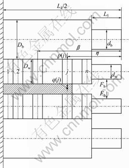
Fig.1 Schematic representation of roll system
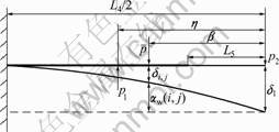
Fig.2 Beam model for work roll
unit opposite force; δi and δi,j are the deflections of origin and the ith point due to the unit force at the jth point, respectively. The model was employed to calculate the influence coefficients of both the backup roll and the work roll. The influence coefficient and the deflection expression of the work roll are described as Eqs.(1) and (2), respectively.

 (1)
(1)

 (2)
(2)
where stands for the deflection of the work roll at the ith element caused by unit force p1; E and μ are the elastic modulus and the Poisson ratio of the roll material, respectively; d and D are the work roll neck diameter and work roll barrel diameter, respectively; Yw(i) is the deformation of the ith element; ?xj is the width of the jth element;
  is the coefficient, =0 when j>m, otherwise, =1; Zw(i) is the flattening deformation of the work roll at the ith element due to q(j); Kw is the rigid displacement of the work roll axis. In his model, the difficulty is that when applying unit load p1 (unit rolling force or unit intermediate force between the rolls) at position η, unit opposite force p2 generated at the origin where the bending force was applied. In fact, the work roll chock is free in perpendicular direction, or the bending force has no effect on the deflection of the work roll. So, the generation of unit opposite force p2 is intricate, and no literature gave a rational explanation. Although the new formulas deduced in this study have the same effect as SHOHET’s, a rational illustration for SHOHET’s model is given as follows. When unit force p1 (supposing it is a unit rolling force) is applied, the generated force p2 can be seen as a virtual negative bending force that is in the direction of force p1, therefore, influence coefficient
  in Eq.(1) stands for the combination effect of p1 and p2. When p1 acts as an intermediate force between the rolls, p2 can be seen as the unit positive bending force. Considering the deformation of the work roll under rolling force and intermediate force, the effect of the negative and positive bending force will counteract with each other when the rolling force is equal to the intermediate force, if not, a extra deformation due to the unbalanced force (that is the bending force) will be included in deformation expression in Eq.(2), that is why the bending force just occurs in the static equilibrium equation [5].
Treating the deformation model of the work roll as a cantilever beam, as shown in Fig.3(a), explicit formulas of the influence coefficients can be obtained according to the theorem of Castigliano. Let η>β, then  =
=  . The bending and shear strain energy Ub1 and Us1, due to unit load p1 and virtual force p0, can be expressed as Eqs.(3) and (5), respectively.
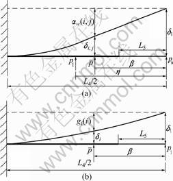
Fig.3 Cantilever beam model for work roll to calculate influence coefficient for unit rolling force (a) and unit bending force (b)

 (3)
(3)
Then,

 (4)
(4)
where I1 and I2 are moduli of section in roll neck and barrel, respectively.
 (5)
(5)
 (6)
(6)
where is the shear coefficient, which is taken as 4/3; G is the shear modulus; and A2 is the area of cross section of roll barrel. The deflection in the ith element due to unit load p1 and virtual load
  can be got in the similar method. The expressions are as follows:
 (7)
(7)
 (8)
(8)
The influence coefficient is denoted as Eq.(9) when β<η,
 (9)
(9)
The influence coefficient can also be attained by the same method when β>η.

 (10)
(10)
To calculate the influence coefficient for the work roll deflection due to the force generated by the roll bending mechanism, the diagrammatic sketch is shown in Fig.3(b). gf(i) is the influence coefficient for bending force, and the expression is shown as follows:

 (11)
(11)
Then, the deformation of the work roll at point i is described as

 (12)
(12)
Rolling force p(j) has an effect of decreasing the deflection of the work roll, instead, the rolling pressure q(j) between the rolls increases the deflection of the work roll.
3 Verification of formulations
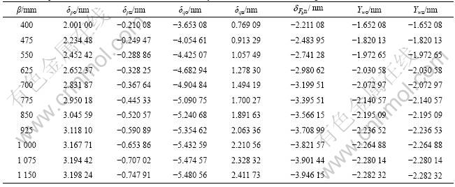
Considering the deflection of the work roll under a simple case that a unit rolling load p and a unit rolling pressure q between the rolls are acted on the work roll, the deformation of the work roll caused by p and q along roll barrel direction can be obtained, respectively. The elastic modulus and Poisson ratio of the work roll are 208.8 GPa and 0.3, respectively. Work roll neck length is 400 mm, and the diameters of the roll barrel and roll neck are 640 and 450 mm, respectively. The distance between the work roll bearings is 2 250 mm. The distance from unit force p to the bearing centre line is 700 mm, and that for unit force q is 550 mm. Substituting the known variables above to Eqs.(1), (2) and (9)-(12), respectively, the results can be got and shown in Table 1. Symbol δ stands for the deflection of the work roll and Y stands for the combination effect, subscripts p, q and Fb stand for the deflection caused by forces p, q and bending force, subscripts o and n stand for the old formulas (SHOHET’s formulas) and the new formulas. From Table 1, it can be found that the results computed from the two methods are different due to p and q and the sign is opposite from each other, but the combination effect of forces p and q is equivalent. Considering the effect of the bending force, let q be equal to 2 N, p be equal to 1 N, then a virtual unit positive bending force must be acted on the bearing centre line according to static equilibrium condition. So, three portions are included in the deformation of the work roll in light of the new method. The results are shown in Table 2, and the deformation of the work roll computed by the new formulas is equal to that by old formulas, which validates that the new method is right. To compare directly the two models, the flattening deformation is excluded. The sign is positive when the force increases the deflection of work roll; otherwise, it is negative, which can be seen from Tables 1 and 2.
According to the value computed by new formulas, the conclusion can be got that both rolling force and bending force have the effect of decreasing the
Table 1 Comparison of deflection distribution of work roll under two methods without bending force

Table 2 Comparison of deflection distribution of work roll by two methods with unit bending force
deformation of work roll, and then, the rolling pressure between the rolls has the opposite effect on four-high mill. So, if the contact length between rolls at the edge is diminished appropriately, it will decrease the deformation of the work roll and help to improve the quality of the strip.
Two numerical examples with and without the bending force were investigated to further evaluate the accuracy of the formulas. The deformation of rolls, the rolling pressure distribution and the outlet thickness of the strip got from the two methods were compared. Fig.4 shows the rolling pressure distribution for per unit width at the bending force of 0 and 1 MN. It shows that the results from the two formulas agree very well. The rolling pressure along the roll barrel increases with increasing bending force from 0 to 1 MN, especially at the edge contact region. The contact pressure beyond the strip width causes the extra deflection of the work roll. The same conclusion can be drawn from Eq.(12). The contact force still weakens the effect of the bending force. The deformation of the rolls is shown in Fig.5, and the same results are received from the two models. The maximum deformation of the work roll declines from 0.14 to 0.05 mm with increasing bending force from 0 to 1 MN, which illustrates that the bending force has a
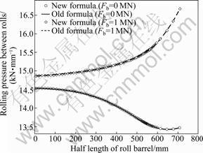
Fig.4 Comparison of rolling pressure distribution
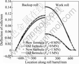
Fig.5 Comparison of deflection of rolls
strong ability to adjust the deformation of the work roll. The deformation of the backup roll just changes slightly. Fig.6 shows the outlet thickness of the strip calculated by using the two models, which also gives the same distribution for the two formulas. From Figs.4-6, the conclusion can be got that the formulas shown in Eqs.(9)-(12) can substitute formulas Eq.(1) and Eq.(2).

Fig.6 Comparison of thickness distribution of rolled strip
4 Conclusions
(1) The combination effect of the rolling force and bending force on work roll deflection is included in SHOHET’s influence coefficients. So, the contribution of the rolling force and rolling pressure between rolls to the deflection of work rolls is not very clear.
(2) New influence coefficients based on a cantilever beam model are deduced. The explicit expressions of influence coefficients caused by rolling force and bending force are given.
(3) The correctness of the formulas is validated by two numerical samples. The rolling pressure between rolls, deflection of the rolls and the thickness distribution of the rolled strip getting from the old and new formulas are same, which demonstrates that the new formulas are equivalent to SHOHET’s influence coefficients.
References
[1] GINZBURG V B. Steel-rolling technology: Theory and practice [M]. New York: Marcel Dekker Inc, 1989: 526-538.
[2] STONE M D, GRAY R. Theory and practice aspects in crown control [J]. Iron Steel Eng, 1965, 42(8): 73-83.
[3] SHOHET K N, TOWNSEND N A. Roll bending methods of crown control in four-high plate mills [J]. Journal of the Iron and Steel Inst, 1968, 206(11): 1088-1098.
[4] EDWARDS W J, SPOONER P D. Analysis of strip shape [C]// BRYANT G F. Automation of Tandem Mills. London: Iron and Steel Institute, 1973: 176-212.
[5] WANG Guo-dong. The shape control and theory [M]. Beijing: Metallurgical Industry Press, 1986: 307-313. (in Chinese)
[6] ZHANG Guo-min, XIAO Hong, WANG Chun-hua. Three- dimensional model for strip hot rolling [J]. Journal of Iron and Steel Research, International, 2006, 13(1): 23-26.
[7] GUO Remn-min. Prediction of strip profile in rolling process using influence coefficients and Boussinesq’s equations [J]. Journal of Manufacturing Science and Engineering, 1997, 119(2): 220-226.
[8] YUN K H, SHIN T J, HWANG S M. A finite element-based on-line model for the prediction of deformed roll profile in flat rolling [J]. ISIJ International, 2007, 47(9): 1300-1308.
[9] SALINMI M, FOROUZAN M R. Determination of bending actuators set points to control crown and flatness in hot rolling of strip [J]. Journal of Materials Processing Technology, 2002, 125/126(9): 670-677.
[10] YAO Lin-long. Three-dimensional analysis of strip rolling in a large production mill [J]. Journal of University of Science and Technology Beijing, 2003, 25(1): 57-61. (in Chinese)
[11] KIM T H, LEE W H, HWANG S M. An integrated FE process model for the prediction of strip profile in flat rolling [J]. ISIJ International, 2003, 43(12): 1947-1956.
[12] LIU Xue-feng, WANG Ling-yun. Analysis of elastic deformation of rolls system in rolling mill based on influential function and prediction of plate shape [J]. Journal of Chongqing University, 2000, 23(6): 87-90. (in Chinese)
[13] JIANG Z Y, ZHU H T, WEI D B, TIEU A K. An approach to analyse the special rolling of thin strip [J]. Journal of Materials Processing Technology, 2006, 177(1/3): 130-133.
[14] JIANG Z Y, ZHU H T, TIEU A K. Study of work roll edge contact in asymmetrical rolling by modified influence function method [J]. Journal of Materials Processing Technology, 2005, 162/163: 512- 518.
[15] JIANG Z Y, WEI D, TIEU A K. Analysis of cold rolling of ultra thin strip [J]. Journal of Materials Processing Technology, 2009, 209(9): 4584-4589.
(Edited by LIU Hua-sen)
Foundation item: Project(20050216007) supported by the Specialized Research Fund for the Doctoral Program of Higher Education of China
Received date: 2009-11-03; Accepted date: 2010-03-29
Corresponding author: ZHAO Tie-yong, Doctoral candidate; Tel: +86-335-8074462; E-mail: tieyongzhao2009@yahoo.com.cn

