
Electro-spark epitaxial deposition of NiCoCrAlYTa alloy on directionally solidified nickel-based superalloy
WANG Mao-cai(王茂才)1, WANG Wei-fu(王维夫)1, 2, XIE Yu-jiang(谢玉江)1, ZHANG Jie(张 杰)1
1. State Key Laboratory for Corrosion and Protection, Institute of Metal Research,
Chinese Academy of Sciences, Shenyang 110016, China;
2. School of Science, Northeastern University, Shenyang 110004, China
Received 16 April 2009; accepted 18 August 2009
Abstract: An 8 mm-high NiCoCrAlYTa coating was epitaxially built-up on a directionally solidified (DS) Ni-based superalloy blade tip by electro-spark deposition. Epitaxial morphologies of the coating and its microstructural characteristics were investigated by means of SEM, XRD and TEM etc. It is observed that the fine column-like dendrites originated from the γ′-particles or γ′-clusters of the DS substrate and are un-continuously coarsened. The β-phase particles precipitate and grow eutectically with the γ-phase. The orientation of fine column dendrites depends on electro-spark deposition processing parameters and the microstructure can be characterized with superfine γ and β phases.
Key words: electro-spark deposition; epitaxial growth; MCrAlY alloy; Ni-base superalloy
1 Introduction
Directionally solidified (DS) superalloys are more and more widely used as components of the gas turbine, e.g. the blade and vane, for their excellent fatigue strength. In DS superalloys, no transversal grain boundary exists. As a result, the DS blade possesses higher resistance to cracking along the direction perpendicular to the main stress[1] in comparison with the conventional casting blade with polycrystallines. To match the DS blade, epitaxially directional growth of clad coating on the blade tip along the growth direction has been expected for both preparing the oxidation-resistant coating and repairing the worn-blade tip[2].
MCrAlY alloys (M: Ni, Co, Fe), as well known, are the so-called the third generation advanced coating materials to protect nickel-based superalloy components against both oxidation and hot corrosion[3]. In the recent years, epitaxial growth of the MCrAlY alloy on DS superalloy substrate has been widely studied by using methods such as laser cladding [2, 4-5] and electro-spark deposition (ESD)[6-7]. The researches above show that NiCoCrAlY alloys possess the potential ability to grow epitaxially. NiCoCrAlYTa alloy is a developed MCrAlY alloy which has not only higher resistance to high temperature gas attack but also higher epitaxial growth performance due to the fact that the elements Ta and Co play a role in strengthening the matrix γ phase and the higher Al content (up to 8%, mass fraction) promotes β-phase formation. As a result, eutectic parallelly- growing of γ and β will be possible under a single- direction thermal flow gradient.
Electro-spark deposition[8], which is also called the electro-spark alloying (ESA)[9], is a micro-arc welding process in its nature. The deposition layer produced by every pulse electro-arc is usually very thin (in micrometer scale)[10]. Therefore, large temperature gradient and rapid cooling rate can be expected for each thin deposition. Nowadays, ESD processing units made by the authors have higher output power (up to 5 000 W) and higher pulse discharge frequency (up to 4 000 Hz). Previous works have shown that high-quality epitaxial MCrAlY coating can be produced by these ESD processing units on a Ni-based superalloy[6-7]. For the purpose of developing rebuilding process of the DS blade tip, a 8 mm-high NiCoCrAlYTa DS deposit coating was built-up on a real blade tip (DZ22 alloy), and the growth mechanism and influence factors were studied.
2 Experimental
The NiCoCrAlYTa alloy powder was prepared by argon-atomizing process with a chemical composition of (in mass fraction) Co 25%, Cr 20%, Al 8%, Y 0.6%, Ta 4% and balance Ni. The alloy powder was then used to make the electrode for ESD with the help of laser near-shape forming in a copper model with water-cooling. The electrode was 4-6 mm in diameter and about 50 mm in length.
An electro-spark deposition system included a main processing unit, a hand-held gun and the co-axis shield gas facility. A Ni-based DS superalloy, DZ22, was selected as the substrate for ESD. The ESD processing parameters were: power of 1 500 W, frequency of 300 Hz, and electrode rotating speed of 3 000 r/min. During ESD processing, the electrode moved on the blade tip continuously and the argon gas was used to shield the deposition zone with a flow rate of about 8 L/min.
The sample for micro structure observation was prepared by the following procedure: wire cutting→ grinding and polishing parallel to the growth direction→ etching the polishing surface with 5% H2SO4 solution. Optical microscopy, SEM, and XRD were used to investigate the morphologies and microstructures of the ESD coating. For TEM observation, the samples above continued to be thinned by emery paper grinding from two opposite surface till about 20 μm in thickness and then followed by chemically thinning in 25% HNO3 methanol solution until some tiny holes appeared. A Philips FEG-400 type scanning electron microscope was used for SEM observation and a TECNAI G220 type transmission electron microscope was used for identifying the microphases.
3 Results
3.1 General characteristics of built-up coating
Fig.1 shows the overview of the NiCoCrAlYTa ESD built-up coating on a DS blade tip. The built-up coating, which is free from apparent pore, fissure, cracks and other defects, is about 8 mm high, 2 mm wide and 15 mm long. Microhardness distribution along the growth direction (Fig.2) shows that the microhardness is uniform. The XRD result shown in Fig.3 indicates that the ESD coating is mainly composed of γ-phase (Ni-base solid solution) and β-phase (NiAl). Some block phases are observed to randomly distribute in the ESD coating (Fig.4). EDX analysis shows that the block phases should be a Y2O3・(AlCr)2O3, probably caused by high temperature oxidation during ESD processing.
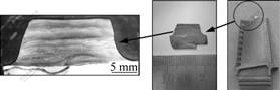
Fig.1 Overview of built-up layer on tip of DS DZ22 alloy blade
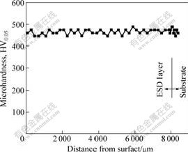
Fig.2 Microhardness distribution along growth direction of built-up layer
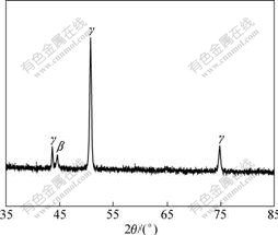
Fig.3 XRD pattern of built-up layer
3.2 Epitaxial growth characteristics of built-up coating
3.2.1 Initial epitaxial dendrite growth
As can be seen in Figs.5(a)-(c), the substrate of DZ22 alloy exhibits a directional solidification microstructure which is mainly composed of cubic-like prime γ′ phase existing in the dendrite and conglomeration-like prime γ′ phase existing in the interdendritic region.
Fig.6(a) exhibits a laminate-like and super-fine column-like microstructure of the built-up coating adjacent to the substrate. In the first thin deposited layer next to the substrate (about 10 μm thick), the superfine and vertical columns perpendicular to the interface can
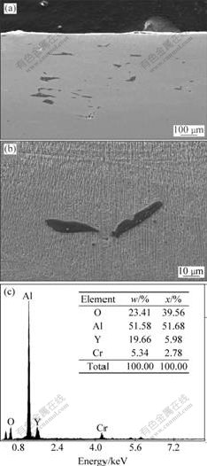
Fig.4 Morphology and distribution of black block-like phase (a), and its magnified image (b) and EDX analysis result (c)
be observed. Further observations (in high magnification) display that there are two typical interfacial morphologies between the ESD coating and the substrate, i.e. the fine column grows on the dendrite parts of the substrate and the fine column grows on the interdendritic parts of the substrate. The former seems to siphon the nano γ′ particle, resulting in climbing of the nano-γ′ particles along the column (see Fig.6(b)); whereas the later seems to grow up in an absorbing way to suck at the γ′ cluster (see Fig.6(c)). As a result, the initial end of the column is separated from the nano γ′ particle for the former or connected with the gathered γ′ cluster for the latter.
3.2.2 Precipitation of second phase at early growth stage
As shown in Fig.6(a) and Fig.7 (the magnification of Fig.6(a)), many observable white particles exist in the interval of two different columnar dendrites and display an eutectic-growth characteristics. These white particles seem to nucleate and precipitate from the fine columnar dendrite. The reason why the precipitate phase does not grow parallel to the fine column continuously should stem from the super-high cooling rate of ESD. During ESD process, the higher the cooling rate is, the more difficult the phase precipitation and growth are. Another fact that precipitation particles get more and more obviously outwards from the initial thin deposited layer to the following layers is also the evidence of the influence of cooling rate.
On the basis of the XRD result shown in Fig.3, the column dendrite should be γ phase and the precipitate should be β phase. The coexistence of γ phase and β phase shows that the β phase has a strong potential to eutectically grow with the γ phase. In addition, it can be
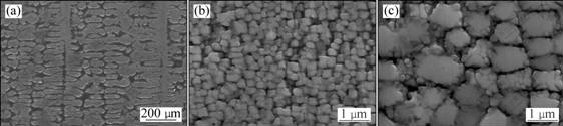
Fig.5 Microstructure of DZ22 DS alloy: (a) Low magnification; (b) γ′ phase in dendrite; (c) γ′ phase in interdendritic region
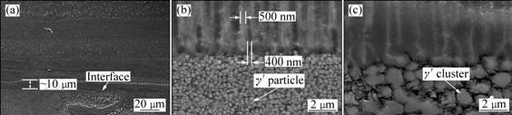
Fig.6 Microstructures of built-up layer: (a) Laminate microstructure with super-fine column dendrite; (b) Epitaxial growth of fine column to contact nano γ′ particle; (c) Epitaxial growth of fine column to contact γ′ cluster
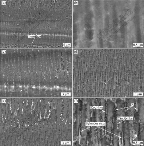
Fig.7 Precipitation morphologies of second phase: (a) Precipitates appearance in several thin deposited layers near to substrate; (b) Few precipitates in first thin deposited layer; (c) Precipitates in second thin deposited layer; (d) Precipitates in third thin deposited layer; (e) Precipitates in forth thin deposited layer; (f) Distinguished precipitates in fifth thin deposited layer
seen that the precipitates in front of the cellular columns make the columns growth stop (as marked “S” in Fig.7(f)). The coarse precipitate can also lead to the growth direction changes from their original orientation (as marked “C” in Fig.7(f)).
3.2.3 Dendrite epitaxial growth characteristics of built-up coating
In order to study the epitaxial growth characteristics of the built-up coating, the observations on microstructure changes were performed along those microhardness indentations. These indentations are in a line arrangement and perpendicular to the coating/ substrate interface (Fig.8), which implied that the horizontal line of each indentation is parallel to the interface and the vertical line of indentations is perpendicular to the interface (i.e. parallel to the expected epitaxial direction). Therefore, these microhardness indentations can be selected as the marks to identify the growth direction variety of the DS ESD coating. For convenience, these indentations were marked with numbers since they have equal interval (50 μm) in the ESD coating. Some of these indentations were selected and shown in Fig.9. The indentation at the interface, which is shown in Fig.9(a), was marked as “1”.
As mentioned above, one of these cross lines is parallel to the interface and the other one is vertical to the interface. Here, it is visible that the straight superfine column-like dendrites form vertically. The same situation can also be seen in the last thin deposited layer at the surface (Fig.9(b)). Along the indentation “1” up, the
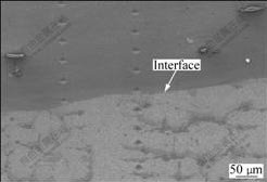
Fig.8 Microhardness indentations perpendicular to coating/substrate interface
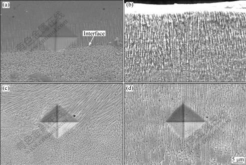
Fig.9 Overviews of dendrite morphology evolution along microhardness indentations from interface to ESD coating (indentations marked subsequently from interface to surface): (a) Interface (Indentation 1); (b) Surface; (c) Indentation 3; (d) Indentation 7
indentation “3”, which is about 100 μm from indentation “1”, locates at the zone where several groups of cellular dendrites exist with different growth orientations (Fig.9(c)), while a cellular-column dendrite morphology similar to indentation “1” appears again at the indentation “7” (Fig.9(d)). The results above imply that directional epitaxial growth morphology of the built-up coating mainly depends on the ESD process and is affected by the preferred crystal orientation of the DS DZ22 alloy substrate only in the initial deposited layers near the substrate. For ESD of NiCoCrAlYTa alloy, thermal gradient direction (heat flow direction) plays a decisive role in dendrite growth orientation.
In fact, the ESD built-up coating of about 8 mm in height is a multi-layered structure consisting of many thin deposited layers of micrometer scale. As can be seen from Fig.10, the interaction zone displays a mixed dendrite microstructure, which may stem from the second heat action of the subsequent thin deposited layer. In the interfacial zone, cellular-dendrite of the sublayer below is cut off and the new cellular-dendrite of the sublayer above begins to growth (Fig.10(a)), or the cellular-column dendrite of the sublayer above develops following the cellular-column track of the sublayer below (Fig.10(b)). In fact, microstructure of the interaction zones is variform corresponding to the parameters of the electro-spark deposition process. During manual ESD processing, the distance of the electrode to work-piece surface and the force on the electrode are difficult to be keep constant as well as the relevant electric parameters.
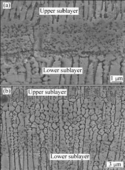
Fig.10 Micrographs showing two different morphologies of interaction zone: (a) Un-continuous transition zone; (b) Continuous transition zone
Besides, it can be obviously observed that the super-fine cellular columnar dendrite can crossover barriers (such as voids and second particles) on its growth path to grow without interruption, as shown in Fig.11 and Fig.4, which implies again that there is a
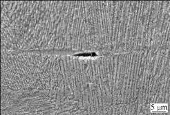
Fig.11 Micrograph showing un-continuous growth of fine columnar dendrite without change in direction through void
strong tendency of directional growth for the formation process of the superfine cellular-column dendrite.
3.2.4 TEM observations
Figs.12(a)-(f) show the TEM images of the ESD coating. In Fig.12(a), four parallel strips of bamboo-like structure, which consists of rod-like particles with different lengths, can be observed. The intervals between
strips are about 800-1 200 nm corresponding more or less to the one between the super-fine columns as shown in Fig.7. The electro-beam diffraction pattern from the bamboo-like dendrite (Fig.12(b)) shows characteristics of a BCC crystalline, i.e. β phase for the NiCoCrAlYTa ESD coating.
Fig.12(c) and Fig.12(d) clearly exhibit the existence of the nano-particles between two bamboo-like dendrites. According to the diffraction pattern (Fig.12(e)), the nano-particles can be identified to be BCC structure, i.e. β-phase. Similarly, the matrix should be FCC structure, i.e. γ-phase depending on the diffraction pattern shown in Fig.12(f) (zone B in Fig.12(c)). Fig.12(d) exhibits that γ-phase has a homogeneous cell sub-structure of about 6 nm, and some bright-white particles distribute randomly in it. These bright-white particles may be γ′-phases.
4 Discussion
According to Fig.9(a) and Fig.9(b), the rapid cooling rate may be calculated following the formula
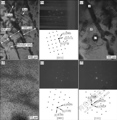
Fig.12 TEM images and selective zone diffraction patterns showing microstructures of sublayer near to interface between built-up coating and substrate: (a) Four parallel rows of bamboo-like dendrite; (b) Diffraction pattern from bamboo-like dendrite (marked A in Fig.(c)); (c) and (d) Magnified images showing nano-particles existing in inter-dendrites; (e) Diffraction pattern from nano-particles (marked C in Fig.(c)); (f) Diffraction pattern from matrix (marked B in Fig.(c))
below[11]:
 (1)
(1)
 (2)
(2)
where λ≈0.5 and 1.0 μm. Therefore the  is about 1×10⁶ K/s and 6×10⁵ K/s for the above two typical sub-layer correspondingly.
The result above indicates that the built-up coating has very high cooling rate ranging from 106 K/s to 105 K/s and has a different cooling rates from the first thin deposited layer (interface) to the last thin deposited layer (surface).
Temperature gradient G can be calculated according to the following consideration.
Assume that each thin deposited layer of the built-up coating is formed by a super rapid solidification of a micro-thin molten body produced during a single pulse deposition[12]. As shown in Fig.13, the micro-thin molten body, which is about 10-20 μm thick (according to Fig.6(a)), has a liquid/solid interface where the temperature[13] is
Tl=Ts≈Tm+ΔT=Tm-TmΓκ (3)
where Tl is liquid phase temperature at the interface, Ts solid one, Tm melting point for plane solidification, Γ Gibbs-Thomson number, and к curvature, being positive if cave is toward the liquid.
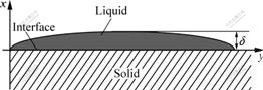
Fig.13 Schematic diagram showing spreading state of micro-thin molten body produced by single pulse electro-spark deposition on substrate
The Tm in Eq.(3) should be affected by interaction between the liquid phase and the solid phase, which results in a unstable solidification boundary when the molten body is sprayed on the solid surface. As a result, the transitive zone displays a different microstructural characteristics from the solid parts below (Fig.10). After that, the solidification boundary gets stable to rapidly go through the tiny molten body, resulting in a microstructure of cellular-column like or cellular-like dendrite.
If the molten body splashes down to the substrate to form a smooth thin deposited layer of 10-20 μm thick, then G≈105-106 K/cm, which is higher than that of laser rapid solidification (104-105 K/cm). In this case, super-fine column dendrite will form, no matter if the substrate is in DS structure. If the molten body drops down on the substrate to produce an non-uniform
deposit, then  where δ (thickness of
the non-uniform deposit) is higher than 10-20 μm. So, it is difficult to form a positive temperature gradient G in the deposit due to the thicker molten body. Of course, this is only an extreme condition. For manual ESD processing, the depositional styles are often varied. Therefore, the various growth dendrites along the built-up coating will be characterized.
As for the effect of the γ′-phase particle in DZ22 alloy on super-fine column-dendrite in the first thin deposited layer at the interface, the following two distinguish characteristics should be considered.
From Figs.6(b) and (c), both of the fine γ′-grain and coarse γ′-cluster act as the source to form the γ fine column with help of nuclear on a tiny volume of γ-γ′ solid eutectic[14] and keep a γ-γ′ conjugation relationship[14] during column-dendrite growth, which appears to be the so-called un-continuous coarsening[15]. An obvious difference between the γ′-grain and γ′-cluster is that γ′-cluster itself transforms to γ column dendrite and the γ′-particle climbs up the column. Thermal diffusion force stemming from the free energy gradient, ?μ, in material, obviously, is responsible because
f=-?μ (4)
For temperature gradient,
 (5)
(5)
 (6)
(6)
or
 (7)
(7)
where f represents thermal diffusion force, f ′ heat flow driving force, G temperature gradient, C solute concentration, Q immigrating thermal, m slope ration of a curve, k Bolzma constant and T absolute temperature.
According to the calculation of G above on the basis of the thickness of the initial thin deposited layer as shown in Fig.6(a), the G is 105-106 K/cm. This high temperature gradient will induce a force f enough to cause a thermal-diffusion-transform of the γ′-cluster to γ and/or a force f′ to cause climb-up of the γ′ particle along the columnar dendrite.
5 Conclusions
1) About 8 mm-high built-up coating of NiCoCrAlYTa alloy can be deposited on a DS DZ22 Ni-based superalloy blade tip by electro-spark epitaxial growth process.
2) The built-up coating is characterized by such features as multi-sublayered construction with transition zone and zones with microstructure of super-fine columnar dendrites and cellular dendrites. The growth direction of the dendrite is affected by ESD processing parameters. The layer consists of γ-dendrites and β-precipitate particles; and the precipitation and growth of the β-phase are along the γ-dendrite.
3) In the initial thin deposited layers, the fine columnar dendrites originate from the γ′-particle or γ′-cluster of the DS DZ22 alloy substrate and get un-continuous coarsening. The high temperature gradient stemming from the ESD process produces a driving force high enough to induce the migration of the γ′-particle and γ′-cluster.
References
[1] HUANG Qian-yao, LI Han-kang. High temperature alloy [M]. Beijing: Metallurgical Industry Press, 2002. 213. (in Chinese)
[2] BEZEN?ON C, SCHNELL A, KURZ W. Epitaxial deposition of MCrAlY coatings on a Ni-base superalloy by laser cladding [J]. Scripta Materialia, 2003, 49(7): 705-709.
[3] SCHNELL A, BEZEN C, KONTES M, KURZ W. Method of growing a MCrAlY-coating and particle coated with MCrAlY-coating. Us Patent No.0244676 [P]. 2004.
[4] FERREIRA P N, VILAR R, PINA J P, SILVA R C, SEQUEIRA A D. Structure of MCrAlY laser cladding coatings deposited on the single crystal alloy turbine blade [C]//Powder Materials: Current Research and Industrial Practices: III. Chicago: TMS, 2003: 247-258.
[5] BEZENCON C, H?BEL M, WAGNI?RE J D, KURZ W. Single crystal laser cladding of superalloy [C]//Surface engineering: In Materials Science II. San Diego: TMS, 2003: 133-140.
[6] XIE Y J, WANG M C. Epitaxial MCrAlY coating on a Ni-base superalloy produced by electrospark deposition [J]. Surface and Coatings Technology, 2006, 201(6): 3564-3570.
[7] XIE Y J, WANG M C, HUANG D W. Comparative study of microstructural characteristic of electrospark and Nd:YAG laser epitaxially growing coatings [J]. Applied Surface Science, 2007, 253(14): 6149-6156.
[8] JOHNSON R N. Electrospark deposition: Principle and application [C]//Society of Vacuum Coaters 45th Annual Technical Conference, Lake Buena Vista, 2002: 87-92.
[9] LAWRENCE E B, STEPHEN N H, MARK C N. Method and application for electrospark alloying, US Patent No.6417477 [P]. 2002.
[10] LIU J, WANG R J, QIAN Y Y. The formation of a single-pulse electrospark deposition spot [J]. Surface and Coatings Technology, 2005, 200(7): 2433-2437.
[11] CAI Ying-wen, FAN Xin-hui, LI Jian-guo, FU Heng-zhi. Effect of clusters on crystal growth from the melt [J]. Journal of Northwestern Polytechnical University, 1996, 14(2): 323-324. (in Chinese)
[12] XIE Y J, WANG M C. Microstructural morphology of electrospark deposition layer of a high gamma prime superalloy [J]. Surface and Coatings Technology, 2006, 201(3/4): 691-698.
[13] CHENG Guang, FU Heng-zhi. Non-equilibrium solidification new-type metallic materials [M]. Beijing: Science Press, 2005: 145. (in Chinese)
[14] PORTER A, RALPH B. The recrystallization of nickel-base superalloys [J]. Journal of Materials Science, 1981, 16(3): 707-713.
[15] MCKELLEN M. Directional solidification of high-temperature materials [M]. CHEN Shi-qin, CHEN Rong-zhang. Beijing: Aviation Industry Press, 1988: 321. (in Chinese)
(Edited by YANG Bing)
Foundation item: Projects(50671116, 50901081) supported by the National Natural Science Foundation of China
Corresponding author: WANG Mao-cai; Tel: +86-24-23915863; E-mail: wmc@imr.ac.cn
DOI: 10.1016/S1003-6326(09)60216-8

