纳米氧化铝作为第三层对热障涂层中热生长氧化物层的改善
来源期刊:中国有色金属学报(英文版)2013年第5期
论文作者:Mohammadreza DAROONPARVAR Muhamad Azizi Mat YAJID Noordin Mohd YUSOF Saeed FARAHANY Mohammad Sakhawat HUSSAIN Hamid Reza BAKHSHESHI-RAD Z. VALEFI Ahmad ABDOLAHI
文章页码:1322 - 1333
关键词:高温氧化;纳米热障涂层;热生长氧化物;尖晶石
Key words:high temperature oxidation; nano thermal barrier coatings; TGO layer; spinels
摘 要:在热障涂层的顶层与连接层界面之间会生成热生长氧化物层。当涂层热暴露在空气中时,这种热生长氧化物的生长会导致陶瓷层与连接层的剥落。研究了4种大气等离子喷涂热障涂层在空气中的耐高温氧化性能。将这4种涂层放在1000 °C的电炉中在空气下分别保温24、48和120 h。组织观察表明,在纳米NiCrAlY/YSZ/纳米Al2O3涂层中,热生长氧化物层的生长速率远比其它3种涂层中的低。EDS和XRD分析表明,在热生长氧化物(Al2O3)涂层上,生成了Ni(Cr,Al)2O4混合氧化物(尖晶石型)和NiO,在纳米NiCrAlY/YSZ/纳米Al2O3涂层中,这种生长在Al2O3层上的有害混合氧化物层的厚度比在其它涂层中的低很多。
Abstract: A thermally grown oxide (TGO) layer is formed at the interface of bond coat/top coat. The TGO growth during thermal exposure in air plays an important role in the spallation of the ceramic layer from the bond coat. High temperature oxidation resistance of four types of atmospheric plasma sprayed TBCs was investigated. These coatings were oxidized at 1000 °C for 24, 48 and 120 h in a normal electric furnace under air atmosphere. Microstructural characterization showed that the growth of the TGO layer in nano NiCrAlY/YSZ/nano Al2O3 coating is much lower than in other coatings. Moreover, EDS and XRD analyses revealed the formation of Ni(Cr,Al)2O4 mixed oxides (as spinel) and NiO onto the Al2O3 (TGO) layer. The formation of detrimental mixed oxides (spinels) on the Al2O3 (TGO) layer of nano NiCrAlY/YSZ/nano Al2O3 coating is much lower compared to that of other coatings after 120 h of high temperature oxidation at 1000 °C.
Trans. Nonferrous Met. Soc. China 23(2013) 1322-1333
Mohammadreza DAROONPARVAR1, Muhamad Azizi Mat YAJID1, Noordin Mohd YUSOF1, Saeed FARAHANY1, Mohammad Sakhawat HUSSAIN1, Hamid Reza BAKHSHESHI-RAD1, Z. VALEFI2, Ahmad ABDOLAHI1
1. Department of Materials, Manufacturing and Industrial Engineering, Faculty of Mechanical Engineering, Universiti Teknologi Malaysia, 81310, Johor Bahru, Johor, Malaysia;
2. School of Metallurgy and Materials, College of Engineering, University of Tehran, P. O. Box 11155-4563, Tehran, Iran
Received 27 July 2012; accepted 10 December 2012
Abstract: A thermally grown oxide (TGO) layer is formed at the interface of bond coat/top coat. The TGO growth during thermal exposure in air plays an important role in the spallation of the ceramic layer from the bond coat. High temperature oxidation resistance of four types of atmospheric plasma sprayed TBCs was investigated. These coatings were oxidized at 1000 °C for 24, 48 and 120 h in a normal electric furnace under air atmosphere. Microstructural characterization showed that the growth of the TGO layer in nano NiCrAlY/YSZ/nano Al2O3 coating is much lower than in other coatings. Moreover, EDS and XRD analyses revealed the formation of Ni(Cr,Al)2O4 mixed oxides (as spinel) and NiO onto the Al2O3 (TGO) layer. The formation of detrimental mixed oxides (spinels) on the Al2O3 (TGO) layer of nano NiCrAlY/YSZ/nano Al2O3 coating is much lower compared to that of other coatings after 120 h of high temperature oxidation at 1000 °C.
Key words: high temperature oxidation; nano thermal barrier coatings; TGO layer; spinels
1 Introduction
Turbine blades are generally protected by thermal barrier coatings (TBCs) at high temperatures [1,2]. A normal TBC system consists of a ceramic top coat and a metallic bond coat (MCrAlY) onto the nickel-based superalloy as a substrate. MCrAlY (M=Ni, Co or mixture of these two) layer can provide a good thermal expansion match and adhesion between the ceramic top coat and the substrate as well as protect the substrate from further oxidation and hot corrosion [3].
The transfer of oxygen through the top coat towards the bond coat can occur at elevated temperatures by micro-cracks and interconnected pinholes inside the top coat. Therefore, an oxidized scale can be formed on the bond coat which is termed thermally grown oxide (TGO) layer which is related to the oxidation of the bond coat. The TGO layer plays an important role in the failure of TBC due to the growth of the TGO layer during oxidation [2,3].
The TGO thickness can increase during oxidation process which is accompanied by evolution of stress at the interface of bond coat/YSZ (yttria stabilized zirconia). This stress causes the delamination of coating at the interface of bond coat/YSZ [1,4]. It has been reported that the stresses in TBC increase with a growing TGO layer [5]. Hence, the thicker TGO layer has larger stress than the thinner one [3,5]. It has been reported that Ni(Cr,Al)2O4 (as spinel) and NiO were formed at the Al2O3 layer/ceramic coating (YSZ) interface in TBC systems with MCrAlY bond coat, during thermal exposure at temperature high than 1000 °C [5,6]. These two oxides were found to be preferred nucleation sites for crack initiation, leading to premature top coat separation from the bond coat. Therefore, the mixed oxides have negative effect on the durability of TBC systems because of the rapid local volume increase [5] that generates stresses. The previous investigations reported that the maximum radial stress of bi-layered TGO (Al2O3/detrimental mixed oxides) is about five times and the difference of maximum axial stress is about 10 times larger than those of the mono-layered TGO (Al2O3). It indicates that the bi-layered TGO has larger stresses in comparison with the mono-layered TGO [2,3].
(Cr,Al)2O3, Ni(Cr,Al)2O4 (spinel(CS)) and NiO are termed as (Cr,Al)2O3・Ni(Cr,Al)2O4・NiO, or abbreviated as CSN (detrimental mixed oxides). CHEN et al [6] reported that the formation of CSN is a result of compositional inhomogeneity in the air-plasma sprayed TBC system during thermal exposure in air. It has been noted that it is impossible to completely eliminate Ni(Cr,Al)2O4 and NiO from the TGO (Al2O3) layer [3,5,6].
It was found that a continuous Al2O3 layer could develop at the ceramic/bond coat interface in air plasma-sprayed TBC systems under a low oxygen pressure condition (with a minimum of oxygen activity) [3]. This continuous and thin Al2O3 (TGO) layer can act as a diffusion barrier to suppress the formation of CSN during later thermal exposure in service [6]. Therefore, more research is required to find other techniques for creation of a dense, continuous and thin Al2O3 layer onto the bond coat (NiCrAlY) during oxidation.
The presence of a dense Al2O3 layer over the YSZ coating reduces the oxygen permeation towards the bond coat and improves the lifetime of TBCs during oxidation [7,8]. Also, the existence of fine alumina particles as a dense layer over the YSZ coating reduces the partial pressure of oxygen at the bond coat/YSZ interface and considerably decreases the TGO growth during oxidation. There are two mechanisms for transferring oxygen through the YSZ layer towards the bond coat at elevated temperatures [1], i.e., ionic diffusion mechanism through the crystalline structure of ZrO2 and gas penetration mechanism through porosities and micro-cracks. But, the permeation of oxygen through the YSZ layer by gas infiltration mechanism is much more than the infiltration of oxygen by ionic diffusion mechanism at elevated temperatures. In addition, the oxygen diffusivity from the crystalline structure of Al2O3 is much lower in comparison with that of ZrO2 [1,8].
The nanostructured bond coat shows a better oxidation behavior in comparison with the micro- structured bond coat at elevated temperatures [9-11]. The main advantage of the nanostructured NiCrAlY coatings is the acceleration of the formation of a protective α-Al2O3 (TGO) layer that can prevent the further oxidation of the NiCrAlY layer [10-12]. Most of the previous researches noted that the major failure mechanisms of TBCs are mainly related to the growth of TGO layer [13,14] and the formation of CSNs on the Al2O3 (TGO) [3,5-6].
It is worth to mention that there is a major problem during the production of nanostructured ceramic coatings from the nano ceramic powders. This problem is feeding of the nano-powders into the plasma. The nano-powders adhere to the walls of feeding system and it becomes extremely difficult to move them towards the plasma torch due to their high specific area and low mass [15].
The majority of previous studies described the failure mechanism of TBCs due to TGO growth and especially internal oxidation of the bond coat during oxidation. Therefore, the main purpose of this research is to obtain a novel coating (nano NiCrAlY/YSZ/nano Al2O3 as an outer layer), to reduce the growth of the TGO layer and to diminish the formation and growth of detrimental mixed oxides onto the Al2O3 (TGO) layer during high temperature oxidation.
2 Experimental
2.1 As-received materials
Nickel based superalloy (Inconel 738) squares with dimensions of 25 mm×25 mm×6 mm, which were grit blasted with alumina particles, were used as substrates. Four types of commercial powders were selected: Amdry 962 (Ni-22Cr-10Al-1Y, 52-106 μm in size) as bond coat, Metco 204 NS-G (ZrO2-8%Y2O3, 11-106 μm in size), Amdry 6062 (normal α-Al2O3 with high purity, 15-80 μm in size) and Inframat LLC 0802 ( nano α-Al2O3 with high purity, 80 nm in size) as TBC (refractory ceramics).
2.2 Granulation of nano Al2O3 powders
In order to overcome the problem related to using nanoparticles described in introduction section, reconstitution of the nano particles into micrometer sized granules is very essential. Hence, the nano Al2O3 powders with average particle size of nominally less than 80 nm and poly vinyl alcohol (PVA) as a binder were used as starting materials. In this method, 50 g of PVA was dissolved in 80 mL of distilled water at 200 °C using a magnetic stirrer. At the same time, the nano Al2O3 particles were dispersed in distilled water using an ultrasonic machine for 30 min at 60 °C. Then, the dispersed nano-Al2O3 solution was added to PVA solution using a magnetic stirrer at 250 °C for 45 min. The water in the solution was removed using a rotary-evaporator.
These granulated powders were dried using a normal furnace at 200 °C for 145 min. Hence, these agglomerated powders were sieved through 150 μm, 100 μm and finally through 50 μm meshes in order to obtain adequate shape and size suitable for thermal spraying. Finally, the size distribution of the granulated nano Al2O3 powders (spray-able powders) used for air plasma spray was between 80 and 100 μm. The most favorable size of these granules was in the range of 10-110 μm [15].
2.3 Synthesis of nanocrystalline NiCrAlY powders
The commercial NiCrAlY (Amdry 962) powders were milled by a planetary ball mill (Retsch PM 400, made in Germany) in order to obtain the nano-crystalline NiCrAlY powders as bond coat in a TBC system. This powder was milled at a rotation speed of 180 r/min for 36 h in an argon environment. The direction of movement of the sun wheel was opposite to that of the grinding jars in the ratio of 1:2. The stainless steel balls with diameter of 8 mm were used, and the mass ratio of the stainless steel mill balls to the powders was 10:1.
2.4 Production of TBCs
The atmospheric plasma spraying was carried out using a Sulzer-Metco 3MB (Westbury L.I.N.Y) plasma spray system. Four types of coatings were generated by atmospheric plasma spray (APS) method, which included: 1) normal NiCrAlY/YSZ, 2) nano NiCrAlY/YSZ, 3) normal NiCrAlY/YSZ/normal Al2O3 as an outer layer and 4) nano NiCrAlY/YSZ/nano Al2O3 as an outer layer coatings. Table 1 exhibits the thickness of the as-sprayed coatings. The parameters of atmospheric plasma spraying are shown in Table 2.
2.5 Isothermal high temperature oxidation test and microstructural characterization
The as-sprayed coatings were heated in a normal electric furnace under air atmosphere at 1000 °C for 24, 48 and 120 h and then cooled to ambient temperature inside the furnace (Fig. 1). The microstructural characterization of the coatings before and after oxidation was carried out using scanning electron microscopy (SEM, Philips XL-40), field emission scanning electron microscopy (FESEM, Hitachi S-4160) equipped with energy dispersive spectrometer (EDS). In order to determine the type of oxide phases on the bond coat, XRD was conducted (Siemens-D500) by using Cu Kα line generated at 40 kV and 35 mA.
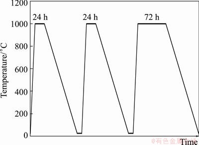
Fig. 1 Isothermal oxidation cycle of TBCs (heating and cooling in furnace media)
3 Results
3.1 Microstructural characterization of as-sprayed TBCs
Figure 2 shows the cross section of as-sprayed coatings. It can be seen that the YSZ and normal Al2O3 layers have formed a composite layer of YSZ/normal Al2O3 coating (Fig. 2(a)). On the other hand, YSZ and nano Al2O3 layers have formed a composite layer of YSZ/nano Al2O3 coating (Fig. 2(b)). The lamellar structure as one of the characteristics of plasma sprayed depositions was seen in all the coatings after atmospheric plasma spraying. This structure was also observed for normal NiCrAlY/YSZ and nano NiCrAlY/YSZ coatings, as shown in Figs. 2(c) and (d), respectively.
Table 1 Types of TBCs and thickness of layers
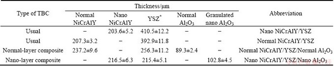
Table 2 Optimized parameters of air plasma spraying method
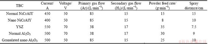

Fig. 2 SEM micrographs of cross section of as-sprayed TBCs
Fig. 3 FESEM images of surface of as-sprayed nanostructured Al2O3 (a) and NiCrAlY (b) layers
Figure 3 shows FESEM images of the surface of as-sprayed nanostructured Al2O3 and NiCrAlY layers. The average grain sizes of the as-sprayed nanostructured Al2O3 and NiCrAlY layers are estimated to be (92.8±12.4) and (55.1±15.7) nm, respectively.
Figure 4 demonstrates FESEM images of the surface of as-sprayed microstructured YSZ, Al2O3 and NiCrAlY layers in high magnification. The average grain sizes of the as-sprayed microstructured YSZ, Al2O3 and NiCrAlY layers are estimated to be (1.06±0.22), (0.45±0.09) and (0.58±0.16) μm, respectively.
The outer layer surfaces of the as-sprayed coatings are shown in Fig. 5. Some cracks and pinholes are observed on the surface of YSZ and normal Al2O3 layers. Whereas, the surface of nano Al2O3 layer shows the lower pinholes and micro-cracks in comparison with the normal Al2O3 and YSZ layers.
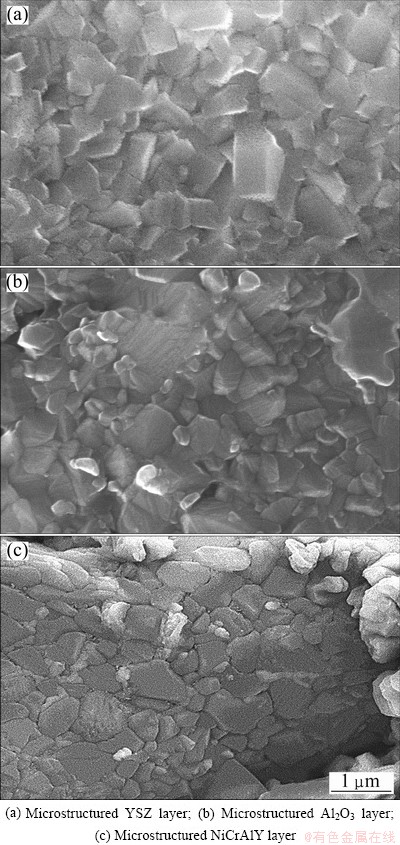
Fig. 4 FESEM images of surface of as-sprayed layers
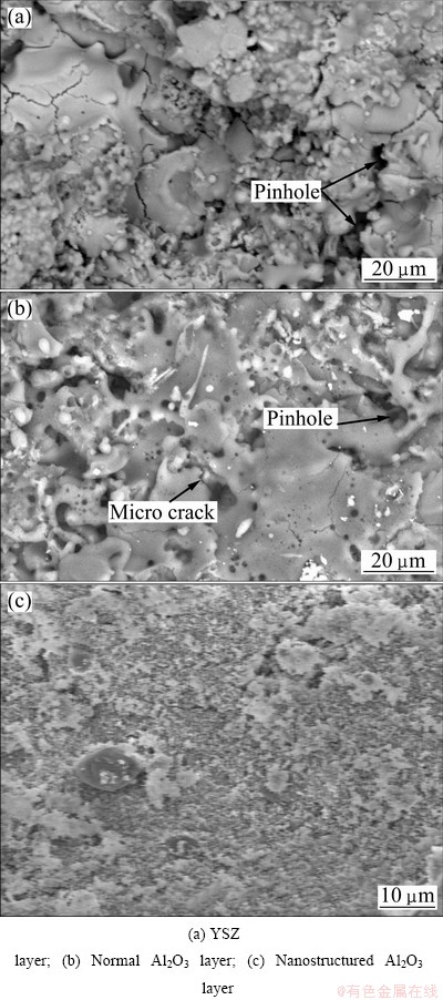
Fig. 5 Morphologies of surface of as-sprayed coatings
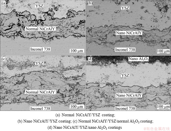
Fig. 6 SEM micrographs of cross section of coatings after oxidation at 1000 °C for 120 h
3.2 Microstructural characterization of TBCs after oxidation at 1000 °C
Figure 6 shows the cross section of coatings after oxidation at 1000 °C for 120 h. It can be seen that an oxide scale (TGO) has been formed at the bond coat/YSZ interface of all the coatings after oxidation, due to oxygen diffusion through the ceramic layer towards the bond coat. Moreover, the internal oxidation of the bond coat occurred during oxidation, due to oxygen infiltration through the porosities of the bond coat and micro-cracks of TGO layer into the bond coat during oxidation at elevated temperatures. It is worth to mention that the oxidized areas (dark regions) within the bond coat of nano NiCrAlY/YSZ/nano Al2O3 coating are less compared to that of other coatings.
Figure 7 exhibits the TGO layer of four types of TBCs in high magnification after oxidation at 1000 °C for 120 h. It can be seen that a dense and continuous TGO layer has been formed on the nanostructured NiCrAlY layer of nano NiCrAlY/YSZ and nano NiCrAlY/YSZ/nano Al2O3 coatings, as shown in Figs. 6(b), 7(b) and 6(d). However, TGO thickness in nano NiCrAlY/YSZ/nano Al2O3 coating is lower in comparison with that in the nano NiCrAlY/YSZ coating, because of the presence of nanostructured Al2O3 top layer over the YSZ coating. On the other hand, the TGO thickness in nano NiCrAlY/YSZ/nano Al2O3 coating is much lower than that in other coatings specially in normal NiCrAlY/YSZ coating (Fig. 7(a)).
The chemical composition of TGO (Al2O3) layer was detected by EDS analysis, which shows higher content of oxygen and aluminum and lower content of nickel and chromium (Fig. 8).
On the other hand, some protrusions are observed at the interface of TGO/YSZ as marked by arrows in Fig. 9(a). It was reported that the summit of these protrusions is an appropriate place for stress concentration [16] which leads to micro-crack formation and nucleation at TGO/YSZ interface (see Fig. 9(b)).

Fig. 7 TGO layer of TBCs after oxidation at 1000 °C for 120 h in high magnification

Fig. 8 EDS analysis of TGO layer after oxidation at 1000 °C for 48 h
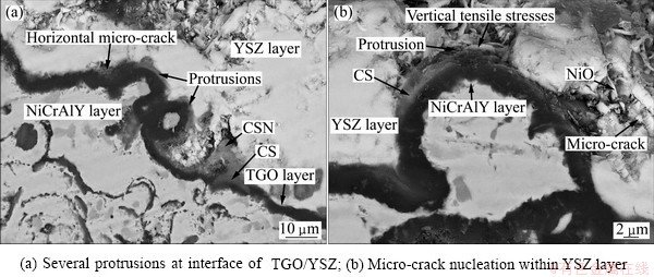
Fig. 9 FESEM images of TGO layer of normal TBCs after oxidation at 1000 °C for 120 h

Fig. 10 TGO thickness vs oxidation time at 1000 °C for four types of TBCs
The rate of TGO growth after isothermal oxidation at 1000 °C for 24, 48 and 120 h was determined by measuring the thickness of TGO layer. TGO thickness was measured on each cross-sectional SEM micrograph at more than 10 different locations and the average value was reported as TGO thickness. The variations of TGO thickness as a function of oxidation time are plotted in Fig. 10. As can be seen, the thickness of TGO layer increases with increasing oxidation time up to 120 h for all the samples. In addition, the rate of TGO growth in normal NiCrAlY/YSZ coating is higher than that in other coatings. The maximum growth rate of TGO layer belongs to normal NiCrAlY/YSZ coating and the minimum growth rate of TGO layer belongs to nano NiCrAlY/YSZ/nano Al2O3 coating after oxidation at 1000 °C for 120 h. The decrease in TGO thickness of nano NiCrAlY/YSZ/nano Al2O3 coating is about 62% in comparison with the normal NiCrAlY/YSZ coating.
According to Fig. 11, TGO layer consists of two layers: the outer layer (gray layer in point A) and the inner layer (darker layer in point B).
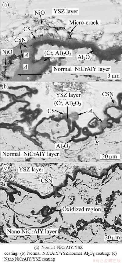
Fig. 11 FESEM images of bi-layered TGO in usual TBC after oxidation at 1000 °C for 120 h
The EDS analysis of bi-layered TGO showed large amounts of Ni, Cr, Al, and O in the outer layer of TGO (Figs. 12(a)-(e)), while a high concentration of Al and O was observed in the inner layer of TGO, as shown in Fig. 12(f). CHEN et al [6] found that the outer layer of TGO contained 15%-45% Ni, 8%-24% Cr and 2%- 30% Al (mole fraction). This chemical composition (Fig. 12(a)) identified a mixture (CSN) of chromia ((Cr,Al)2O3), spinel or CS (Ni(Cr,Al)2O4), and nickel oxide (NiO). These detrimental mixed oxides had been reported by other researchers [17,18]. Based on CHEN et al’s studies [5,6], NiO usually had a granular shape (Fig. 11(a)). This oxide was easily detected by EDS because of high concentration of Ni (Fig. 12(b)). When a Ni unit cell is transformed to NiO, an increase of -67% in volume can be expected at TGO/YSZ interface [19] and also NiO includes outward growth. So, this oxide can easily grow inside the ceramic coating and finally lead to TBC delamination during extended thermal exposure in air [20]. It is difficult to realize (Cr,Al)2O3 from Ni(Cr,Al)2O4 by EDS. But, CHEN et al [6] recognized that oxides containing <8% Ni (mole fraction) and >35% (Al+Cr) were (Cr,Al)2O3 (Fig. 12(c)), as NiAl2O4 contained 13%-16% Ni and 27%-30% Al (Fig. 12(d)). On the other hand, the oxides comprising 8%-16% Ni and >35% (Al+Cr) can be recognized as Ni(Cr,Al)2O4 (spinel) , as shown in Fig. 12(e).
Furthermore, the detrimental mixed oxides such as Ni(Cr,Al)2O4 (spinel(CS)), NiO, NiAl2O4 were detected in addition to Al2O3, γ/γ′ and β phases by X-ray diffraction analyses of oxide phases on the NiCrAlY layer after oxidation at 1000 °C for 120 h (Fig. 13) . It should be mentioned that the spinel was formed via solid phase reactions between Al2O3 (or Cr2O3) and NiO [17,18].
4 Discussion
According to Fig. 4, the nano Al2O3 layer has the lowest pinholes and micro-cracks in comparison with the normal Al2O3 and YSZ layers. In this condition, the nano Al2O3 layer can prevent the infiltration of oxygen into the YSZ layer, resulting in significantly reducing the TGO growth at the bond coat/YSZ interface, as shown in Fig. 6(d) and Fig. 7(d).
During the isothermal oxidation, the TGO layer was formed at the bond coat/YSZ interface for all the coatings due to high affinity of Al for reaction with O, as follows:
2Al+(3/2)O2→Al2O3 (1)
So, outward infiltration of Al and inward diffusion of O lead to the formation of Al2O3 on the bond coat. The EDS analysis of the TGO layer showed higher percentage of O and Al and lower percentage of Ni and Cr, as shown in Fig. 8. It means that TGO layer is mainly combined with Al2O3.

Fig. 12 EDS analyses of bi-layered TGO

Fig. 13 XRD pattern of oxide phases on NiCrAlY layer after 120 h of oxidation
Several protrusions were observed at the interface of TGO/YSZ after oxidation. The nucleation of micro-cracks and the spallation of the ceramic layer occur at the summit of protrusions which are appropriate place for stress concentration. TGO usually consists of large residual compressive stresses when the temperature of TGO layer decreases to environment temperature, because of its thermal expansion mismatch with substrate [8]. During the subsequent thermal exposure in air, the stress relieving occurs, which is accompanied with tensile stress parallel to TGO/ceramic layer interface that leads to the formation of cracks and separation at interface.
The above mentioned phenomenon in plasma sprayed TBCs during thermal exposure in air can be explained by the following steps:
1) The growth of the TGO layer can lead to the vertical tensile stresses at the interface of TGO/YSZ and within the YSZ layer (see Fig. 14(a)).
2) The progress of horizontal micro-cracks in the ceramic layer during thermal exposure is due to those stresses on the interface of TGO/YSZ layers, as shown in Fig. 14.
3) The spallation of the ceramic layer from the bond coat occurs when the length of lateral micro-cracks reaches to the length of critical crack. The horizontal micro-cracks cannot penetrate into the NiCrAlY layer at high temperatures because of their ductility. In addition, there are many cavities at the interface of NiCrAlY/YSZ which can resist the growth of micro-cracks into the NiCrAlY layer during oxidation [11].
Thinner TGO layer can be also seen in Figs. 7(d) and Fig. 10. The layer can predict an increase in the lifetime of TBCs at elevated temperatures. Moreover, finite-element analyses showed that the stresses in a TBC system increase with a growing TGO layer [5].
The rate of TGO growth is very fast during the first 24 h of oxidation, as shown by arrows in Fig. 10 (an instantaneous TGO growth). This case is due to the inward diffusion of oxygen and outward penetration of aluminium. Then, the Al2O3 layer is formed on the bond coat and the diffusion of oxygen towards the bond coat is decreased, so the rate of TGO growth becomes slow after 24 h. Furthermore, it should be mentioned that the growth of the TGO layer approximately follows a parabolic manner.
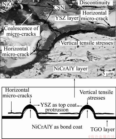
Fig. 14 Spallation of ceramic layer occuring at summit of protrusions and progress of horizontal micro-cracks in ceramic layer during thermal cyclings due to vertical tensile stresses onto interface of TGO/YSZ layers
It is worth to mention that in nano NiCrAlY/ YSZ/nano Al2O3 coating, when a continuous oxide layer (Al2O3 or mono-layered TGO) is formed at the ceramic/ bond coat interface, the oxygen partial pressure at the oxide/metal interface would be decreased to the formation pressure of Al2O3, which is the lowest value among the various species present, making Al2O3 the most favorable oxide product. Since Al2O3 is a stoichiometric oxide, the permeability of oxygen ions from Al2O3 particles is much less in comparison with that from ZrO2 particles [8]. As mentioned in introduction section, the diffusion of oxygen through the ceramic layer by gas penetration mechanism through porosities and micro-cracks is much more than the penetration of oxygen by ionic diffusion mechanism through crystalline structure of the ceramic layer at elevated temperatures. Therefore, the oxygen diffusivity from the crystalline structure of nano Al2O3 is much lower compared to that of ZrO2. Indeed, the better oxidation behavior of nano NiCrAlY/YSZ/nano Al2O3 coating is mainly attributed to: 1) the existence of a dense nanostructured ceramic layer with less interconnected pinholes and micro-cracks on the YSZ coating, and 2) utilizing the nanostructured NiCrAlY as bond coat in a nano TBC system, simultaneously (see Fig. 2(b)).
The formation of a uniform, dense and continuous Al2O3 (TGO) layer on the nanostructured bond coat is seen in Figs. 6(b) and (d). This behavior is due to the accelerated Al2O3 (TGO) growth during the initial exposure of the nanostructured bond coating at high temperatures. This accelerated growth may be attributed to the increased Al transport through the higher level of grain boundaries of the nanostructured bond coating at elevated temperatures [21] as observed in Fig. 10 for nano NiCrAlY/YSZ coating.
With regard to the presence of TGO layer at NiCrAlY/YSZ interface, the infiltration of oxygen into the bond coat can be explained by the following factors:
1) The existence of interconnected porosities which are related to the characteristics of plasma sprayed coatings;
2) The diffusion of oxygen through porosities of YSZ layer towards the TGO and NiCrAlY layers at elevated temperatures;
3) The formation of micro-cracks in TGO layer due to the TGO thickness increasing.
The above mentioned parameters can provide narrow pathways for infiltration of oxygen into the NiCrAlY layer at elevated temperatures. In this regard, nano Al2O3 as outer layer of YSZ/nano Al2O3 coating suppresses the penetration of oxygen into the YSZ layer during isothermal oxidation. It has been noted that normal Al2O3 top layer over the YSZ coating reduced the oxygen activity at NiCrAlY/YSZ interface [8].
With regard to the previous report [6] and the chemical compositions identified by EDS (Fig. 12) in this research, it can be inferred that the outer layer of TGO is mainly composed of NiO, (Cr,Al)2O3, and Ni(Al,Cr)2O4 (spinel or CS), and the inner layer of TGO is composed of Al2O3. The formation of these compounds during isothermal oxidation is also confirmed with XRD result.
The Al2O3, NiO, and Cr2O3 oxides can be simultaneously formed at the interface of NiCrAlY/YSZ during oxidation. However, due to the fact that Al2O3 is the most thermodynamically stable oxide, and only Al2O3 can continue to grow after a continuous TGO is developed. Moreover, the formation of NiO and Cr2O3 oxides is due to the depletion of Al at NiCrAlY/TGO interface and reaction of Ni, Cr with oxygen during oxidation (reactions (2) and (3)). Then, according to reactions (4) and (5), Ni(Al,Cr)2O4 spinels will be eventually formed on the TGO (Al2O3) layer, which are mainly attributed to the reaction of NiO with Al2O3 and Cr2O3. On the other hand, this NiAl2O4 (spinel) can be formed at Al2O3/YSZ interface during thermal exposure in air according to reactions (6) and (7). On the other hand, NiO can be created by reaction (8).
2Cr+(3/2)O2→Cr2O3 (2)
Ni+(1/2)O2→NiO (3)
NiO+Cr2O3+Al2O3→Ni(Al,Cr)2O4 (spinel) (4)
NiO+Al2O3→NiAl2O4(spinel) (5)
Ni+2Al+2O2→NiAl2O4 (6)
3Ni+4Al2O3→3NiAl2O4+2Al (7)
3Ni+NiAl2O4→4NiO+2Al (8)
It was suggested that Ni infiltrates through the micro-cracks across the Al2O3 scale (TGO) and can form Ni-rich regions at the interface of Al2O3/ceramic layer during oxidation [3,6]. Lower concentration of Al in the nickel-rich regions (oxides) leads to movement of Al from the Al2O3 area into the (Cr,Al)2O3 region and then eventually to the Ni(Cr,Al)2O4 /NiO area. Cr2O3 oxides are usually located in matrix of NiO oxide and then NiCr2O4 spinel will be formed by the following reaction [19]:
NiO+Cr2O3→NiCr2O4 (spinel) (9)
It can be said that the higher TGO growth rate promotes the onset of undesirable fast-growing non alumina oxides that form protrusions and accelerate the TBC failure mechanisms. In this work, the higher TGO growth rate in the normal TBC system can be mostly attributed to the spinels (CS) formed at the ceramic/bond coat interface since diffusion through chromia ((Cr,Al)2O3) is faster than through Al2O3 (TGO layer) [22-24]. The lower TGO growth rate in the nano TBC system can be mainly related to the slow diffusion through the Al2O3 (TGO) before the initially formed Al2O3 is completely transformed to chromia+spinel (CS), which prolongs the slow TGO growth, as marked by arrow in Fig. 10. This case is primarily due to the formation of a nearly continuous and thin TGO layer at the ceramic/bond coat interface of YSZ/nano Al2O3 coating during isothermal oxidation at elevated temperatures.
As mentioned, the growth of the TGO layer (particularly bi-layered TGO) can lead to the vertical tensile stresses at the interface of TGO/YSZ and within the YSZ layer. In this work, the creating of micro-cracks at the interface of TGO/YSZ can be mainly attributed to TGO growth which can impose excessive stresses to the zirconia layer during oxidation. It can be said that the nanostructured Al2O3 top layer over the YSZ coating can act as a strong barrier for oxygen infiltration by gas penetration mechanism and subsequently reduce TGO growth and oxidation of the bond coat with the aid of the nanostructured NiCrAlY layer.
The CSN as outer layer of TGO plays an important role in the premature failure of TBCs. The formation and growth of detrimental mixed oxides (specifically spinels) can be considerably suppressed using the nanostructured Al2O3 as outer layer of nano NiCrAlY/YSZ/nano Al2O3 coating. This case is attributed to the packness of nanostructure and the absence of micro-cracks and pinholes in the nanostructured Al2O3 layer [25]. Thus, detrimental oxides could not be extensively formed (Fig. 15) owing to the fact that they need more oxygen to be produced on the Al2O3 (TGO) layer. It can be deduced that the lower TGO thickness and minimum of CSN formation in nano NiCrAlY/YSZ/nano Al2O3 coating are responsible for the better oxidation behavior of this coating in comparison with that of other mentioned coatings.

Fig. 15 FESEM image of TGO layer of nano NiCrAlY/ YSZ/nano Al2O3 coating after oxidation at 1000 °C for 120 h
5 Conclusions
1) TGO thickness in nano NiCrAlY/YSZ/nano Al2O3 coating was much lower than that in other coatings after oxidation.
2) Detrimental mixed oxides could not be widely formed at the Al2O3(TGO)/YSZ interface of nano TBC system after 120 h of oxidation. It can be due to higher density of the nanostructured Al2O3 top coat and the presence of a continuous and thin Al2O3 layer on the nanostructured bond coat.
3) The rate of TGO growth was reduced by using nano Al2O3 as an outer layer on the YSZ coating and nano NiCrAlY as bond coat in a TBC system, which lead to less stresses at TGO/YSZ interface. Therefore, this system can cause the improvement of lifetime of air plasma sprayed coatings during service at elevated temperatures.
Acknowledgments
The work is financed by Institutional Scholarship provided by Universiti Teknologi Malaysia and the Ministry of Higher Education of Malaysia. The authors also would like to acknowledge the Ministry of Higher Education of Malaysia and Universiti Teknologi Malaysia (UTM) for providing research facilities and financial support under the grant Q.J130000.252 4.02H55.
References
[1] FOX A C, CLYNE T W. Oxygen transport by gas permeation through the zirconia layer in plasma sprayed thermal barrier coatings [J]. Surf Coat Technol, 2004, 184: 311-321.
[2] NI L Y, LIU C, HUANG H, ZHOU C G. Thermal cycling behavior of thermal barrier coatings with HVOF NiCrAlY bond coat [J]. Therm Spray Technol, 2011, 20: 1133-1138.
[3] EVANS A G, MUMM D R, HUTCHINSON J W, MEIER G H, PETTIT F S. Mechanisms controlling the durability of thermal barrier coating [J]. Prog Mater Sci, 2001, 46: 505-553.
[4] SAREMI M, AFRASIABI A, KOBAYASHI A. Bond coat oxidation and hot corrosion behavior of plasma sprayed YSZ coating on Ni superalloy [J]. Trans JWRI, 2007, 36: 41-45.
[5] CHEN W R, WU X, MARPLE B R, PATNAIK P C. Oxidation and crack nucleation/growth in an air-plasma-sprayed thermal barrier coating with NiCrAlY bond coat [J]. Surf Coat Technol, 2005, 197: 109-115.
[6] CHEN W R, WU X, DUDZINSKI D, PATNAIK P C. Modification of oxide layer in plasma-sprayed thermal barrier coatings [J]. Surf Coat Technol, 2006, 200: 5863-5868.
[7] GAO J, HE Y, WANG D. Preparation of YSZ/Al2O3 micro-laminated coatings and their influence on the oxidation and spallation resistance of MCrAlY alloys [J]. Eur Ceram Soc, 2011, 31: 79-84.
[8] KEYVANI A, SAREMI M, HEYDARZADEH SOHI M. Oxidation resistance of YSZ-alumina composites compared to normal YSZ TBC coatings at 1100 °C [J]. J Alloys Compd, 2011, 509: 8370-8377.
[9] AJDELSZTAJN L, TANG F, KIM G E, PROVENZANO V, SCHOENUNG M. Synthesis and oxidation behavior of nanocrystalline MCrAlY bond coatings [J]. Therm Spray Technol, 2009, 14: 23-30.
[10] ZHANG Q, LI C J, LI C XIN, YANG G J, LUI S C. Study of oxidation behavior of nanostructured NiCrAlY bond coatings deposited by cold spraying [J]. Surf Coat Technol, 2008, 202: 3378-3384.
[11] AJDELSZTAJN L, PICAS J A, KIM G E, BASTIAN F L, SCHOENUNG J, PROVENZANO V. Oxidation behavior of HVOF sprayed nanocrystalline NiCrAlY powder [J]. Mater Sci Eng A, 2002, 338: 33-43.
[12] PICAS J A, FORN A, AJDELSZTAJN L, SCHOENUNG J. Nanocrystalline NiCrAlY powder synthesis by mechanical cryomilling [J]. Powder Technol, 2004, 148: 20-23.
[13] ZHAO X, HASHIMOTO T, XIAO P. Effect of the top coat on the phase transformation of thermally grown oxide in thermal barrier coatings [J]. Scr Mater, 2006, 55: 1051-1054.
[14] HILLE T S, SUIKER A S J, TURTELTAUB S. Micro-crack nucleation in thermal barrier coating systems [J]. Eng Fract Mech, 2009, 76: 813-825.
[15] LIN X, ZENG Y, LEE S W, DING C. Characterization of alumina- 3 wt.% titania coating prepared by plasma spraying of nanostructured powders [J]. Eur Ceram Soc, 2004, 24: 627-634.
[16] SCHLICHTING K W, PADTURE N P, JORDAN E H, GELL M. Failure modes in plasma-sprayed thermal barrier coatings [J]. Mater Sci Eng A, 2003, 342: 120-130.
[17] LIANG G Y, ZHU C, WU X Y, WU Y. The formation model of Ni-Cr oxides on NiCoCrAlY-sprayed coating [J]. Appl Surf Sci, 2011, 257: 6468-6473.
[18] SEO D, OGAWA K. Isothermal oxidation behavior of plasma sprayed MCrAlY coatings [M]. Advanced Plasma Spray Applications, InTech, 2012.
[19] CHEN W R, WU X, MARPLE B R, PATNAIK P C. The growth and influence of thermally grown oxide in a thermal barrier coating [J]. Surf Coat Technol, 2006, 201: 1074-1079.
[20] LEE C H, KIM H K, CHOI H S, AHN H S. Phase transformation and bond coat oxidation behavior of plasma-sprayed zirconia thermal barrier coating [J]. Surf Coat Technol, 2000, 124: 1-12.
[21] BIRK N, MEIER G H, PETIT F S. Forming continuous alumina scales to protect superalloys [J] .Oxid Met, 1994, 46: 42-46.
[22] RABIEI A, EVANS A G. Failure mechanisms associated with the thermally grown oxide in plasma-sprayed thermal barrier coatings [J]. Acta Mater, 2000, 48: 3963-3976.
[23] DAROONPARVAR M, MAT YAJID M A, NOORDIN M Y, HUSSAIN M S. Formation of a dense and continues Al2O3 layer in nano thermal barrier coating systems for suppression of the spinels growth on the Al2O3 oxide scale during oxidation [J]. Journal of Alloys and Compounds, 2013, 571: 205-220.
[24] DAROONPARVAR M, MAT YAJID M A, NOORDIN M Y, HUSSAIN M S. Improved thermally grown oxide scale in air plasma sprayed NiCrAlY/Nano-YSZ coatings [J]. Journal of Nanomaterials, 2013, http://dx.doi.org/ 10.1155/2013/520104.
[25] DAROONPARVAR M, MAT YAJID M A, NOORDIN M Y, HUSSAIN M S. The role of nanostructured Al2O3 layer in reduction of hot corrosion products in normal YSZ layer [J]. Journal of Nanomaterials, 2013, http:// dx.doi.org/10.1155/2013/251921.
Mohammadreza DAROONPARVAR1, Muhamad Azizi Mat YAJID1, Noordin Mohd YUSOF1, Saeed FARAHANY1, Mohammad Sakhawat HUSSAIN1, Hamid Reza BAKHSHESHI-RAD1, Z. VALEFI2, Ahmad ABDOLAHI1
1. Department of Materials, Manufacturing and Industrial Engineering, Faculty of Mechanical Engineering, Universiti Teknologi Malaysia, 81310, Johor Bahru, Johor, Malaysia;
2. School of Metallurgy and Materials, College of Engineering, University of Tehran, P. O. Box 11155-4563, Tehran, Iran
摘 要:在热障涂层的顶层与连接层界面之间会生成热生长氧化物层。当涂层热暴露在空气中时,这种热生长氧化物的生长会导致陶瓷层与连接层的剥落。研究了4种大气等离子喷涂热障涂层在空气中的耐高温氧化性能。将这4种涂层放在1000 °C的电炉中在空气下分别保温24、48和120 h。组织观察表明,在纳米NiCrAlY/YSZ/纳米Al2O3涂层中,热生长氧化物层的生长速率远比其它3种涂层中的低。EDS和XRD分析表明,在热生长氧化物(Al2O3)涂层上,生成了Ni(Cr,Al)2O4混合氧化物(尖晶石型)和NiO,在纳米NiCrAlY/YSZ/纳米Al2O3涂层中,这种生长在Al2O3层上的有害混合氧化物层的厚度比在其它涂层中的低很多。
关键词:高温氧化;纳米热障涂层;热生长氧化物;尖晶石
(Edited by Sai-qian YUAN)
Corresponding author: Mohammadreza DAROONPARVAR; Tel: +60-177221530; E-mail: mr.daroonparvar@yahoo.com; re_dr7@yahoo.com
DOI: 10.1016/S1003-6326(13)62600-X

