
ARTICLE
J. Cent. South Univ. (2019) 26: 2021-2028
DOI: https://doi.org/10.1007/s11771-019-4150-3

Flow characteristics at low Reynolds number around two in-line circular cylinders with slits
SUN Zhi-qiang(��־ǿ), ZHANG Yu-zhuo(������), XING Peng-fei(������), LI Sai-wei(����ά)
School of Energy Science and Engineering, Central South University, Changsha 410083, China
 Central South University Press and Springer-Verlag GmbH Germany,part of Springer Nature 2019
Abstract: This study investigated numerically the characteristics of laminar flow around two identical circular cylinders placed in tandem, with slits of the same width through their respective axis. The center to center distance between the cylinders and the slit orientation were varied to study their effects on the flow structure, lift and drag, and vortex shedding characteristics. It was found that three flow regimes could be distinguished, the transitions between which could be indicated by the sudden changes in drag and lift. Asymmetrically, configured slits destabilized the stagnant region between cylinders; whereas in-line slits connect the two cylinders to act as a single elongated bluff body, even at large cylinder separation, by stabilizing the stagnant region in between. These in turn strongly modified the transition between flow regimes. Vortex shedding was also strongly influenced by both slit configuration and cylinder separation.
Key words: two cylinders in tandem; circular cylinder with slit; vortex shedding; laminar wake flow
Cite this article as: SUN Zhi-qiang, ZHANG Yu-zhuo, XING Peng-fei, LI Sai-wei. Flow characteristics at low Reynolds number around two in-line circular cylinders with slits [J]. Journal of Central South University, 2019, 26(8): 2021-2028. DOI: https://doi.org/10.1007/s11771-019-4150-3.
1 Introduction
Our understanding of bluff body wakes has been gradually shifting from the empirical realm to that of analytical over the past decades [1-3], though much of the description on the mechanisms of the subject remains literary rather than mathematical, even when the number of papers concerning flow past circular cylinders alone range in the thousands. The enduring interest in this topic can easily be understood with just a quick look through all the industrial processes, where flows over circular cylinders abound [4, 5].
The modification and control of the boundary layer or the wake region of the cylinder through passive means, such as the application of a slit, to achieve various goals, such as drag reduction, vortex shedding signal augmentation, etc., has been investigated. As early as 1978, IGARASHI [6, 7] studied the effects of implementing a slit through the diameter of a circular on the flow characteristics. While the slit width remained constant, the Reynolds number and the slit orientation were varied. It was found that three distinct regimes can be distinguished as the slit orientation varied. When the slit orientation is close to being in-line with the flow direction, the slit effectively connects the forward and rear regions and injects a jet into the cylinder wake, diffusing it. When the slit orientation is close to being normal to the flow, suction and blowing take place that significantly modify the boundary layer and decrease the local pressure. However, the stagnant wake region is widened, which leads to drag increase. POPIEL et al [8] and OLSEN et al [9] investigated experimentally the vortex shedding behind circular cylinders with a slit and a concave rear at Reynolds number in the order of 10-105, and found that the drag reduction can be achieved with specific configurations of the slit and the concave rear. Experimental studies utilizing relatively modern methods such as PIV were conducted by PENG et al [10] and GAO et al [11, 12] on flow past cylinders with a slit, and provided more insight into the interacting mechanisms. The range of Reynolds number covered was in the rage of 104. Mechanically favorable features, such as delay in boundary layer separation, shrinkage in wake width as well as vortex formation length, and decrease in shedding frequency, were found to be achievable.
More often than not, cylindrical structures are arranged in arrays rather than in isolation to realize their respective purpose. Two parallel cylinders are in the simplest array, yet this configuration serves as an excellent entry point into the investigation of the interactions between cylinders in cross-flow, for which three thorough reviews have been written [13-15]. These reviews cover an assortment of papers that tried to shed light on the highly complex interaction mechanisms between cylinders in a variety of configurations, including varying spacing, orientation of the two cylinders with respect to the incident flow, Reynolds number, etc. Various flow structures and force alterations could be achieved. An infinite number of possible configurations could be attained for just two cylinders, and individual studies are too numerous to enumerate here.
The effect of slits on the interaction between two cylinders poses as an interesting topic. This study investigated numerically the characteristics of a laminar flow around two identical circular cylinders placed in tandem, with slits of the same width through their respective axis. The centre-to- centre distance between the cylinders and the slit orientation were varied to study their effects on the flow structure, lift and drag, boundary layer separation angle, and vortex shedding frequency.
2 Physical and numerical modeling
Consider two identical circular cylinders of diameter D, placed at centre-to-centre distance L apart, and subject to a uniform inflow of velocity U. An infinite flow field of Newtonian fluid with constant physical properties was assumed. The Reynolds number Re (�� UD��/��, where �� is the flow density and �� is the dynamic viscosity of the medium fluid) was maintained at 100 throughout the study, ensuring that the flow was laminar ubiquitously in the field [16]. Thus, the numerical model could be considered two-dimensional, as depicted in Figure 1.
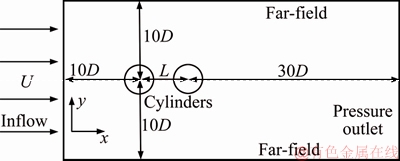
Figure 1 Physical model and computational domain of flow past circular cylinders in tandem
The circular cylinders in this study had slits through their axes, which could be characterized by the slit orientation angle �� and the slit width s, as seen in Figure 2. Also shown in the figure, the angle of boundary layer separation is ��. Both of the two angles were defined in relation to the incoming flow direction, starting from the forward stagnation point. Throughout the study, the slit width remained constant at s/D=0.1.
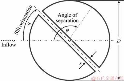
Figure 2 Two-dimensional schematic of a circular cylinder with a slit
The abovementioned physical process could be modeled using the governing equations for continuity:
 (1)
(1)
and the conservation of momentum:
 (2)
(2)
 (3)
(3)
where u and v are the fluid velocity components; x and y are the spatial Cartesian coordinates; t is time; p is pressure.
The computational domain is shown in Figure 1, along with the boundary conditions. The velocity inlet and the top and bottom far-field boundaries were 10 times the cylinder diameter away from the upstream cylinder, whereas the pressure outlet was 3 times the diameter away from the downstream cylinder.
To solve the numerical model, a commercially available computational fluid dynamics application based on the finite volumes method was used. For the numerical procedure, the SIMPLEC algorithm was applied. The discretization of momentum, pressure and transient formulation were carried out using the QUICK scheme, the second order method, and the second order implicit method, respectively. In order to accurately capture the details of the flow structure while also save computational resources, a multi-block grid was generated for the numerical computation, as shown in Figure 3. The grid used very fine mesh where large gradients of the variables such as velocity and pressure were expected (close to the cylinders, in the near-wake region and in the slits), and used a relatively coarse mesh where they were not.
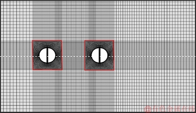
Figure 3 Multi-block grid used for numerical computation
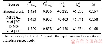
In order to validate the numerical method and determine the suitable mesh count, the flow past a single circular cylinder without a slit was simulated for Re=100, using grids of increasingly finer mesh. Those in the literature are three features from the simulation results, namely the time-averaged (avg) drag coefficient CD (��2FD/ (��U2D), where FD is the drag force on the cylinder), the root-mean-square (rms) of lift coefficient CL (��2FL/(��U2D), where FL is the lift force on the cylinder), and the Strouhal number St (��fD/U, where f is the vortex shedding frequency, which was extracted from the CL data).
It was found that the simulation results represented by the three feature variables stabilized when the mesh count reached approximately 6.5 thousand, at which point St, CD,avg and CL,rms were in good agreement with those in the literature, as given in Table 1.
Table 1 Comparison between simulated and documented results for a single cylinder

Furthermore, validation was performed for the case of two cylinders without slit placed in tandem at distance L/D=5.5. For this scenario, the results stabilized as the mesh count reached approximately 6.8��103, at which point the three feature variables were in good agreement with those in the literature as well, as given in Table 2. The numerical method was thus validated, and the suitable mesh fineness was obtained.
Table 2 Comparison between simulated and documented results for two cylinders in tandem
3 Results and discussion
In this study, while the Reynolds number and the slit width remained constant at Re=100 and s/D=0.1, respectively, L and �� were varied to investigate their effects on the characteristics of the flow past two in-line cylinders with slits. The slit orientations of the two cylinders were not necessarily identical. Instead, eight pairs of orientation combinations were studied, namely 0��-0��, 0��-90��, 30��-30��, 30��-150��, 60��-60��, 60��-120��, 90��-0�� and 90��-90��, along with two cylinders without slit as the baseline.
In order to incorporate the upstream and downstream cylinders into a single framework of notation, one of the two cylinders was arbitrarily designated as the reference, whose centre was at the origin, while the other cylinder was considered to be placed downstream at centre-to-centre distance L. As such, the value of L was positive (resp. negative) when the cylinder in discussion was downstream (resp. upstream) of the reference cylinder. L/D was varied from -6 to 6.
3.1 Flow structure
For the flow past two cylinders placed in tandem and without slit, several flow regimes of different patterns can be classified [13-15]. The actual number of discernible regimes and their boundaries are directly related to Re and the criteria for classification, which includes cylinder-cylinder interference (via their free shear layer, vortices, etc.) and flow structure. In this study, Re=100 falls safely within the low Reynolds number category (<1��103). Also, based on the flow structure classification, which is more palpable than the interference-based method, we clearly observed three distinct flow regimes, namely i) two cylinders acting as an elongated bluff body with alternate vortex shedding, ii) two cylinders acting as an elongated bluff body with a pair of fixed vortices in wake, and iii) alternate vortex shedding from both upstream and downstream cylinders. All the cases in this study could be classified into one of these regimes. An example for each of the three regimes of the flow past two in-line cylinders without slit is shown in Figure 4.
When the cylinders were closer together, the flow in between was relatively stagnant. Two vortices with very slow velocity were formed herein, creating a ��dead region��, through which the interference between the two sides of the flow was minimal. Thus, the two cylinders acted as an elongated bluff body such as an elliptical cylinder or an airfoil. As the cylinders were separated further apart, the elongation increased, which suppressed the shedding vortices in the wake of the downstream cylinder, transforming the alternate vortex shedding into a pair of fixed vortices. As the cylinder distance increased further, the stagnant region became unsteady, leading first to the two intermediate vortices alternating in strength (which was extremely hard to achieve in a semi-steady state, but was observed briefly in a transient state), then to the alternate shedding of vortices from both cylinders.
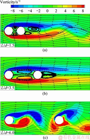
Figure 4 Vorticity field and streamlines of flow
Classification of the flow structures into these three regimes held true regardless of the existence or configuration of slits. However, the transition between regimes was influenced by the slits, which will be demonstrated in detail in the force analysis.
3.2 Force analysis
3.2.1 Drag
The effects of slit configuration and the central distance between cylinders on the time-averaged drag coefficient are shown in Figure 5. Consider first the dashed curve, which denotes the case of no slit. For any given scenario, the upstream cylinder was subjected to larger drag than the downstream cylinder. When the two cylinders acted like a single bluff body, both cylinders experienced a smaller drag. In fact, the drag on the downstream cylinder could be negative when the separation distance was small enough. In regimes i and ii, drag decreased (resp. increased) monotonically with separation distance for the upstream (resp. downstream) cylinder. Apparent was the transition from regime ii to regime iii, as the drag demonstrated a jump between L/D=4.5 and 5.
The general trend of drag vs cylinder distance for the varying slit configurations was similar. However, the transitional point and the values of the drag coefficient were different. For a given regime, drag on the upstream cylinder decreased with increasing slit orientation. This relationship agreed with the previous study [22]. Also, cylinder pairs with asymmetric slit configurations transitioned into regime iii at smaller separations than that for the cylinders with no slit, likely because asymmetry is more prone to generating fluctuations that caused the alternate vortex shedding from the upstream cylinder. On the other hand, for the cases with symmetric slit configuration, the occurrence of regime iii was postponed.
3.2.2 Lift
The effects of slit configuration and the central distance between cylinders on the root mean square of the lift coefficient are shown in Figure 6. Consider the dashed curve. For CL,rms, the two transitions between all three regimes were discernible. When L/D<2, alternating vortex shedding from the downstream cylinder generated very small yet non-zero lift on both cylinders. As the vortex shedding was suppressed, the fixed vortices did not produce noticeable lift, thus CL,rms remained almost zero. When the transition into regime iii occurred between L/D=4.5 and 5, CL,rms jumped to a larger value.
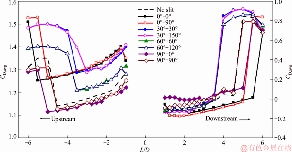
Figure 5 Time-averaged drag coefficient vs cylinder-to-cylinder distance for various slit configurations
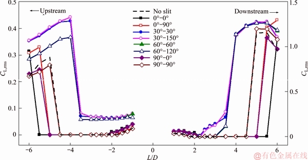
Figure 6 Root mean square of lift coefficient vs cylinder-to-cylinder distance for various slit configurations
This general trend of lift vs cylinder distance held true for the varying slit configurations, though differences were present. For the asymmetric cases, a non-zero lift was always present, which was close to a constant of about 0.8 for the upstream cylinder in regime ii. The trend of CL,rms vs slit orientation was not monotonic, which agreed with the findings of the previous study [22]. Due to the suppression by the downstream cylinder, the lift fluctuation of the upstream cylinder was decreased, resulting in lower CL,rms for the upstream cylinder than that for the downstream. Also, like CD,avg, asymmetric slit configurations facilitated the formulation of alternate vortices shedding from the upstream cylinder, whereas symmetric configurations impeded the transition into regime iii.
3.2.3 Effect of slit orientation
While it is understandable for the asymmetric configurations to induce instability and thus precipitate entrance into regime iii, it is worth discussing the mechanisms for the symmetric configurations to hinder such transition. More specifically, it was observed that hindrance was created in the presence of either one or two in-line slits (��=0��), with two slits inducing more hindrance to transition than one.
It has been pointed out by IGARASHI [6, 7] that the slit exerts influence on the flow past a cylinder mainly through the mechanism of self-injection or suction and blowing of the fluid, which modifies the boundary layer and flow region immediately around the slit openings. An in-line slit, either in the upstream or downstream cylinder, had a significant effect on the intermediate stagnant region, which, if stabilized, would entail a larger cylinder-to-cylinder distance before the transition into regime iii. Thus, it is feasible that the suction and blowing that occur in the stagnant region in a symmetric fashion generated such a stabilizing effect. Alternatively, it could also be argued that in-line slits essentially created a stronger ��connection�� between the two cylinders, strengthening the mechanisms that were already in place without the slits, which made the cylinders act as a single elongated bluff body. Moreover, when both cylinders had in-line slits, the abovementioned impact became more substantial.
3.3 Vortex shedding
3.3.1 Separation angle of boundary layer
Figure 7 shows the time-averaged angle �� at which the boundary layers separate from the cylinder to form either free shear layers or vortices. For the upstream cylinder, the effect of cylinder-to- cylinder distance on the separation angle was minimal, whereas the increase in slit orientation angle increased the separation angle. The case of no slit had identical separation angles for the slit orientation combinations of 60��-60�� and 60��-120��.
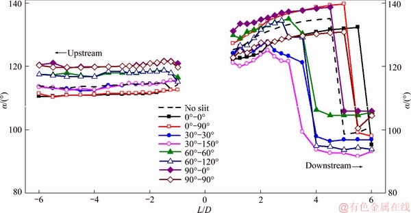
Figure 7 Separation angle vs cylinder-to-cylinder distance for various slit configurations
For the downstream cylinder, the trends were much more complex. However, the correlation between the separation angle and the flow regime was apparent. Taking the case of 30��-30�� as an example, when L/D��2.25, the flow was in regime i, and �� vs L/D was a monotonic increase. Then, at 2.25��L/D��3.5,as regime ii materialized, a mild monotonic decrease could be observed for vs L D. Finally, as the flow transitioned into regime iii, �� plunged downwards.
3.3.2 Vortex shedding frequency
The Strouhal number St, which can be regarded as the dimensionless vortex shedding frequency is given in Figure 8 for varying cylinder separations and slit orientations. The upstream and downstream cylinders are not differentiated here because the shedding frequency (if present) was identical for both cylinders in any given case. The curves in the figure are not continuous because in regime ii the vortices were fixed behind the downstream cylinder, thus shedding frequency could not be extracted. However, in some cases (e.g. 30��-30��, 30��-150��) that fell into the category of regime ii, even though no alternating vortex shedding was present, a very small periodically fluctuating lift was discernible, from which a frequency could be extracted.
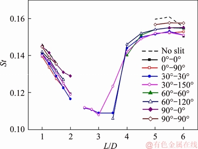
Figure 8 Strouhal number vs cylinder to cylinder distance for various slit configurations
In regimes i and ii, the shedding frequency decreased with cylinder separation. This is because an elongated bluff body suppresses vortex shedding. With the transition into regime iii, the shedding frequency surged, and increased almost monotonically thereafter and tended to the value of a single cylinder. For the upstream cylinders with orientation ��=90��, the shedding frequency was higher than the rest, except the case without slit. The destabilizing effect of the asymmetric slit orientations could also be observed from the figure.
4 Conclusions
The characteristics of flow past two in-line cylinders with slit were numerically investigated. The cylinders had identical diameters and slits with various orientations through their axes. Different cylinder-to-cylinder distance and combinations of slit orientations were investigated. The following conclusions can be made.
1) Three regimes could be clearly discerned based on the flow structure.
2) The drag and lift forces could demonstrate transitions between regimes via features such as jumps in value or turning points.
3) Asymmetric configurations of slits destabilized the stagnant region between cylinders, ushering in regime iii.
4) In-line slits enhanced the stability in the stagnant region between cylinders, hindering the occurrence of regime iii.
5) Vortex shedding features also reflected the existence of the three regimes.
Potential applications of the current findings include wake control of cylinder arrays, novel bluff body design for vortex flowmeter with enhanced and more stable output signals, etc.
References
[1] WILLIAMSON C H. Vortex dynamics in the cylinder wake [J]. Annual Review of Fluid Mechanics, 1996, 28(1): 477-539. DOI: 10.1146/annurev.fl.28.010196.002401.
[2] LI Sai-wei, SUN Zhi-qiang. Harvesting vortex energy in the cylinder wake with a pivoting vane [J]. Energy, 2015, 88: 783-792. DOI: 10.1016/j.energy.2015.05.089.
[3] LI Sai-wei, ZHOU Tian, SUN Zhi-qiang, DONG Zhen-ying. External forced convection from circular cylinders with surface protrusions [J]. International Journal of Heat and Mass Transfer, 2016, 99: 20-30. DOI: 10.1016/ j.ijheatmasstransfer.2016.03.092.
[4] SUN Zhi-qiang, LI Zhi-yong, JIANG yun, ZHOU Hong-liang. Influence of bluff body shape on wall pressure distribution in vortex flowmeter [J]. Journal of Central South University, 2013, 20(3): 724-729. DOI: 10.1007/s11771- 013-1540-9. DOI: 10.1016/j.ijheatmasstransfer.2017.04.020.
[5] ZHOU Tian, LIU Xu, LI Yuan, SUN Zhi-qiang, ZHOU Jie-min. Dynamic measurement of the thermal conductiviey of phase change materials in the liquid phose near the melting point [J]. International Journal of Heat and Mass Transfer, 2017, 111: 631-641. DOI: 10.1016/ j.ijheatmasstransfer.2017.04.020.
[6] IGARASHI T. Flow characteristics around a circular cylinder with a slit: 1st report, flow control and flow patterns [J]. Bulletin of JSME, 1978, 21(154): 656-664. DOI: 10.1299/ jsme1958.21.656.
[7] IGARASHI T. Flow characteristics around a circular cylinder with a slit: 2nd report, effect of boundary layer suction [J]. Bulletin of JSME, 1982, 25(207): 1389-1397. DOI: 10.1299/ jsme1958.21.656.
[8] POPIEL C, ROBINSON D, TURNER J. Vortex shedding from a circular cylinder with a slit and concave rear surface [J]. Applied Scientific Research, 1993, 51(1, 2): 209-215. DOI: 10.1007/BF01082539.
[9] OLSEN J, RAJAGOPALAN S. Vortex shedding behind modified circular cylinders [J]. Journal of Wind Engineering and Industrial Aerodynamics, 2000, 86(1): 55-63. DOI: 10.1016/S0167-6105(00)00003-9.
[10] PENG B, MIAU J, BAO F, WENG L, CHAO C, HSU C. Performance of vortex shedding from a circular cylinder with a slit normal to the stream [J]. Flow Measurement and Instrumentation, 2012, 25: 54-62. DOI: 10.1016/ j.flowmeasinst.2011.07.003.
[11] GAO Dong-lai, CHEN Wen-li, LI Hui, HU Hui. Flow around a circular cylinder with slit [J]. Experimental Thermal and Fluid Science, 2017, 82: 287-301. DOI: 10.1016/ j.expthermflusci.2016.11.025.
[12] GAO Dong-lai, CHEN Wen-li, LI Hui, HU Hui. Flow around a slotted circular cylinder at various angles of attack [J]. Experiments in Fluids, 2017, 58(10): 132. DOI: 10.1007/ s00348-017-2417-8.
[13] ZDRAVKOVICH M. Review of flow interference between two circular cylinders in various arrangements [J]. Journal of Fluids Engineering, 1977, 99(4): 618-633. DOI: 10.1115/ 1.3448871.
[14] SUMNER D. Two circular cylinders in cross-flow: A review [J]. Journal of Fluids and Structures, 2010, 26(6): 849-899. DOI: 10.1016/j.jfluidstructs.2010.07.001.
[15] ZHOU Y, ALAM M M. Wake of two interacting circular cylinders: A review [J]. International Journal of Heat and Fluid Flow, 2016, 62: 510-537. DOI: 10.1016/ j.ijheatfluidflow.2016.08.008.
[16] BLOOR M S. The transition to turbulence in the wake of a circular cylinder [J]. Journal of Fluid Mechanics, 1964, 19(2): 290-304. DOI: 10.1017/S0022112064000726.
[17] HENDERSON R D. Details of the drag curve near the onset of vortex shedding [J]. Physics of Fluids, 1995, 7(9): 2102-2104. DOI: 10.1063/1.868459.
[18] NORBERG C. Pressure forces on a circular cylinder in cross flow [C]//ECKELMANN H, GRAHAM J M R, HUERRE P, MONKEWITZ P A. Bluff-Body Wakes, Dynamics and Instabilities. International Union of Theoretical and Applied Mechanics. Berlin, Heidelberg: Springer, 1993. DOI: 10.1007/978-3-662-00414-2_60.
[19] WILLIAMSON C H. Oblique and parallel modes of vortex shedding in the wake of a circular cylinder at low Reynolds numbers [J]. Journal of Fluid Mechanics, 1989, 206: 579-627. DOI: 10.1017/S0022112089002429.
[20] MITTAL S, KUMAR V, RAGHUVANSHI A. Unsteady incompressible flows past two cylinders in tandem and staggered arrangements [J]. International Journal for Numerical Methods in Fluids, 1997, 25(11): 1315-1344. DOI: 10.1002/(SICI)1097-0363(19971215)25:11<1315::AID- FLD617>3.0.CO;2-P.
[21] DING H, SHU C, YEO K, XU D. Numerical simulation of flows around two circular cylinders by mesh-free least square�\based finite difference methods [J]. International Journal for Numerical Methods in Fluids, 2007, 53(2): 305-332. DOI: 10.1002/fld.1281.
[22] XING Peng-fei, SUN Zhi-qiang. Characteristics of flow around circular cylinder with slit at low Reynolds number [J]. Journal of Central South University (Science and Technology), 2019, 50(4): 990-997. (in Chinese)
(Edited by YANG Hua)
���ĵ���
����ŵ������˫����Բ�����������������о�
ժҪ������ͨ����ֵ�����о��˲�������˫Բ�������п����Ӱ�졣ͨ���ı�Բ��������ļ���Լ��������б�ǣ���ʾ�������ṹ��Բ�������������Լ���������ı仯���ƣ����ִ���������̬�����Ǽ���ת�����������������ļ���仯���֡�����������ǶԳƵĿ����Բ�������ֹ���и������ã���˳���Ŀ�����ͨ������ֹ�����ȶ����ý�����Բ������ϵ����������һ����չ�Ķ��壬�������ڽϳ�Բ���������Ȼ��Ч�����ϸ��ź��ȶ�������Ӱ����̬���ת������������Ҳ���ܲ�ͬ�����Բ������Ӱ�졣
�ؼ��ʣ�����˫Բ��������Բ�����������䣻����β��
Foundation item: Project(51576213) supported by the National Natural Science Foundation of China; Project(2017JJ1031) supported by Hunan Provincial Natural Science Foundation of China; Project(CSUZC201921) supported by the Open Sharing Fund for the Large-scale Instruments and Equipments of Central South University, China; Project(2019zzts536) supported by the Fundamental Research Funds for the Central Universities, China
Received date: 2019-06-27; Accepted date: 2019-07-05
Corresponding author: LI Sai-wei, PhD; Tel: +86-731-88879863; E-mail: saiwei@csu.edu.cn; ORCID: 0000-0002-5849-8062

