J. Cent. South Univ. (2016) 23: 2542-2549
DOI: 10.1007/s11771-016-3315-6

Numerical analysis of loaded stress and central displacement of deep groove ball bearing
YANG Lei(杨磊)1, 2, DENG Song(邓松)1, 2, 3, LI Hong-xing(李红星)3
1. Hubei Key Laboratory of Advanced Technology for Automotive Components, Wuhan University of
Technology, Wuhan 430070, China;
2. Hubei Collaborative Innovation Center for Automotive Components Technology, Wuhan University of
Technology, Wuhan 430070, China;
3. Zhejiang Tianma Bearing Co. Ltd., Hangzhou 310015, China
 Central South University Press and Springer-Verlag Berlin Heidelberg 2016
Abstract: The aim of this work is to develop a three-dimensional model of deep groove ball bearing to investigate the loaded stresses and central displacements of bearing rings. The equivalent stresses and central displacements of bearing rings are obtained based on the simulated analysis. Moreover, several parameters, such as load magnitude, raceway groove curvature radius (RGCR), thicknesses of outer and inner rings, are varied to investigate their effects on the equivalent stresses and central displacements of bearing rings. Research results provide useful guidelines for determining the design parameters.
Key words: deep groove ball bearing; equivalent stress; central displacement
1 Introduction
Rolling bearings are crucial component of any rotating machinery and have wide variety of application such as household appliances, automobiles, machine tools, space vehicles. The reasonable design of rolling bearings is helpful for providing the high efficiency, lower friction and more reliable operation under adverse operating condition. So, it is of great importance to study the loaded stress and central displacement of bearing rings under various design parameters.
At present, some scholars have carried out the researches on the contact force, stiffness, load distribution and gyroscopic torque of bearings. KURVINEN et al [1-2] increased the complexity of a numerical model of ball bearings to study the effect of the rotation speed, centrifugal and gyroscopic forces and bearing stiffness coefficient on the bearing performance. For the high-speed angular contact ball bearing, the relationship between the gyroscopic torque of a rolling element and the coefficient of friction between the rolling element and groove was analyzed and the internal load of this ball bearing that sustains a purely axial load was calculated [3-4]. GUO and PARKER [5] and SHENG et al [6] developed an analytic model based on the differentiation of implicit function to improve the calculation of the speed-varying stiffness, and the comparison between the results from the numerical method and the proposed method was carried out. The different types of rolling bearing stressing were studied and the stress distribution in the material was analyzed under the rolling contact area, and it demonstrates the impact of the bearing lubrication and coating as well as the effect of additives on the attainable life and wear [7-8]. A two-degree freedom nonlinear model of a rotor- bearing system on rolling element bearings was developed to study the effects of unbalance, support stiffness and clearance on the performance of rolling bearings [9-10]. A computational model of a double row four-point contact ball bearing, subjected to the combined radial, axial and overturning moment loadings and considering the clearance of bearing, was established to analyze the effect of clearance on the startup torque, rotation precision and stiffness of bearing [11-12]. Moreover, the contact stress [13-14], frictional heat generation [15], heat transfer processes and thermal expansion [16], traction forces between balls and raceways [17], and stiffness and damping characteristics [18] of rolling bearings were also taken seriously. The manufacture method of bearing rings is also emphasized [19-25]. However, it should be noted that a majority of the studies above were primarily concentrated on the stress states, geometric accuracy loss, frictional heat generation, and carrying capacity of bearings under the working conditions, while little attention was paid to the effect of design parameters of the bearing ring on the loaded stress and central displacement of rolling bearings. Therefore, it is of great importance to study the loaded stress and central displacement of rolling bearings under the various parameters such as load magnitude, RGCR and thicknesses of inner and outer rings.
In this work, a three-dimensional numerical model of the deep groove ball bearing is developed under the ANSYS software environment. Then, the effect of radial and axial loads on the equivalent stress and central displacement of inner and outer rings is analyzed. Design parameters, such as RGCR, and thicknesses of inner and outer rings, are varied to investigate their effects on the equivalent stresses and central displacement of inner and outer rings.
2 Development of numerical model
In this work, a 6208 (bearing designation, SKF) deep groove ball bearing is considered the research object. The basic geometric data are shown in Table 1. A plane sketch of the geometric model is presented in Fig. 1. Several parameters, such as radial load Fr, axial load Fa, outer RGCR re, inner RGCR ri, thickness of outer ring Te, and thickness of outer ring Ti, are varied to calculate the equivalent stresses and central displacement of bearing rings.
The numerical model is developed as shown in Fig. 2. The material used in this study is GCr15 steel, and the main parameters are: elastic modulus E= 2.10×10⁵ MPa, Poisson ratio ν=0.3, material density ρ′= 7.85×10³ kg/m3, and friction coefficient between steel balls and raceways of bearing rings is 0.15. The bearing ring is meshed with 20-noded quadratic hexahedron elements. To get accurate stress and strain, the refined mesh is created in the bearing raceways. The element size near raceways is an approximately 1-mm cube. The steel balls are defined as rigid bodies. Nodes on the cylinder surface of outer ring contacting with bearing seat are considered as fixed. Nodes on the semicylinder surface of inner ring contacting with shaft are selected to exert the radial load Fr (3.0 kN) and axial load Fa (0). In a real contact between the steel ball and the bearing ring, the pressure distribution is often complex and highly dependent on the exact profiles of the steel ball and bearing ring as well as their relative positions. Using the boundary element modeling approach, it is possible to directly simulate the ball contacting the bearing ring. Hence, it is convenient to obtain a real pressure distribution on the raceway surface by defining the contact surfaces within the model.
Table 1 Basic geometrical data of 6208 deep groove ball bearing

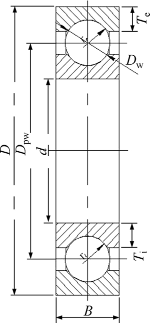
Fig. 1 Plane sketch of 6208 deep groove ball bearing

Fig. 2 Simulated model of 6208 deep groove ball bearing
After accomplishing the simulated model of 6208 deep groove ball bearing, the numerical analysis can be carried out. The von Mises stress distribution of inner and outer rings is acquired as shown in Fig. 3.
3 Validation of numerical model
To validate the numerical model, the contact stress distribution of the inner ring based on the numerical analysis is compared with that calculated from the Hertzian theory. Figure 4 shows a comparison of the contact stress distribution between the numerical analysis and the Hertzian theory on the raceway surface when the radial load is 3 kN. The vertical axis indicates the contact stress on the contact area of the bearing ring when the minor radius of the contact ellipse is zero. The horizontal axis indicates the distance from the contact zone centre to the contact half-width. From Fig. 4, it can be seen that the contact stress distribution is in good agreement with the ideal distribution of the Hertzian theory. The contact half-width of the numerical analysis is 1.86 mm, and the ideal half-width is 1.961 mm, as calculated from the Hertzian theory. The half-width is different because it is not a point contact but a contact arc between the steel ball and the raceway surface. The maximum contact stress (σs) calculated from the numerical analysis is greater than the ideal value (σh) calculated from the Hertzian theory because there is an exterior tangency between the steel ball and the inner raceway surface, which results in reduction of the contact area with respect to the point contact. The maximum relative error is 9.51%. Therefore, the numerical analysis is proved to be reliable based on the comparison of the contact stress distribution between the numerical analysis and the Hertzian theory.
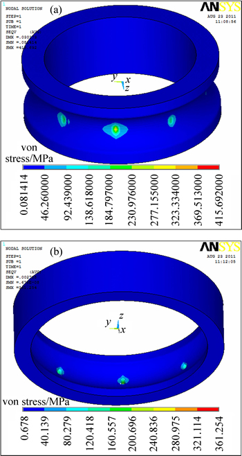
Fig. 3 von Mises stress distribution:
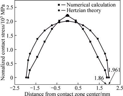
Fig. 4 Contact stress distribution on raceway surface
4 Analysis and discussion
Based on this validated model, several parameters, such as radial load Fr, axial load Fa, outer RGCR re, inner RGCR ri, thickness of outer ring Te, and thickness of outer ring Ti, are varied to calculate the equivalent stresses and central displacement of bearing rings. Three distinct conditions are detailed below.
Condition 1: to study the effect of RGCR on the equivalent stresses and central displacement of bearing rings, RGCRs ri=re={6.54, 6.79, 7.04, 7.29, 7.54} (mm), are varied, respectively. The other remaining parameters stated in section 2 remain unchanged.
Condition 2: to vary the thicknesses of inner and outer rings for analyzing the equivalent stresses and central displacement of bearing rings. Te=Ti={2.0, 2.5, 3.0, 3.65} (mm) are selected, respectively. The other remaining parameters stated in section 2 remain unchanged.
Condition 3: to study the effect of radial and axial loads on the equivalent stresses and central displacement of bearing rings, radial load Fr={1.5, 2.0, 3.0, 4.0, 5.0} (mm) and axial load Fa={0, 0.5,1.0, 1.5} (mm) are selected, respectively. The other remaining parameters stated in section 2 remain unchanged.
4.1 Equivalent stresses and central displacements of bearing rings under condition 1
Figure 5(a) describes the effect of inner RGCR on the maximum equivalent stresses of inner and outer rings. It is clear that the maximum equivalent stress of the inner ring is gradually increased with increasing the inner RGCR. For the outer ring, the maximum equivalent stress is firstly reduced and then has no obvious change with the increase of the inner RGCR. In Fig. 5(b), it can be seen that when the outer RGCR is increased, the maximum equivalent stress of the outer ring is increased gradually. But for the inner ring, it decreaseds at the outer RGCR of 6.79 mm and then no an obvious change occurs. This is because when ri/re is 6.79 mm, the contacts between the steel balls and the inner and outer raceways increase so that the load exerted to the steel balls is relieved. Thus the maximum equivalent stress of outer/inner ring is reduced. For other increased ri/re, the contact area between the balls and the raceways is governed by RGCR, as follows [26]:
 (1)
(1)
 (2)
(2)
where Q is the load applying to the ball; a is the semi- major axis in the contact area; b is the semi-minor axis; μ′ and η′ depend on the ball bearings; ∑ρ is the curvature sum of the ball and the bearing ring.
 (3)
(3)
 (4)
(4)
 (5)
(5)
where α is the contact angle; r is ri or re; Dpw is the diameter of ball’s centre in the bearing. For Eq. (3), the above sign is suitable for the contact between a ball and an inner ring and the below sign is used for the contact of a ball with an outer ring.

Fig. 5 Effect of RGCR variation on maximum equivalent stress:
According to these equations above, it can be found that the curvature sum ∑ρ is increased with increasing RGCR, resulting in the reduction of a and b, thus the contact area decreases. The enhance of the stress is attributed to the reduction of the contact area. Yet the inner RGCR has no influence on the stress of the outer ring, thus the maximum equivalent stress of the outer ring has no obvious change when ri is large than 6.79 mm. Similarly, the outer RGCR has no effect on the equivalent stress of the inner ring. Therefore, when ri/re is 6.79 mm, the RGCR has a particular effect on the maximum equivalent stress of the outer/inner ring.
Figure 6 shows the central displacement of the inner ring under the various inner/outer RGCR. From Fig. 6, it can be seen that the central displacement of the inner ring is reduced when ri/re is 6.79 mm, and then it increases with increasing the inner/outer RGCR. This is because the contacts between the steel balls and the inner and outer raceways increase so that the load exerted to the steel balls is relieved. Thus, the deformation of outer/inner ring is reduced when ri/re is 6.79 mm. For other RGCR, the increase of the central displacement is attributed to the relationship of the central displacement with RGCR, as follows [26]:
 (6)
(6)
where δn is the central displacement of the inner ring; δi is the deformation between steel balls and the inner ring;δe is the deformation between steel balls and the outer ring; Cδ is the elastic coefficient; CE is the material coefficient. Subscript i/e indicates the inner/outer ring. According to Eq. (6), the central displacement of the inner ring is gradually increased with increasing the ri/re, because the large deformation of bearing rings occurs attributed to the reduction of contact areas. Therefore, at the inner and outer RGCR of 6.79 mm, the central displacement of the inner ring is not in conformity with Eq. (6).
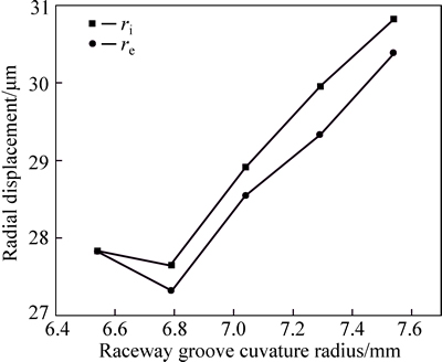
Fig. 6 Central displacement of inner ring under variation of inner/outer RGCR
4.2 Equivalent stresses and central displacements of bearing rings under condition 2
Figure 7 represents the maximum equivalent stress of bearing rings under various thicknesses of bearing rings. From Fig. 7(a), it can be seen that the maximum equivalent stress of the outer ring is gradually decreased with reducing the thickness of the inner ring. For the inner ring, the equivalent stress is reduced gradually until the thickness is depressed to 2.5 mm, and then it is enhanced at the thickness of 2.0 mm. This is because when the thickness of the inner ring is ranged from 3.65 mm to 2.5 mm, more steel balls are contacted with the raceways of the inner and outer rings due to the smaller central displacement of the inner ring (shown in Fig. 8), which induces the drop of the equivalent stress of the inner and outer rings. When Ti is 2.0 mm, the stiffness of the inner ring is significantly weakened so that the large deformation occurs at the inner ring (that is, a large central displacement appears, shown in Fig. 8), thus the maximum equivalent stress of the inner ring is enhanced at the thickness of 2.0 mm. In Fig. 7(b), the maximum equivalent stress of the inner ring is firstly weakened, and then it is slowly increased when the thickness of the outer ring is varied. For the outer ring, the variation of the equivalent stress shows the typical positive parabolic shape with changing the thickness of the outer ring. This phenomenon has the same reason with that in Fig. 7(a), that is, the contact pairs between the steel balls and the raceways of inner and outer rings are increased at the thickness of 3.0 mm. When Te is 2.0 mm, the rise of the equivalent stress for the outer ring is attributed to the drop of the stiffness of outer ring. Therefore, the contact pairs and thickness of bearing rings have important roles on the maximum equivalent stress. It is of great importance to properly weaken the thickness of bearing rings to improve the contact between balls and bearing raceways.
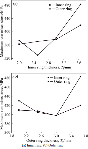
Fig. 7 Effect of thickness of bearing rings on maximum equivalent stress:
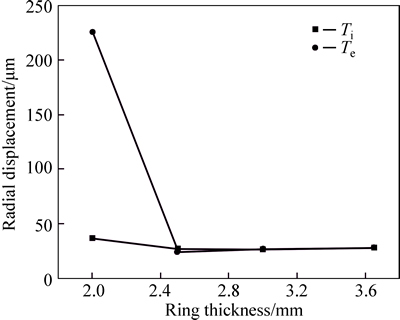
Fig. 8 Central displacement of inner ring under various thicknesses of bearing rings
The central displacement of the inner ring under various thicknesses of bearing rings is shown in Fig. 8. It is clear that no an obvious displacement of the inner ring occurs when Ti/Te is ranged from 3.65 mm to 2.5 mm. At the thickness of 2.0 mm, the central displacement of the inner ring is sharply boosted. This is mainly because more balls hold up the inner ring at the thickness of 2.5-3.65 mm. Yet when Ti/Te is 2.0 mm, the weak stiffness of bearing rings causes the large deformations of the inner and outer rings despite the contacts between balls and bearing raceways have no change. Therefore, it is crucial to design proper thicknesses of bearing rings for lowering the central displacement.
4.3 Equivalent stresses and central displacements of bearing rings under condition 3
Figure 9(a) presents the variation on the maximum equivalent stress of the inner ring under the radial and axial loads. It is clear from Fig. 9(a) that the maximum equivalent stress increases linearly with the increase of the radial and axial loads. When no the axial load exists on the bearing rings, the maximum equivalent stress of the inner ring increases linearly with the increase of the radial load. Equally, when the radial load has no change on the bearing rings, the maximum equivalent stress is increased with enhancing the axial load. For the outer ring, the variation on the maximum equivalent stress has the same variation as that of the inner ring under the combination of radial and axial loads. Therefore, the increases of axial and radial loads simply strengthen the equivalent stresses of bearing rings.

Fig. 9 Variation of maximum equivalent stress of bearing rings under various radial and axial loads:
Figure 10 shows the radial and axial displacements under various radial and axial loads. From Fig. 10(a), it can be seen that the central displacement of the inner ring in the axial direction is 0 when the axial load is 0. When the radial load has no change, the axial displacement is strengthened with increasing the axial load. This is because no contacts between the upper part of the inner ring and steel balls occur so that a large axial deviation of the inner ring appears, as shown in Fig. 11. With increasing the radial load, the axial displacement is gradually descended, which is attributed part of the inner ring and steel balls resulting in the drop to the factor that more contacts occur between the lower of the axial deviation of inner ring. In Fig. 10(b), it can be seen that when the axial load is 0, the radial displacement of the inner ring gradually increases with intensifying the radial load. When the axial load exists on the inner ring, the radial displacement is larger than that at the axial load of 0. This is because the deviation of the inner ring causes a small radial displacement (shown in Fig. 11). Therefore, the deviation of the inner ring plays an important role in the central displacement in the radial and axial directions.
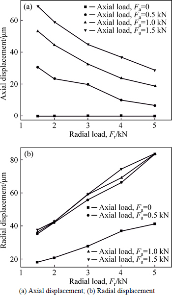
Fig. 10 Central displacement of inner ring under various loads:
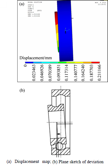
Fig. 11 Deviation of inner ring:
5 Conclusions
6208 deep groove ball bearing is considered the research object and its three-dimensional numerical model is developed to study the loaded stress and central displacement of rolling bearings. Based on the numerical analysis, the effect of radial and axial loads on the equivalent stress and central displacement of inner and outer rings is analyzed. Design parameters, such as RGCR, and thicknesses of inner and outer rings, were varied to investigate their effects on the equivalent stresses and central displacement of inner and outer rings. The study results are shown as follows:
1) The maximum equivalent stress of inner/outer ring gradually increases with increasing the inner RGCR. Yet, the contacts between the steel balls and the inner and outer raceways increase so that the equivalent stress of outer/inner ring is relieved when ri/re is 6.79 mm.
2) The central displacement of the inner ring gradually increases with increasing the ri/re. But at the inner and outer RGCR of 6.79 mm, the central displacement of the inner ring is not in conformity with Eq. (6) due to the increase of the contact pairs between the steel balls and the inner and outer raceways.
3) When Te/Ti is 2.0 mm, the rise of the equivalent stress for the outer/inner ring is attributed to the drop of the stiffness of outer ring. When the thickness of the inner/outer ring is ranged from 3.65 to 2.5 mm, more steel balls are contacted with the raceways of the inner and outer rings so that the drop of the equivalent stresses of the inner and outer rings occurs. For the central displacement, it has no obvious change when Ti/Te is ranged from 3.65 mm to 2.5 mm, but it is sharply boosted at the thickness of 2.0 mm.
4) The maximum equivalent stress of the inner/outer ring increases linearly with the increase of the radial load. Moreover, a deviation of the inner ring occurs so that the radial and axial displacements appear.
Acknowledgement
The authors would like to thank the National Natural Science Foundation of China (No. 51605354), the Fundamental Research Funds for the Central Universities (WUT: 2015IVA021), the Innovative Research Team Development Program of Ministry of Education of China (No. IRT13087), and the High-end Talent Leading Program of Hubei Province (No. 2012- 86), China for the support given to this research.
References
[1] KURVINEN E, SOPANEN J, MIKKOLA A. Ball bearing model performance on various sized rotors with and without centrifugal and gyroscopic forces [J]. Mechanism and Machine Theory, 2015, 90: 240-260.
[2] NAKHAEINEJAD M, BRYANT M D. Dynamic modeling of rolling element bearings with surface contact defects using bond graphs [J]. Journal of Tribology, 2011, 133: 1-12.
[3] ZHAO C J, YU X K, HUANG Q X, GE S D, GAO X. Analysis on the load characteristics and coefficient of friction of angular contact ball bearing at high speed [J]. Tribology International, 2015, 87: 50-56.
[4] COUSSEAU T,  B, CAMPOS A, SEABRA J. Friction torque in grease lubricated thrust ball bearings [J]. Tribology International, 2011, 44(5): 523-531.
[5] GUO Y, PARKER R G. Stiffness matrix calculation of rolling element bearings using a finite element/contact mechanics model [J]. Mechanism and Machine Theory, 2012, 51: 32-45.
[6] SHENG X, LI B Z, WU Z P, LI H Y. Calculation of ball bearing speed-varying stiffness [J]. Mechanism and Machine Theory, 2014, 81: 166-180.
[7] EBERT F J. Fundamentals of design and technology of rolling element bearings [J]. Chinese Journal of Aeronautics, 2010, 23(1): 123-136.
[8] BRANCH N A, ARAKERE N K, FORSTER N, VAUGHN S. Criticalstressesand strains at the spall edge of a case hardenedbearingdue toballimpact [J]. International Journal of Fatigue, 2013, 47: 268-278.
[9] KAPPAGANTHU K, NATARAJ C. Nonlinear modeling and analysis of a rolling element bearing with a clearance [J]. Communications in Nonlinear Science and Numerical Simulation. 2011, 16(10): 4134-4145.
[10] ALBERT V K, ANDREY A K, RADOSLAV K. Character of distribution of the load between theballsin theballbearingsunder the action combined of external load [J]. Mechanism and Machine Theory, 2014, 81: 54-61.
[11] WANG Y S, YUAN Q Q. Contact force distribution and static load-carrying capacity of large size double row four-point contact ball bearing [J]. Defence Technology, 2013, 9: 229-236.
[12] WANG Y S, CAO J W. Determination of the precisestatic load- carrying capacity of pitch bearings based on static models considering clearance [J]. International Journal of Mechanical Sciences, 2015, 100: 209-215.
[13] YOU H Y, ZHU C X, LI W X. Contact analysis on large negative clearance four-point contactballbearing [J]. Procedia Engineering, 2012, 37: 174-178.
[14] AYDIN G, JASON T, DREYER R S. Effect ofbearingpreloads on the modal characteristics of a shaft-bearingassembly: Experiments on double row angular contactballbearings [J]. Mechanical Systems and Signal Processing, 2012, 31: 176-195.
[15] TAKABI J, KHONSARI M M. Experimental testing and thermal analysis of ball bearings [J]. Tribology International, 2013, 60: 93-103.
[16] JIN C, WU B, HU Y. Heat generation modeling of ball bearing based on internal load distribution [J]. Tribology International, 2012, 45: 8-15.
[17] WANG Y L, WANG W Z, ZHANG S G, ZHAO Z Q. Investigation of skidding in angular contact ball bearings under high speed [J]. Tribology International, 2015, 92: 404-417.
[18] JACOBS W, BOONEN R, SAS P, MOENS D. The influence of the lubricant film on the stiffness and damping characteristics of a deep groove ball bearing [J]. Mechanical Systems & Signal Processing, 2014, 42(s1/2): 335-350.
[19] QIAN D S, PAN Y. 3D coupled macro-microscopic finite element modelling and simulation for combined blank-forging and rolling process of alloy steel large ring [J]. Computational Materials Science. 2013, 70: 24-36.
[20] QIAN D S, ZHANG Z Q, HUA L. An advanced manufacturing method for thick-wall and deep-groove ring-combined ring rolling [J]. Journal of Materials Processing Technology, 2013, 213: 1258- 1267.
[21] QIAN D S, HUA L, DENG J D. FE analysis for radial spread behavior in three-roll cross rolling with small-hole and deep-groove ring [J]. Transactions of Nonferrous Metals Society of China, 2012, 22: 247-253.
[22] ZHOU G, HUA L, QIAN D S, SHI D F, LI H X. Effects of axial rolls motions on radial-axial rolling process for large-scale alloy steel ring with 3D coupled thermo-mechanical FEA [J]. International Journal of Mechanical Science, 2012, 59: 1-7.
[23] HAN X H, HUA L. Friction behaviors in cold rotary forging of 20CrMnTi alloy [J]. Tribology International, 2012, 55: 29-39.
[24] HAN X H, HUA L. 3D FE modeling of cold rotary forging of a ring workpiece [J]. Journal of Materials Processing Technology, 2009, 209: 5353-5362.
[25] HAN X H, HUA L, ZHUANG W H, ZHANG X C. Process design and control in cold rotary forging of non-rotary gear parts [J]. Journal of Materials Processing Technology, 2014, 214: 2402-2416.
[26] American National Standards Institute (ANSI/ABMA) Std 20-1996. Radial bearings of ball, cylindrical roller, and spherical roller types [S].
(Edited by YANG Hua)
Received date: 2015-11-09; Accepted date: 2016-05-23
Corresponding author: DENG Song, PhD, Lecturer; Tel: +86-15827616974; Fax: +86-27-83875634; E-mail: guoheng0722@126.com

