Trans. Nonferrous Met. Soc. China 25(2015) 1144-1150
Long-term corrosion behavior of HVOF sprayed FeCrSiBMn amorphous/nanocrystalline coating
Yu-jiao QIN, Yu-ping WU, Jian-feng ZHANG, Wen-min GUO, Sheng HONG, Li-yan CHEN
Institute of Metals and Protection, College of Mechanics and Materials, Hohai University, Nanjing 210098, China
Received 27 May 2014; accepted 17 November 2014
Abstract: A FeCrSiBMn amorphous/nanocrystalline coating with 700 ҰМm in thickness and 0.65% in porosity, was prepared by high velocity oxygen fuel (HVOF) spraying process. The long-term corrosion behavior of the FeCrSiBMn coating was evaluated by potentiodynamic polarization and electrochemical impedance spectroscopy (EIS) tests in a 3.5% NaCl solution with a hard chromium coating as a reference. The FeCrSiBMn coating exhibited higher corrosion potential and lower corrosion current density than the hard chromium coating. The pore resistance (Rp) and charge transfer resistance (Rct) of FeCrSiBMn coating were higher than those of the hard chromium coating. In addition, after immersion in the NaCl solution for 28 d, only small pores in the FeCrSiBMn coating were observed. All the results indicated that the FeCrSiBMn coating held superior corrosion resistance to the hard chromium coating. This could be attributed to the dense structure, low porosity and amorphous/nanocrystalline phases of the FeCrSiBMn coating.
Key words: HVOF spraying; coating; Fe-based amorphous/nanocrystalline; corrosion resistance
1 Introduction
The concept of using surface coatings by plating or thermal spraying to protect many engineering components from corrosion is widespread [1-3]. However, the substitution of plating, especially electroplating, is now becoming more and more necessary due to the strict requirement of pollution prevention and control [3-5]. With the merits of environmental friendliness and high efficiency, the high velocity oxygen fuel (HVOF) technology is taken as one of the most competitive thermal spray technologies to substitute for the hard chromium plating technology [6-8]. Therefore, many researchers have used HVOF technology to fabricate wear or corrosion-resistant coatings [9-16], among which Fe-based amorphous/ nanocrystalline coating is the most promising one due to the unique combination of high hardness/strength, outstanding corrosion resistance and relatively low material cost.
BAKARE et al [17] prepared HVOF sprayed Fe43Cr16Mo16C15B10 amorphous coating, which has better corrosion resistance compared to its crystalline form in 0.5 mol/L H2SO4 and 3.5% NaCl electrolytes. YANG et al [18] and ZHANG et al [19] found that Fe48Cr15 Mo14C15B6Y2 amorphous coating had excellent corrosion resistance in 3.5% NaCl solutions and the corrosion resistance of the coating deteriorated with the increase in the amount of crystalline phase. Besides, the corrosion resistance of the coating was closely related to the wetting behavior and the coatings with hydrophobicity exhibited a better corrosion resistance. WANG et al [20,21] made a systematic study on the corrosion resistance of Fe54.2Cr18.3Mo13.7Mn2.0W6.0B3.3C1.1Si1.4 amorphous coatings. They noted that the amorphous coating showed better corrosion resistance than stainless steel 304 in NaCl solution, and the corrosion resistance of the amorphous coatings increased with the increase of the coating thickness and decreased with with the increase of the concentration of NaCl solution. In addition, the corrosion resistance of the amorphous coating was dominant by the amorphous phase fraction when the porosity was less than 1.21%, while it was dominant by porosity when the porosity was higher than 1.21%. In our early studies, the FeCrSiBMn coating was prepared by HVOF spray technology [9,22,23], which consisted of amorphous phase, nanocrystalline grains, and several kinds of borides and carbides. Due to the existence of the amorphous phase and nanocrystalline grains with a size of 10-50 nm, this coating exhibited higher resistance to cavitation erosion in fresh water than a hydromachine material ZG06Cr13Ni5Mo martensite stainless steel.
To the best of our knowledge, many studies have been focused on the evaluation of the corrosion behavior of the Fe-based amorphous coating after immersion of 1 h [6,12-15,17-21]. It is known that the attack from corrosive environments would like to severely decrease the service life of the protective coating with operation time. Thus, the characterization of the long term corrosion behavior and the corrosion mechanism of the Fe-based coating should be necessary. However, the related research work on this point is still limited [24,25]. In the present work, the long-term (up to 28 d) corrosion behavior of the Fe-based coating was presented with hard chromium coating (by plating) as a reference material. The effects of immersion time in a 3.5% NaCl solution on the potentiodynamic polarization curves and electrochemical impedance spectroscopy (EIS) were discussed, and the related mechanism was proposed.
2 Experimental
2.1 Preparation of coating
The nominal composition of the Fe-based alloy powder (44.7%Cr-1.98%Si-2.97%B-0.08%Mn and the balance Fe, mass fraction) with the particle size of 15-45 ҰМm was used as feedstock one. The Q235 low carbon steel was served as substrate with dimensions of 35 mmЎБ35 mmЎБ6 mm. Before the spraying process, the substrate was machined and polished, then degreased by acetone, dried in air, and grit-blasted. A Tafa-JP8000 spray system was employed for spraying. The spraying distance was 330 mm, the flow rate of kerosene was 0.47 L/min, the flow rate of oxygen was 869 L/min, the powder feed rate was 5.5 r/min and the traverse velocity of spray gun was 280 mm/s.
2.2 Testing methods
The phase composition of the powder and coating were investigated by X-ray diffraction (XRD, Bruker D8-Advanced, Germany) with a copper KҰБ radiation. The microstructures of the feedstock powder and as-sprayed coating were observed by scanning electron microscope (SEM, Hitachi S-3400N, Japan). The porosity of the coatings was calculated through OLYMPUS-BX51M optical microscope combined with DT-2000 image analysis software, and five tests were repeated for each average value.
The corrosion behavior of the FeCrSiBMn amorphous/nanocrystalline coating and hard chromium coating was evaluated by electrochemical measurement on a PARASTAT 2273 electrochemical site. Prior to the electrochemical measurements, the samples were successively ground on 240, 400, 600, 800, 1000 and 1200 mesh grade silicon carbide grit papers, then degreased in acetone, washed in distilled water, and dried in air. Electrochemical measurements were performed with a standard three-electrode system using a platinum counter electrode and a saturate calomel reference electrode. The specimen served as the working electrode and was exposed only to the area of 1 cm2. All experiments were carried out in 3.5% NaCl solution at 298 K. After being immersed for 1 h, the open-circuit potential became almost steady and the experiments started. Potentiodynamic polarization swept from -0.25 to +1.5 V relative to the open circuit potential at a fixed rate of 1 mV/s. Electrochemical impedance spectroscopy (EIS) measurements were performed using a sinusoidal potential perturbation of 10 mV in a frequency range of 10 mHz to 100 kHz. The good reproducibility was ensured by repeating each test twice.
3 Results and discussion
3.1 Microstructural characterization
Our previous studies [9,22,23] have shown that the FeCrSiBMn coating was successfully prepared by HVOF spray technology. The phase of the coatings contained the amorphous phase, the nanocrystalline grains, and several kinds of borides and carbides [26]. Figure 1 presents the typical morphology on the cross-section of the coating. It was about 700 ҰМm in thickness and 0.65% in porosity, with few unmelted or half-melted particles, showing very dense structure and compact bonding with the substrate.
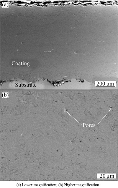
Fig. 1 Cross-sectional morphologies of sprayed FeCrSiBMn coating
3.2 Corrosion behavior
3.2.1 Potentiodynamic polarization curves
Figure 2 shows the potentiodynamic polarization curves of the FeCrSiBMn coating (a) and hard chromium coating (b) after immersion for 1, 14 and 28 d, respectively. During the immersion, each curve of FeCrSiBMn coating shows a spontaneous passivation with a wide passive region larger than 1.0 V (SCE) and relatively low passive current density in the order of magnitude about 10-5 A/cm2. However, the hard chromium coating exhibits a narrow passive region about 0.3 V (SCE) and relatively high passive current density of about 10-3 A/cm2. This means that FeCrSiBMn coating shows superior passive film protection ability to the hard chromium coating. For FeCrSiBMn and hard chromium coating, their transpassive potentials are about 1.0 V, implying similar resistance to localized corrosion in 3.5 % NaCl solution.
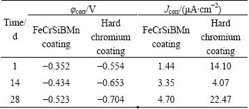
Table 1 lists the values of corrosion potential (ҰХcorr) and corrosion current density (Jcorr) obtained by the method of the Tafel extrapolation from Fig. 2. The ҰХcorr of the FeCrSiBMn coating decreased from -0.352 V to -0.523 V from 1 to 28 d, and the corresponding Jcorr increased with increasing the immersion time from 1.44 to 4.70 ҰМA/cm2 with extending the immersion time from 1 to 28 d, indicating that the corrosion resistance degraded gradually. The tendency for the hard chromium coating, however, is quite different. Although the ҰХcorr decreased from -0.554 V to -0.704 V gradually, the Jcorr of 4.07 ҰМA/cm2 was the lowest during 14 d immersion due to the corrosion products accumulated in the pores and cracks of the hard chromium coating. Then, with the dissolution of the corrosion products, the Jcorr increased to 22.47 ҰМA/cm2 with extending the immersion time to 28 d.
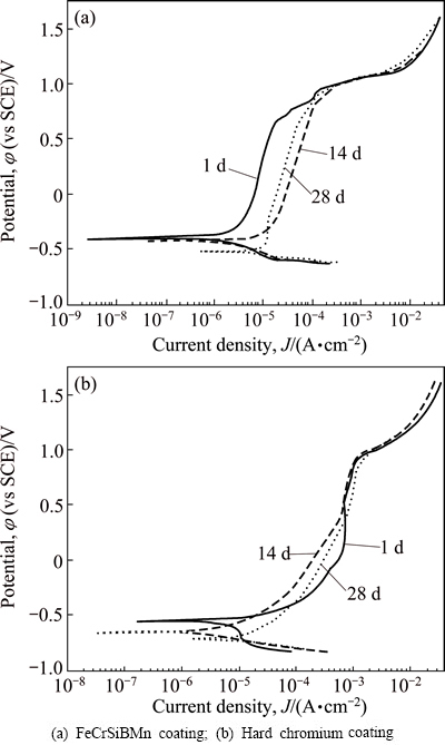
Fig. 2 Potentiodynamic polarization curves of samples in 3.5% NaCl solution
Table 1 Summary of electrochemical parameters of samples from potentiodynamic polarization curves
The corrosion resistance of the coatings is significantly sensitive to their structures and compositions [27]. Figure 3 shows the surface morphologies of the hard chromium coating. The typical cracks were obviously seen in Fig. 3(b), while the FeCrSiBMn coating exhibited a dense structure (Figs. 1(a) and (b)). The superior corrosion resistance of the FeCrSiBMn coating could be attributed to its dense structure and Cr element. Firstly, the low porosity and amorphous/nanocrystalline phase formed the dense structure of the FeCrSiBMn coating by HVOF technology at a rapid cooling rate. Thus, the aggressive penetration of the solution into the coating became very difficult and consequently the resistance to charge transfer was improved [28]. On the other hand, the Cr element dissolved quickly and formed a passive film in the solution, which acted as a barrier for anodic dissolution [29].
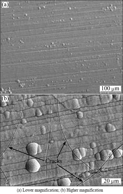
Fig. 3 Morphologies of surface of hard chromium coating
3.2.2 EIS plots
In order to evaluate the variation in the electrochemical reactions of the FeCrSiBMn coating and the hard chromium coating as a function of the immersion time, EIS was measured at various immersion time from 1 up to 28 d. Figures 4(a) and (b) show the Nyquist and Bode phase plots of the FeCrSiBMn coating in 3.5% NaCl solution at open-circuit potential (OCP), respectively. After immersion of 1 d, only a large capacitive loop was observed on Nyqusit plot (Fig. 4(a)) and one inflection point on corresponding Bode phase plot (Fig. 4(b)), indicating a single time constant for the FeCrSiBMn coating. This behavior could be attributed to the spontaneous passivation of the FeCrSiBMn coating in NaCl solution and the formation of the dense passive film. With increasing the immersion time from 7 to 28 d, the style of the Nyquist and Bode phase plots was changed. There were two capacitive loops on Nyquist plots (Fig. 4(a)). Correspondingly, the system showed two time constants according to the two inflection points on the Bode phase plots (Fig. 4(b)). The high frequency loop could be physically related to the coating defects, while the low frequency loop related to the corrosion process [30]. This could be due to the interfacial reactions between the coating and the substrate [18,24].
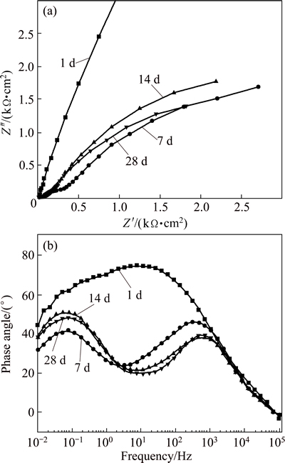
Fig. 4 Nyquist plots (a) and Bode phase plots (b) of FeCrSiBMn coating
Figures 5(a) and (b) show the Nyquist plots and Bode phase diagrams of the hard chromium coating after immersion for 1 to 28 d. Two capacitive loops were observed on the Nyquist plots (Fig. 5(a)), and correspondingly two inflection points appeared on the Bode phase plots (Fig. 5(b)), indicating that the hard chromium coating has two time constants. The Nyquist plots kept almost the same after immersion from 1 to 14 d, but a straight line with a slope of roughly 45Ўг appeared at the low frequency after immersion for 28 d, suggesting that Warburg impedance occurred when charge transfer was influenced by a semi-infinite length diffusion process [31,32].
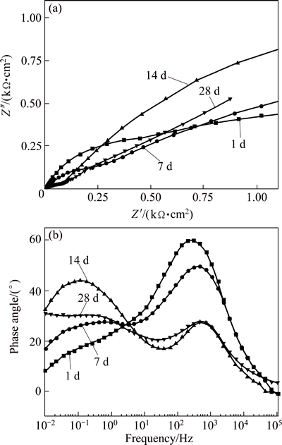
Fig. 5 Nyquist plots (a) and Bode phase plots (b) of hard chromium coating
Based on the above analysis, the equivalent circuits describing the electrochemical reaction for the FeCrSiBMn coating and the hard chromium coating are shown in Fig. 6. A constant phase element (Q) is commonly used to replace capacitance, because it has hardly a pure capacitance in a real electrochemical process [26]. The equivalent circuit for Fig. 6(a) consists of the resistance of the solution (Rs), the resistance of the coating (Rc), and the capacitance of the coating (Qc). For the equivalent circuit of Fig. 6(b), a pair of elements in parallel, namely, Qc and Rp (pore resistance), represent the dielectric properties of the coating. Another pair of Qdl (capacitance of the double layer) and Rct (charge transfer resistance at the coating/substrate interface) in parallel are adopted to describe the electrochemical reaction process at the coating/substrate interface. The equivalent circuit of Fig. 6(c) consists of an additional element Warburg impedance (Zw), a parameter containing diffusion coefficient and characteristic of stagnant layer. The equivalent circuits in Figs. 6(a) and (b) are used to fit the Nyquist plots of the FeCrSiBMn coating, while in Figs. 6(b) and (c) fit for the hard chromium coating. Similar equivalent circuits have been proposed by other researchers [25,30-32].
Tables 2 and 3 summarize the corrosion parameters extracted from the fitting equivalent circuit (Fig. 6). After immersion of 1 d, the FeCrSiBMn coating shows a very high Rc value of ~105 ҰёЎӨcm2 due to the formation of the compact passive film on the coating surface, which blocks the attack of the chloride ions. The protection of the passive film on the surface of the FeCrSiBMn coating is deteriorated after the immersion time of 7 d. Then, the aggressive solution penetrates into the coating via the pores and cracks. The Rp values decrease gradually from 123.9 to 57.75 ҰёЎӨcm2 with increasing the immersion time from 7 to 28 d, which is probably due to the increase of pores and pinholes inside the coating. The Rct values increase from 2350 to 3323 ҰёЎӨcm2 with increasing the immersion time from 7 to 14 d, and then decrease to 2826 ҰёЎӨcm2 with further increasing the immersion time to 28 d. This phenomenon is probably caused by the so-called Ў°plugging effectЎұ due to the local accumulation of corrosion products [32-34]. With increasing the immersion time to 28 d, the corrosion products are dissolved and the Rct values decrease, thus accelerating the penetration of the aggressive solution into the coating.
The corrosion behavior of the hard chromium coating is quite different from FeCrSiBMn coating. The chloride ions penetrate into the coating easily after the immersion time of 1 d due to the inherent defects such as small pores and micro-cracks inside the hard chromium coating. The Rp values decrease from 217.5 to 34.27 ҰёЎӨcm2 with increasing the immersion time from 1 to 14 d, indicating that the pores and cracks in the coating increase gradually. The Rp values increase to 58.91 ҰёЎӨcm2 with increasing the immersion to 28 d. This could also be attributed to the local accumulation of the corrosion products in the coating, which restrict the ion mass transfer between the active zones and aggressive solution via the coating defects. The Rct values decrease after immersion of 7 d, and then increase after immersion of 14 d. The increase of Rct values is probably due to the corrosion products accumulated in the interface of the hard chromium coating and the substrate. The Rct value decreases with further increasing the immersion time to 28 d, indicating that the corrosion process is dominated by diffusion of the electrolyte.
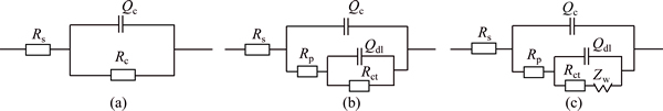
Fig. 6 Equivalent circuit representative of FeCrSiBMn coating (a, b) and hard chromium coating (b, c)
Table 2 Electrochemical parameters obtained from EIS spectra of FeCrSiBMn coating
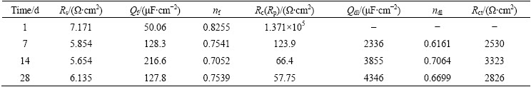
Table 3 Electrochemical parameters obtained from EIS spectra of hard chromium coating
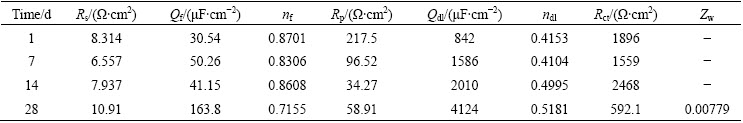
Due to the higher corrosion resistance of the FeCrSiBMn coating, the Rp and Rct values after a long-term immersion up to 28 d are much higher than those of the hard chromium coating. This can be explained from the differences in the microstructures. It is known that the permeable defects in coatings are beneficial for the corrosion by providing paths for the aggressive electrolyte to reach the steel substrate. The reason that the FeCrSiBMn coating holds better corrosion resistance can be attributed to the dense structure with little pores and partially corrosion resistant amorphous structure.
3.2.3 Morphology of corroded surface
Figure 7 presents the surface morphologies of FeCrSiBMn coating and hard chromium coating after immersion in a 3.5% NaCl solution for 28 d. For the FeCrSiBMn coating, only very few and small pores that sparely distributed on the surface were observed in Fig. 7(a), validating good corrosion resistance of the FeCrSiBMn coating. However, severe corrosion damage occurred in the hard chromium coating with big pores and corrosion pits as shown in Fig. 7(b). This was in consistence with the results of electrochemical tests.
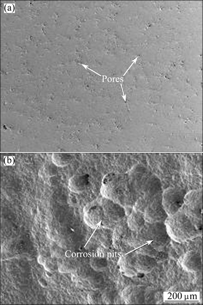
Fig. 7 Morphologies of surface of FeCrSiBMn coating (a) and hard chromium coating (b) after immersion in 3.5% NaCl solutions for 28 d
4 Conclusions
1) The potentiodynamic polarization tests indicate that compared to the hard chromium coating, the FeCrSiBMn coating exhibits a higher corrosion potential and a lower corrosion current density respectively. The FeCrSiBMn amorphous/nanocrystalline coating exhibits a wide passive region of about 1.0 V (SCE) and much lower passive current density than the hard chromium coating.
2) The EIS measurements show that the Rp and Rct values of the FeCrSiBMn coating are higher than those of the hard chromium coating. The corrosion performance of the FeCrSiBMn coating increases after immersion of 14 d due to the plugging of the corrosion products which hinders further attack.
3) After immersion in a 3.5 % NaCl solutions for 28 d, big pores and corrosion pits pile up in the hard chromium coating, while only small pores are observed in the FeCrSiBMn coating, validating the superior corrosion resistance of the latter.
References
[1] Espallargas N, Berget J, Guilemany J M, Benedetti A V, Suegama P H. Cr3C2-NiCr and WC-Ni thermal spray coatings as alternatives to hard chromium for erosionЁCcorrosion resistance [J]. Surf Coat Technol, 2008, 202: 1405-1417.
[2] Arun K, Venkatesha C. Experimental investigations on fracture toughness and transition temperature in hard chrome coated structural materials [J]. J Mater Process Technol, 2008, 207: 336-342.
[3] Guilemany J M, Espallargas N, FernЁўndez J, Suegama P H, Benedetti A V. High-velocity oxyfuel Cr3C2-NiCr replacing hard chromium coatings [J]. J Therm Spray Technol, 2005, 14: 335-341.
[4] Guilemany J M, Espallargas N, Suegama P H, Benedetti A V. Comparative study of Cr3C2-NiCr coatings obtained by HVOF and hard chromium coatings [J]. Corros Sci, 2006, 48: 2998-3013.
[5] Picas J A, Forn A,  G. HVOF coatings as an alternative to hard chrome for pistons and valves [J]. Wear, 2006, 261: 477-484.
[6] Pang S J, Zhang T, Asami K, Inoue A. Synthesis of FeЁCCrЁCMoЁCCЁCBЁCP bulk metallic glasses with high corrosion resistance [J]. Acta Mater, 2002, 50: 489-497.
[7] Farmer J C, Haslam J J, Day S D, Lian T, Saw C, Hailey P, Choi J, Rebak R, Yang N, Payer J. Corrosion resistance of thermally sprayed high-boron iron-based amorphous-metal coatings: Fe49.7Cr17.7Mn1.9Mo7.4W1.6B15.2C3.8Si2.4 [J]. J Mater Res, 2007, 22: 2297-2311.
[8] Hazra S, Sabiruddin K, Bandyopadhyay P P. Plasma and HVOF sprayed WC-Co coatings as hard chrome replacement solution [J]. Surf Eng, 2012, 28: 37-43.
[9] Wu Y P, Lin P Y, Chu C L, Wang Z H, Cao M, Hu J H. Cavitation erosion characteristics of a FeЁCCrЁCSiЁCBЁCMn coating fabricated by high velocity oxy-fuel(HVOF) thermal spray [J]. Mater Lett, 2007, 61: 1867-1872.
[10] Zhou Z, Wang L, Wang F C, Zhang H F, Liu Y B, Xu S H. Formation and corrosion behavior of Fe-based amorphous metallic coatings prepared by detonation gun spraying[J]. Surf Coat Technol, 2009, 204: 563-760.
[11] Liu X Q, Zheng Y G, Chang X C, Hou W L, Wang J Q, Tang Z, Burgess A. Microstructure and properties of Fe-based amorphous metallic coating produced by high velocity axial plasma spraying [J]. J Alloys Compd, 2009, 484: 300-307.
[12] Wang Li-jun, Qiu Pei-xian, Liu Yan, Zhou Wu-xi, Gou Guo-ping, Chen Hui. Corrosion behavior of thermal sprayed WC cermet coatings containing metallic binders in saline environment [J]. Transactions Nonferrous Metals Society of China, 2013, 23(9): 2611-2617.
[13] Ma Jing, Yan Dong-qing, Hu Jian-wen, Zhang Xin, Li Yang. Reactive HVOF sprayed TiN-matrix composite coating and its corrosion and wear resistance properties [J]. Transactions Nonferrous Metals Society of China, 2013, 23(4): 1011-1018.
[14] Han M S, Lee S J, Kim M S, JANG S K, KIM S J. Electrochemical characteristics of HVOF spray coated layer with WC-27NiCr and WC-10Co4Cr for Al bronze [J]. Transactions Nonferrous Metals Society of China, 2012, 22(S3): s753-s759.
[15] Wang Shan-lin, Cheng Jing-chang, YI Seong-hoon, KE Li-ming. Corrosion resistance of Fe-based amorphous metallic matrix coating fabricated by HVOF thermal spraying [J]. Transactions Nonferrous Metals Society of China, 2014, 24(1): 146-151.
[16] Hong S, Wu Y P, Gao W W, Wang B, Guo W M, Lin J R. Microstructural characterisation and microhardness distribution of HVOF sprayed WC-10Co-4Cr coating [J]. Surf Eng, 2014, 30: 53-58.
[17] Bakare M s, Voisey K T, Chokethawai K, McCartney D G. Corrosion behavior of crystalline and amorphous forms of the glass forming alloy Fe43Cr16Mo16C15B10 [J]. J Alloys Compd, 2012, 527: 210-218.
[18] Yang Y, Zhang C, Peng Y, Yu Y, Liu L. Effects of crystallization on the corrosion resistance of Fe-based amorphous coatings [J]. Corros Sci, 2012, 59: 10-19.
[19] Zhang C, Guo R Q, Yang Y, Wu Y, Liu L. Influence of the size of spraying powders on the microstructure and corrosion resistance of Fe-based amorphous coating [J]. Electrochem Acta, 2011, 56: 6380-6388.
[20] Wang Y, Zheng Y G, Ke W, Sun W, Wang J. Corrosion of high-velocity oxy-fuel (HVOF) sprayed iron-based amorphous metallic coatings for marine pump in sodium chloride solutions [J]. Mater Corros, 2012, 63: 685-694.
[21] Wang Y, Jiang S, Zheng Y G, Ke W, Sun W, Chang X. Effect of processing parameters on the microstructures and corrosion behavior of HVOF sprayed Fe-based amorphous metallic coatings [J]. Mater Corros, 2013, 64: 1-10.
[22] Wu Y P, Lin P H, Wang Z H, Li G Y. Microstructure and microhardness characterization of a Fe-based coating deposited by high-velocity oxy-fuel thermal spraying [J]. J Alloys Compd, 2009, 481: 719-724.
[23] Wu Y P, Lin P H, Xie G Z, Hu J H, Cao M. Formation of amorphous and nanocrystalline phases in high velocity oxy-fuel thermally sprayed a FeЁCCrЁCSiЁCBЁCMn alloy [J]. Mater Sci Eng A, 2006, 430: 34-39.
[24] Guo R Q, Zhang C, Yang Y, Peng Y, Liu L. Corrosion and wear resistance of a Fe-based amorphous coating in underground environment [J]. Intermetallics, 2012, 30: 94-99.
[25] Wang Y, Jiang S, Zheng Y G, Ke W, Sun W, Wang J. Effect of porosity sealing treatments on the corrosion resistance of high-velocity oxy-fuel (HVOF)-sprayed Fe-based amorphous metallic coatings [J]. Surf Coat Technol, 2011, 206: 1307-1318.
[26] Qin Y J, Wu Y P, Zheng Y G, Hong S, Guo J. Corrosion behavior of FeCrSiB alloy coatings prepared by HVOF thermal spraying [J]. Trans China Weld Inst, 2014, 35: 104-107. (in Chinese)
[27] Li R F, Li Z G, Zhu Y Y, Qi K. Structure and corrosion resistance properties of NiЁCFeЁCBЁCSiЁCNb amorphous composite coatings fabricated by laser processing [J]. J Alloys Compd, 2013, 580: 327-331.
[28] Wang L, Chao Y S. Corrosion behavior of Fe41Co7Cr15Mo14C15- B6Y2 bulk metallic glass in NaCl solution [J]. Mater Lett, 2012, 69: 76-78.
[29] Yang D, Liu C, Liu X, Qi M, Lin G. EIS diagnosis on the corrosion behavior of TiN coated NiTi surgical alloy [J]. Curr Appl Phys, 2005, 5: 417-421.
[30] Liu Z, Dong Y C, Chu Z H, Yang Y, Li Y Z, Yan D R. Corrosion behavior of plasma sprayed ceramic and metallic coatings on carbon steel in simulated seawater [J]. Mater Des, 2013, 52: 630-637.
[31] Verdian M M, Raeissi K, Salehi M. Corrosion performance of HVOF and APS thermally sprayed NiTi intermetallic coatings in 3.5% NaCl solution [J]. Corros Sci, 2010, 52: 1052-1059.
[32] Verdian M M, Raeissi K, Salehi M. Electrochemical impedance spectroscopy of HVOF-sprayed NiTi intermetallic coatings deposited on AISI 1045 steel [J]. J Alloys Compd, 2010, 507: 42-46.
[33] Liu C, Bi Q, Matthews A. EIS comparison on corrosion performance of PVD TiN and CrN coated mild steel in 0.5 M NaCl aqueous solution [J]. Corros Sci, 2001, 43: 1953-1961.
[34] Wang Y, Jiang S L, Zheng Y G, Ke W, Sun W H, Wang J Q. Electrochemical behaviour of Fe-based metallic glasses in acidic and neutral solutions [J]. Corros Sci, 2012, 63: 159-173.
і¬ТфЛЩ»рСжЕзНҝFeCrSiBMn·Зҫ§/ДЙГЧҫ§НҝІгөДіӨЖЪёҜКҙРРОӘ
ЗШУсҪҝЈ¬ОвУсЖјЈ¬ХЕҪЁ·еЈ¬№щОДГфЈ¬әй кЙЈ¬іВАцСЮ
әУәЈҙуС§ БҰС§УлІДБПС§Фә ҪрКфІДБПУл·А»ӨСРҫҝЛщЈ¬ДПҫ© 210098
ХӘ ТӘЈәІЙУГі¬ТфЛЩ»рСж(HVOF)ЕзНҝјјКхЦЖұёFeCrSiBMn·Зҫ§ДЙГЧҫ§НҝІгЈ¬НҝІгәс¶ИОӘ700 ҰМmЈ¬ҝЧП¶ВКОӘ0.65%ЎЈАыУГ¶ҜөзО»ј«»ҜЗъПЯәНөз»ҜС§Чиҝ№ЖЧІвКФСРҫҝFeCrSiBMnНҝІгәН¶ФұИСщ¶ЖёхІгФЪ3.5%ИЬТәЦРөДіӨЖЪёҜКҙРРОӘЎЈҪб№ыұнГчЈ¬Ул¶ЖёхІгПаұИЈ¬FeCrSiBMnНҝІгҫЯУРҪПёЯөДёҜКҙөзО»әНҪПөНөДёҜКҙөзБчГЬ¶ИЎЈFeCrSiBMnНҝІгөДҝЧП¶өзЧи(Rp)әНөзәЙЧӘТЖөзЧи(Rct)ұИ¶ЖёхІгөДёЯЎЈҙЛНвЈ¬ФЪNaClИЬТәЦРҪюЕЭ28 dәуЈ¬FeCrSiBMnНҝІгұнГжҪц№ЫІмөҪОўРЎөДҝЧП¶ЎЈFeCrSiBMnНҝІгУл¶ЖёхІгПаұИҫЯУРУЕТмөДДНёҜКҙРФДЬЎЈХвЦчТӘУлFeCrSiBMnНҝІгЦВГЬөДҪб№№Ј¬ҪПөНөДҝЧП¶ВКј°·Зҫ§ПаөДҙжФЪУР№ШЎЈ
№ШјьҙКЈәі¬ТфЛЩ»рСжЕзНҝЈ»НҝІгЈ»Fe»щ·Зҫ§/ДЙГЧҫ§Ј»ДНёҜКҙРФДЬ
(Edited by Yun-bin HE)
Corresponding author: Yu-ping WU; Tel: +86-25-83787233; Fax: +86-25-83787233; E-mails: wuyuping@hhu.edu.cn, wuyphhu@163.com
DOI: 10.1016/S1003-6326(15)63709-8

