п���ε�ظ�����̼������������п���ϵ�����ǰ�����̼���Ʊ�������
��Դ�ڿ����й���ɫ����ѧ��(Ӣ�İ�)2019���10��
�������ߣ����� ��־�� ����� � ������ ������
����ҳ�룺2151 - 2159
�ؼ��ʣ�̼��������ZnO���ܽ�-����������ײ�״�ṹ��п-�����
Key words��carbon-coated nano-ZnO; sol-gel method; porous hierarchical architecture; Zn-Ni battery
ժ Ҫ����Լ��Զ���п��ظ�����������̼�����������ϵ͵IJ��㣬����һ���ȴ�������ǰ�����Ʊ�п������̼��������ZnO (nano-ZnO@C)���ϣ��о����۽ṹ��绯ѧ���ܡ��������������ZnO��nano-ZnO@C�����ֲ�ṹ����ԭʼ�����ߴ�Լ100 nm���������ҵ����п�����Ʊ���ZnO���ԣ�nano-ZnO@C��Ϊп����ʱ���и��ߵĵ绯ѧ���ԡ����͵�������õ�ѭ���ȶ��ԣ��ŵ�������ɴ�622 mA��h/g������Ҫԭ������̼��������ZnO������ά�ָ����������ʸ������ʵ�ͬʱ��������п֦����������缫�����ܻ���
Abstract: Although carbon coating can improve the cycle life of anode for alkaline Zn batteries, the specific capacity reported is still lower compared with nanosized ZnO. Herein, carbon-coated nanosized ZnO (nano-ZnO@C) was synthesized by one-step heat treatment from a gel precursor in N2. Commercial ZnO and homemade ZnO prepared similarly in air atmosphere were studied for comparison. Structure analysis displayed that both nano-ZnO@C and homemade ZnO had a porous hierarchical agglomerated architecture produced from primary nanoparticles with a diameter of approximately 100 nm as building blocks. Electrochemical performance measurements showed that nano-ZnO@C displayed the highest electrochemical activity, the lowest electrode resistance, the highest discharge capacity (622 mA��h/g), and the best cyclic stability. These properties were due to the combination of nanosized ZnO and the physical capping of carbon, which maintained the high utilization efficiency of nano-ZnO, and simultaneously prevented dendrite growth and densification of the anode.
Trans. Nonferrous Met. Soc. China 29(2019) 2151-2159
Ke PENG, Zhi-jian ZHANG, Ze-jun ZHAO, Chao YANG, Zhong-liang TIAN, Yan-qing LAI
School of Metallurgy and Environment, Central South University, Changsha 410083, China
Received 15 November 2018; accepted 16 August 2019
Abstract: Although carbon coating can improve the cycle life of anode for alkaline Zn batteries, the specific capacity reported is still lower compared with nanosized ZnO. Herein, carbon-coated nanosized ZnO (nano-ZnO@C) was synthesized by one-step heat treatment from a gel precursor in N2. Commercial ZnO and homemade ZnO prepared similarly in air atmosphere were studied for comparison. Structure analysis displayed that both nano-ZnO@C and homemade ZnO had a porous hierarchical agglomerated architecture produced from primary nanoparticles with a diameter of approximately 100 nm as building blocks. Electrochemical performance measurements showed that nano-ZnO@C displayed the highest electrochemical activity, the lowest electrode resistance, the highest discharge capacity (622 mA��h/g), and the best cyclic stability. These properties were due to the combination of nanosized ZnO and the physical capping of carbon, which maintained the high utilization efficiency of nano-ZnO, and simultaneously prevented dendrite growth and densification of the anode.
Key words: carbon-coated nano-ZnO; sol-gel method; porous hierarchical architecture; Zn-Ni battery
1 Introduction
Pollution-free electrode materials and electrolytes have been proposed for next-generation energy-storage devices [1-4]. With nontoxic metal Zn as anodic material and alkaline solution as electrolytes, green secondary Zn batteries have continually been received worldwide attention. Moreover, metal Zn with advantages of high specific energy, low equilibrium potential, high specific power and low-cost makes secondary alkaline Zn batteries competitive as candidates to lithium ion battery [5,6]. However, the Zn electrode has problems of formation of Zn dendrite and shape change which is mainly rooted in the solubility of ZnO and redistribution of active substances, resulting in the rapid capacity fading of secondary alkaline Zn batteries [7,8]. To improve the battery cycle performance, many efforts have been made, such as adding additives in electrolyte [9,10], and surface coating on ZnO particles [11,12]. Among these methods, surface coating has attracted researchers�� attention in recent years due to its better electrochemical performance and stable discharge capacity.
As an economic and feasible surface coating technology, carbon coating can provide protection layer to reduce ZnO dissolution and improve conductivity to reduce interface impedance [13]. Although previous works including hydrothermal synthesis [14], ball milling [15] and chemical polymerization [16], have remarkably enhanced the cycle performance of anode, the discharge capacities of ZnO electrodes remain low (��500 mA��h/g) because commercial ZnO is used as raw material. Given their size and special morphology, nanosized ZnO (nano-ZnO) has higher discharge capacity and electrochemistry activity than commercial ZnO [17-19]. However, it still has the problem of dissolution. Previous researches only focused on the carbon coating or nanoscale separately. Therefore, considering both of them together is anticipated to further enhance the performance of Zn anode. On account of the high surface free energy, nano-ZnO tends to agglomerate in the preparation process, prone to cause uneven coating on nano-ZnO subsequently [20,21].
In this work, the carbon-coated nano-ZnO (nano-ZnO@C) has been synthesized by one-step heat treatment from a Zn(OH)2 gel precursor with surface modifier polyethylene glycol (mean relative molecular mass 400) as carbon source to achieve the uniform distribution of carbon and nano-ZnO. The microstructure and electrochemical properties of nano-ZnO@C were investigated.
2 Experimental
2.1 Material synthesis
Nano-ZnO@C was prepared by one-step heat treatment from a Zn(OH)2 gel precursor produced by complexing sol-gel method. Firstly, 2.5 mL of poly- ethylene glycol (PEG-400, mean relative molecular mass 400, AR) and 3.3 g of zinc acetate (Zn(CH3COO)2��2H2O, AR) were dissolved in 10 mL distilled water respectively and stirred with a magnetic stirrer to achieve a transparent solution. An amount of ammonia solution (25%-28%) was then added dropwise into the mixture to adjust the pH to ~10, and a milky solution was obtained. Next, 25 mL of ethanol was dropped into the solution under stirring, and the mixture was heated to 77 ��C. After 4 h of stirring at 77 ��C until completion of zinc acetate hydrolysis, another amount of ammonia solution was dripped into the solution as complexant until a transparent sol was obtained. The sol was dried at 80 ��C in vacuum oven overnight. Finally, the dried gel precursor was calcined at 600 ��C for 8 h in N2 atmosphere with a heating rate of 5 ��C/min to obtain nano-ZnO@C. Homemade ZnO was prepared with the same method except that the heat treatment was in air. The schematic illustration of the synthesis of samples is shown in Scheme 1. To measure the carbon content of nano-ZnO@C, a specific mass of sample was heated at 600 ��C for 3 h under air atmosphere. After the calcined samples were weighed out, the contents of carbon in nano-ZnO@C were calculated to be 6.59 wt.%.
2.2 Material characterization
The crystal structures of as-prepared samples were confirmed by powder X-ray diffractometry (XRD, Rigaku 3014) using Cu K�� radiation. The surface morphology and microstructure of the as-prepared samples were observed under the scanning electron microscope (SEM JSM-6360LV, JEOL) and the transmission electron microscope (TEM, Tecnai G2 20ST).
2.3 Preparation of Zn electrodes
The Zn electrodes were prepared by pasting mushy anode slurry on a copper mesh substrate (2.0 cm ��2.0 cm in size). The slurry was made by mixing 85% nano-ZnO@C material, 10% acetylene black and 5% polytetrafluoroethylene (PTFE, 60 wt.%, in diluted emulsion) with moderate deionized water thoroughly. Afterwards, the obtained Zn electrode was dried at 70 ��C in vacuum environment and pressed to a thickness of 0.3 mm with 128 mg active material per electrode. For comparison, the homemade ZnO electrode and commercial ZnO (Xilong Chemical Co., Ltd., AR) electrode were also prepared with similar method.
2.4 Measurement of electrochemical performance
The cyclic voltammetry (CV) and electrochemical impedance spectroscopy (EIS) tests were carried out in a conventional three-electrode system at room temperature using Hg/HgO as the reference electrode, a commercial sintered Ni(OH)2 electrode as the counter electrode and as-prepared zinc-pasted electrode as the working electrode. The electrolyte was 6 mol/L KOH solution saturated with ZnO. CV and EIS were performed on an electrochemical workstation (Solartron 1470E). The CV measurement was conducted with a scanning rate of 10 mV/s shifting from -0.9 to -1.65 V. The EIS measurement was performed in a frequency range between 0.1 Hz and 10 kHz, and the AC signal amplitude was ��10 mV.
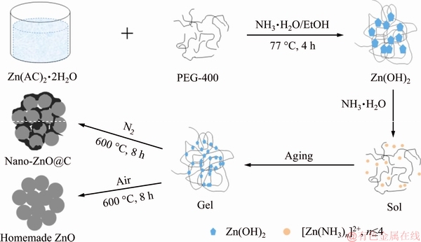
Scheme 1 Schematic illustration of synthesis of nano-ZnO@C and homemade ZnO
For galvanostatic charge/discharge cycle test, the simulated cells were charged at 0.2C for 5.5 h and discharged at 0.5C down to 1.2 V (cut-off). The cycle tests were performed on a battery-testing instrument (CT2001A, LAND) at room temperature. During the cycling processes, the testing cells were assembled by placing the commercial sintered Ni(OH)2 electrodes and zinc electrodes into a simple organic glass cell container. The positive electrode was the commercial sintered Ni(OH)2 with the capacity of four times as large as that of the zinc electrode, making full use of the active material in zinc electrode. The negative electrode was the zinc-pasted electrode. The electrolyte was a solution of 6 mol/L KOH saturated with ZnO, and a multilayer polypropylene microporous membrane as the separator.
3 Results and discussion
3.1 Material characterization
Figure 1 shows the XRD patterns of nano-ZnO@C sample and homemade ZnO sample. All the diffraction peaks of two samples are in good accordance with JPCDS card No. 89-1397, suggesting that the as-prepared samples contain ZnO with a hexagonal wurtzite structure. The corresponding peak height ratios and narrow sharp peaks indicate that the crystallinities of two samples are very high. Compared with that of the homemade nano-ZnO, the diffraction peak intensity of nano-ZnO@C is decreased slightly. The reason may be that carbon is amorphous when the calcination temperature is below 1000 ��C, which results in a decrease of peak intensity [22]. Accordingly, amorphous carbon is not detected in the XRD pattern of nano-ZnO@C [23].
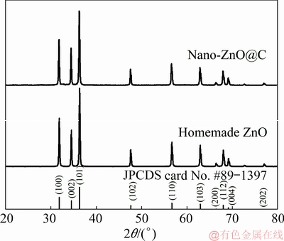
Fig. 1 XRD patterns of nano-ZnO@C and homemade ZnO samples
SEM analyses were conducted at different resolutions to investigate the morphology features of nano-ZnO@C and homemade ZnO. As shown in Fig. 2, the particle morphologies of homemade ZnO (Fig. 2(b)) and nano-ZnO@C (Fig. 2(c)) are totally different from that of commercial ZnO (Fig. 2(a)). The commercial ZnO particles present typical hexagonal prismatic shape, and the grain size distribution is very broad in the range of 200-800 nm, while the particles of nano-ZnO@C and homemade ZnO have the shape with an irregular morphology and show micron size. The size of homemade ZnO particles is approximately 15 ��m, whereas that of nano-ZnO@C particles is approximately 8 ��m. The SEM images of two samples with a higher amplification factor (Figs. 2(d) and (e)) show that both of them have a porous hierarchical architecture with primary nanoparticles as building blocks. The attachments of primary particles of homemade ZnO are compacted, but plenty of pores existed in the secondary particles. These pores run through the entire body of agglomerated particle and can provide the pathway for the diffusion of electrolyte. By contrast, the contact interface of primary particles in nano-ZnO@C is more well-defined than that in homemade ZnO. This is due to the control effect of relative molecule mass during carbonizing process, which prevents the direct connection of ZnO nanoparticles [24]. Thus, the large size of secondary particles of nano-ZnO@C and homemade ZnO should not worsen the high discharge capacity of nano-ZnO [25].
TEM observation was conducted to further confirm the situation of carbon coating over the surface of nano-ZnO@C. As shown Fig. 3(a), nano-ZnO primary particles with the size of approximately 100 nm are connected together by carbon. The carbon has not fully filled the interstitial region between primary nano- particles. This feature can also be observed in Fig. 2(e), which indicates that the carbon in nano-ZnO@C will not hinder the penetration of electrolyte into the inside of particles and a high discharge capacity should be allowed to nano-ZnO@C similar to homemade ZnO. Meanwhile, the carbon forms successive electronic conductive networks, which can make the drainage of electron in ZnO electrode easy. The selected-area electron diffraction suggests that the carbon (Fig. 3(b)) in interstitial region is amorphous (inset in Fig. 3(b)). This result is consistent with the XRD pattern above.
3.2 Electrochemical analysis
To investigate the electrochemical behaviors of commercial ZnO and as-prepared samples in alkaline electrolyte, CV tests were performed in 6 mol/L KOH aqueous solution saturated with ZnO after discharging at the fifth cycle measurement. As shown in Fig. 4, the cathode current increasing along with the decrease of potential corresponds to the reduction of ZnO. The cathodic peaks of commercial ZnO electrode (curve A), homemade ZnO (curve B) and nano-ZnO@C (curve C) appeared at -1.563, -1.572 and -1.555 V, respectively. Compared with that of electrode A, the cathode peaks of electrodes B and C show higher cathode current and larger cathode area. These results indicate that nano-ZnO has rapid reduction reaction kinetics, and the charging process is rapid and efficient. When the cathode scan further proceeds to more negative potential, the current of electrode C still decreases, whereas the currents of electrodes A and B increase again and the transformation point of electrode B is more negative than that of electrode A. This result can be attributed to the hydrogen evolution, which remains the primary reaction after the transformation point [26]. That is, the homemade ZnO has higher hydrogen evolution overpotential and it is further enhanced by carbon coating. When the potential scan is switched to the positive direction, the anode peaks of electrodes A, B and C appeared at -1.251, -1.220 and -1.222 V after the cathode current drops to 0 A. When the positive shift of potential continues, anodic current apparently decreases, which presents the passivation process of Zn. The anode peaks of electrodes B and C are also higher and larger than that of commercial ZnO, and the anode peak of electrode C is the highest and largest. These results can be attributed to the high electrochemical activity of nano-ZnO, and carbon coating executes further enhancement of electrochemical performance of nano-ZnO [18]. The larger the anodic peak area is, the more the discharge capacity of the anode will possess. Thus, the discharge capacity of nano-ZnO@C electrode should be further enhanced. Besides, the higher polarization of electrodes B and C may be due to the agglomerated structure that both homemade ZnO and nano-ZnO@C possess.
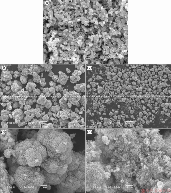
Fig. 2 SEM image of commercial ZnO (a), low-resolution (b, c) and high-resolution (d, e) SEM images of homemade ZnO (b, d) and nano-ZnO@C (c, e) samples
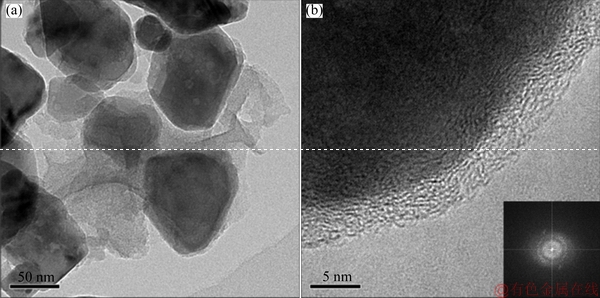
Fig. 3 TEM images of nano-ZnO@C sample at low-resolution (a) and high-resolution (b) and electron diffraction pattern of carbon (inset in (b))

Fig. 4 Cyclic voltammogram curves of commercial ZnO (curve A), homemade ZnO (curve B) and nano-ZnO@C (curve C) samples

Fig. 5 Nyquist plots for commercial ZnO, homemade ZnO and nano-ZnO@C samples
EIS analyses were performed to investigate the impedance of different Zn electrodes. Figure 5 shows the corresponding Nyquist plots and fitting equivalent circuit. As observed from Fig. 5, each plot is composed of a capacitive semicircle arc in high frequency and a straight line in low frequency. The high-frequency semicircle arc corresponds to the charge-transfer resistance (Rct) in parallel with the double-layer capacitance (CPE), and the low-frequency straight line corresponds to the Warburg impedance (Zw), which represents the diffusion of zincate in zinc electrode. The equivalent circuit shown in Fig. 5 is used to fit the electrochemistry impedance spectra in which Rs is ohmic resistance, involving the resistance of current collector, electrode material and electrolyte, CPE represents the constant-phase element related to the double-layer capacitance, the charge-transfer resistance Rct and Warburg impedance Zw reflect the diffusion capacity of zincate in zinc electrode. Table 1 lists the parameters calculated based on impedance diagram equivalent circuit using different electrodes. The commercial ZnO shows the maximum charge-transfer resistance value (3.516 ����cm2), whereas nano-ZnO@C shows the minimum charge-transfer resistance value (2.154 ����cm2), and the value of homemade ZnO is in-between (3.371 ����cm2). A smaller Rct usually means easier electrochemical reaction and faster kinetics process in charge-transfer process of electrode material. The less decreased Rct of homemade ZnO compared with commercial ZnO is due to the high electrochemical activity of nano-ZnO, and a further decreased Rct of nano-ZnO@C should be the reason of carbon layers on the surface of particles, which enable easier electrochemical reaction [15]. However, due to the high specific area and large surface energy of nanosized particle, nano-ZnO precursor particles tend to agglomerate during heat treating process. Moreover, the interfacial resistance would be obviously higher due to the increased particle/particle boundary [27]. Thus, the homemade ZnO has the largest Rs (0.594 ����cm2). But the ohmic resistance is decreased in nano-ZnO@C. This is attributed to the conductive network formed by amorphous carbon, which benefits the flow of charges within active materials. Both ohmic resistance and charge-transfer resistance indicate that nano-ZnO@C electrode should have the least polarization among the three samples. However, the cyclic voltammetry curves show that commercial ZnO has the least electrode polarization and that of nano-ZnO@C decreases just a little compared with that of homemade ZnO. This is because the electrolyte has a greater diffusion resistance into the inside of particles composed of primary ZnO nanoparticles, which have a low porosity than commercial ZnO electrode.
Table 1 EIS parameters of zinc electrodes in 6 mol/L KOH saturated with ZnO

Figure 6(a) presents the variations of specific discharge capacity with cycle number for different zinc electrodes at 0.2C rate in alkaline electrolyte. As observed from Fig. 6(a), the commercial ZnO anode has an initial discharge capacity of 414.5 mA��h/g and its activated discharge capacity of 541 mA��h/g is at the fourth cycle, whereas the homemade ZnO anode shows a higher initial discharge capacity of 567.3 mA��h/g and requires only two cycles to achieve activation with a discharge capacity of 604 mA��h/g. This sufficiently indicates the advantage of nano-ZnO in discharge capacity compared with commercial ZnO, although the particles have an agglomerated structure. Previous studies showed that the passivation of ZnO will occur when an excessive concentration of hydroxide or salt achieves in the electrolyte close to the surface of zinc particle [28]. At the first stage, a porous and white layer is formed by the saturated zincate, which allows the electrolyte transmission. When porous layer reaches a certain thickness, a light gray and dense layer will be formed upon the interface between the zinc and outer porous layer [29,30]. It acts as a diffusion barrier to OH- ion and H2O and the discharge voltage of batteries drops rapidly. Then, the passivation of zinc electrode occurs. As illustrated in Fig. 6(b), compared with commercial ZnO, nano-ZnO particles have higher capacity under the same passivation thickness due to their size. The discharge product in the region marked with red dash line can be responsible for the additional discharge capacity of nano-ZnO. For nano-ZnO@C anode, the initial discharge capacity is the lowest and it takes six cycles to accomplish activation with the highest capacity of 622 mA��h/g, even higher than that of the homemade ZnO anode. This result can be explained by the carbon layer, which coats the nano-ZnO particles and connects them together. On the one hand, the carbon layer acts as a barrier layer to the penetration of electrolyte in the activation process. Thus, the activation process is longer than that of commercial ZnO. On the other hand, with a higher electrical conductivity than that of semiconductor ZnO, the carbon acts as a conducting medium on the surface of particles to increase the utilization efficiency of active materials. Anyway, with the cycle proceeding, the discharge capacities of homemade ZnO anode and commercial ZnO anode decay apparently compared with that of the nano-ZnO@C anode. After the 50th cycling, the discharge capacity of nano-ZnO@C anode remains 72.4%, whereas the retention rates of discharge capacity for commercial ZnO and homemade ZnO are at 60.4% and 39.6%, separately. This result can be traced to the dissolution of ZnO in electrolyte, which brings out Zn dendrites and shape change for Zn electrode, both resulting in an irreversible loss of capacity of battery [31,32]. Except for the highest discharge capacity being inherited from nano-ZnO, the nano-ZnO@C anode persistently showed an improved cycling ability. Two effects, capping of carbon and uniform current distribution, are responsible to good cycle performance of nano-ZnO@C material. Spatially physical capping of carbon protects ZnO particle against the dissolution from alkali liquor, and the improved current distribution retards the dendrite growth which is usually facilitated by high local current. Thus, as an adverse result caused by shape change and dendrites, the capacity fading is restricted, and a further enhancement of discharge capacity with a stable cycle performance can be realized based on nano-ZnO.
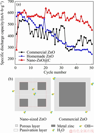
Fig. 6 Variations of specific discharge capacity with cycle numbers of commercial ZnO, homemade ZnO and nano-ZnO@C (a), and schematics of discharge capacity difference in nano-ZnO@C particles and commercial ZnO particles (b)
Figure 7 displays the typical charge-discharge curves of Zn/Ni cells assembled for the three different anode materials tested at the sixth cycle. As shown in Fig. 7, the charge voltages of anodes B and C are higher than that of anode A in the earlier stage of charge process. This result matches well with the cyclic voltammetry curves as well as the discharge voltage in the earlier stage of discharge process. However, the result of AC impedance spectra shows that the nano-ZnO@C has the lowest ohmic resistance and charge-transfer resistance, which indicates that the polarization of nano-ZnO@C anode should have a lower polarized voltage drop. The phenomenon may be due to the agglomerated structures of homemade ZnO and nano-ZnO@C. As the electrode reaction runs, the bulk solution should meet the requirements of the consumption of OH- ion and H2O on reaction interface by supplying the reactant to pass through the interspace in agglomerates. The insufficient pores in agglomerates make the lacking of OH- ion and H2O for the reaction and lead to a totally high-polarized voltage drop. Besides, anode C shows a lower charge voltage plateau and a higher discharge voltage plateau than anode B. The reason is that the carbon coating can apparently provide sufficient electrical contact between particles and reduce the resistance of reaction process.

Fig. 7 Typical charge�Cdischarge curves of commercial ZnO (curve A), homemade ZnO (curve B) and nano-ZnO@C (curve C) tested at the 6th cycle

Fig. 8 Charge�Cdischarge curves of homemade ZnO (a) and nano-ZnO@C (b) at the 10th, 30th and 50th cycles, and schematic showing densification of homemade ZnO with porous hierarchical agglomerated structure (c)
To investigate the differences of the polarized variation between homemade ZnO electrode and nano-ZnO@C electrode, charge-discharge curves at different cycles were analyzed. As shown in Figs. 8(a) and (b), with cycle the proceeding, the charge voltage plateaus rise and the discharge voltage plateaus drop rapidly, which indicate that the polarization of electrode gradually increases. Meanwhile, as a negative phenomenon of the polarization in cells, charge voltage fluctuation derived from the inner short circuit caused by the dendritic penetration through separator also appeared at both assembled batteries. Compared with nano- ZnO@C, the short circuit of battery with homemade ZnO as anode material occurred at the 10th cycle and accompanied the subsequent cycles. For nano-ZnO@C, the tolerance of dendrites was completely increased by carbon coating. The mechanism description can be explained by Fig. 8(c). At the first stage, the porous hierarchical agglomerated structure of homemade ZnO allows the penetration of electrolyte, and the higher discharge capacity of nano-ZnO can be provided. However, the nano-ZnO has great dissolution activity due to its larger specific surface area, and Zn/ZnO conversion reaction is a dissolution/redeposition process. The redisposition makes nanoparticles grow and further agglomerate together, which is known as densifying. Densifying reduces the reactive specific area of homemade ZnO and causes a shrinking porosity, both increasing the current density of particle surface. Thus, the polarization increases continually and the dendrites are inclined to be formed simultaneously. The consequent capacity fading occurs naturally. Due to the protection of carbon on the surface of nano-ZnO, the dissolution of nano-ZnO is slowed down and densifying and dendrite growth are prevented. The high active specific surface area and the porosity are maintained [15]. Thus, the cycle life of nano-ZnO@C electrode is improved.
4 Conclusions
(1) Nano-ZnO@C and homemade ZnO with porous hierarchical agglomerated architecture have been prepared by one-step heat treatment from a gel precursor separately.
(2) The nano-ZnO@C anode exhibited higher discharge capacity and more stable cycle performance as anode material compared with homemade ZnO, which with a same structure was not suitable for stable cycling in the secondary Zn/Ni rechargeable battery.
(3) The reason could be the good electronic conductivity and surface coating of carbon. Surface coating of carbon not only further enhanced the high discharge capacity originated from the nano-ZnO particles, but also decreased the electrode polarization and prevented densification and dendrite growth. Therefore, nano-ZnO@C is a potential anodic material with high discharge capacity and long service life for the secondary alkaline Zn batteries.
References
[1] XU C J, DU H D, LI B H, KANG F Y, ZENG Y Q. Capacitive behavior and charge storage mechanism of manganese dioxide in aqueous solution containing bivalent cations [J]. Journal of the Electrochemical Society, 2009, 156(1): A73-A78.
[2] XIAO C L, ZHANG S C, WANG S B, XING Y L, LIN R X, WEI X, WANG W X. ZnO nanoparticles encapsulated in a 3D hierarchical carbon framework as anode for lithium ion battery [J]. Electrochimica Acta, 2016, 189: 245-251.
[3] LEUNG P K, PONCE-DE-LEON C, LOW C T J, SHAH A A, WALSH F C. Characterization of a zinc-cerium flow battery [J]. Journal of Power Sources, 2011, 196(11): 5174-5185.
[4] MASRI M N, MOHAMAD A A. Effect of adding carbon black to a porous zinc anode in a zinc-air battery [J]. Journal of the Electrochemical Society, 2013, 160(4): A715-A721.
[5] SHIN J W, YOU J M, LEE J Z, KUMAR R, YIN L, WANG J, SHIRLEY MENG Y. Deposition of ZnO on bismuth species towards a rechargeable Zn-based aqueous battery [J]. Physical Chemistry Chemical Physics, 2016, 18: 26376-26382.
[6] PARKER J F, CHERVIN C N, PALA I R, MACHLER M, BURZ M F, LONG J W, ROLISON D R. Rechargeable nickel-3D zinc batteries: An energy-dense, safer alternative to lithium-ion [J]. Science, 2017, 356(6336): 415-418.
[7] ZHU J L, ZHOU Y H. Effects of ionomer films on secondary alkaline zinc electrodes [J]. Journal of Power Sources, 1998, 73(2): 266-270.
[8] YANG C, ZHANG Z J, TIAN Z L, ZHANG K, LI J, LAI Y Q. Polydopamine-coated nano-ZnO for high-performance rechargeable Zn-Ni battery [J]. Materials Letters, 2017, 197: 163-166.
[9] TIAN Z L, ZHAO Z J, YANG K, PENG K, ZONG C X, LAI Y Q. Solvothermal synthesis of Bi2O3@ZnO spheres for high-performance rechargeable Zn-Ni battery [J]. Journal of the Electrochemical Society, 2019, 166(2): A208-A210.
[10] BANIK S J, AKOLKAR R. Suppressing dendritic growth during alkaline zinc electrodeposition using polyethylenimine additive [J]. Electrochimica Acta, 2015, 179: 475-481.
[11] LEE S H, YI C W, KIM K. Characteristics and electrochemical performance of the TiO2-coated ZnO anode for Ni-Zn secondary batteries [J]. Journal of Physical Chemistry C, 2011, 115(5): 2572-2577.
[12] ZHAO Z J, YANG K, PENG K, TIAN Z L, LAI Y Q. Synergistic effect of ZnO@Bi/C sphere for rechargeable Zn-Ni battery with high specific capacity [J]. Journal of Power Sources, 2019, 410-411: 10-14.
[13] XUE X, SUN D, ZENG X G, HUANG X B, ZHANG H H, TANG Y G, WANG H Y. Two-step carbon modification of NaTi2(PO4)3 with improved sodium storage performance for Na-ion batteries [J]. Journal of Central South University, 2018, 25(10): 2320�C2331.
[14] FENG Z B, YANG Z H, HUANG J H, XIE X E, ZHANG Z. The superior cycling performance of the hydrothermal synthesized carbon-coated ZnO as anode material for zinc-nickel secondary cells [J]. Journal of Power Sources, 2015, 276: 162-169.
[15] LONG W, YANG Z H, FAN X M, YANG B, ZHAO Z Y, JING J. The effects of carbon coating on the electrochemical performances of ZnO in Ni-Zn secondary batteries [J]. Electrochimica Acta, 2013, 105: 40-46.
[16] HUANG J H, YANG Z H. Improved cycling performance of cellular sheet-like carbon-coated ZnO as anode material for Zn/Ni secondary battery [J]. ECS Electrochemistry Letters, 2014, 3(11): 116-119.
[17] YUAN Y F, TU J P, WU H M, YANG Y Z, SHI D Q, ZHAO X B. Electrochemical performance and morphology evolution of nanosized ZnO as anode material of Ni-Zn batteries [J]. Electrochimica Acta, 2006, 51(18): 3632-3636.
[18] YANG J L, YUAN Y F, WU H M, LI Y, CHEN Y B, GUO S Y. Preparation and electrochemical performances of ZnO nanowires as anode materials for Ni/Zn secondary battery [J]. Electrochimica Acta, 2010, 55(23): 7050-7054.
[19] YUAN Y F, TU J P, WU H M, LI Y, SHI D Q. Size and morphology effects of ZnO anode nanomaterials for Zn/Ni secondary batteries [J]. Nanotechnology, 2005, 16(6): 803-808.
[20] GUO Y G, HU J S, WAN L J. Nanostructured materials for electrochemical energy conversion and storage devices [J]. Advanced Material, 2008, 20(15): 2878-2887.
[21] YAN Z P, CAI S, ZHOU X, ZHAO Y M, MIAO L J. Sol-gel synthesis of nanostructured Li2FeSiO4/C as cathode material for lithium ion battery [J]. Journal of the Electrochemical Society, 2012, 159(6): A894-A898.
[22] KONG L B, ZHANG P, LIU M C, LIU H, LUO Y C, KANG L. Fabrication of promising LiFePO4/C composite with a core-shell structure by a moderate in situ carbothermal reduction method [J]. Electrochimica Acta, 2012, 70: 19-24.
[23] CAO Q, ZHANG H P, WANG G J, XIA Q, WU Y P, WU H Q. A novel carbon-coated LiCoO2 as cathode material for lithium ion battery [J]. Electrochemistry Communications, 2007, 9(5): 1228-1232.
[24] XU Z H, XU L, LAI Q Y, JI X Y. A PEG assisted sol-gel synthesis of LiFePO4 as cathodic material for lithium ion cells [J]. Material Research Bulletin, 2007, 42(5): 883-891.
[25] ZHANG L, HUANG H, ZHANG W K, GAN Y P, WANG C T. Effects of conductive ceramic on the electrochemical performance of ZnO for Ni/Zn rechargeable battery [J]. Electrochimica Acta, 2008, 53(16): 5386-5390.
[26] CHENG Y H, ZHANG H M, LAI Q Z, LI X F, SHI D Q, ZHANG L Q. A high power density single flow zinc-nickel battery with three-dimensional porous negative electrode [J]. Journal of Power Sources, 2013, 241: 196-202.
[27] WANG Y G, LI H Q, HE P, HOSONO E, ZHOU H S. Nano active materials for lithium-ion batteries [J]. Nanoscale, 2010, 2(8): 1294-1305.
[28] YANG C, ZHANG Z J, TIAN Z L, ZHANG K, LI J, LAI Y Q. Effects of carboxymethyl cellulose on the electrochemical characteristics and dendrite growth of zinc in alkaline solution [J]. Journal of the Electrochemical Society, 2016, 163(9): A1836-A1840.
[29] SUN L S, YI Z, LIN J, LIANG F, WU Y M, CAO Z Y, WANG L M. Fast and energy efficient synthesis of ZnO@RGO and its application in Ni-Zn secondary battery [J]. The Journal of Physical Chemistry C, 2016, 120(23): 12337-12343.
[30] LONG W, YANG Z H, FAN X M, YANG B, ZHAO Z Y, JING J. The effects of carbon coating on the electrochemical performances of ZnO in Ni-Zn secondary batteries [J]. Electrochimica Acta, 2013, 105: 40-46.
[31] BURCHARDT T. Zinc electrode comprising an organic gelling agent and an organic binder: Europe patent, 1715536A2 [P]. 2006-10-25.
[32] LI L F. Non-toxic alkaline electrolyte with additives for rechargeable zinc cells: US patent, US20100062327A1 [P]. 2010-03-11.
�� �ɣ���־������������� ������������������
���ϴ�ѧ ұ���뻷��ѧԺ����ɳ 410083
ժ Ҫ����Լ��Զ���п��ظ�����������̼�����������ϵ͵IJ��㣬����һ���ȴ�������ǰ�����Ʊ�п������̼��������ZnO (nano-ZnO@C)���ϣ��о����۽ṹ��绯ѧ���ܡ��������������ZnO��nano-ZnO@C�����ֲ�ṹ����ԭʼ�����ߴ�Լ100 nm���������ҵ����п�����Ʊ���ZnO���ԣ�nano-ZnO@C��Ϊп����ʱ���и��ߵĵ绯ѧ���ԡ����͵�������õ�ѭ���ȶ��ԣ��ŵ�������ɴ�622 mA��h/g������Ҫԭ������̼��������ZnO������ά�ָ����������ʸ������ʵ�ͬʱ��������п֦����������缫�����ܻ���
�ؼ��ʣ�̼��������ZnO���ܽ�-����������ײ�״�ṹ��п-�����
(Edited by Wei-ping CHEN)
Foundation item: Project (51674301) supported by the National Natural Science Foundation of China
Corresponding author: Zhong-liang TIAN; Tel: +86-13875851590; E-mail: tianzhongliang@csu.edu.cn
DOI: 10.1016/S1003-6326(19)65121-6

