
Cavitation and grain boundary sliding during creep of Mg-Y-Nd-Zn-Mn alloy
V. JAN?K1, F. HNILICA1, P. ZUNA1, V. O?EN??EK2, I. STUL?KOV?3
1. Department of Materials Engineering, Faculty of Mechanical Engineering, Czech Technical University in Prague, Prague, Czech Republic;
2. Research Institute for Metals, Panenské B?e?any, Czech Republic;
3. Faculty of Mathematics and Physics, Charles University, Prague, Czech Republic
Received 12 June 2008; accepted 5 September 2008
Abstract: Creep of squeeze-cast Mg-3Y-2Nd-1Zn-1Mn alloy was investigated at the constant load in the stress range of 30-80 MPa. Tensile creep tests were performed at 300 ℃ up to the final fracture. Several tests at 50 MPa were interrupted after reaching the steady state creep; and another set of creep tests was interrupted after the onset of ternary creep. Fraction of cavitated dendritic boundaries was evaluated using optical microscopy. Measurement of grain boundary sliding by observation of the offset of marker lines was carried out on the surface of the crept specimens after the test interruption by scanning electron microscopy and by confocal laser scanning microscopy. The results show that the dominant creep mechanism in this alloy is dislocation creep with minor contribution of the grain boundary sliding. Creep failure took place by the nucleation, growth and coalescence of creep cavities on the boundaries predominantly oriented perpendicular to the applied stress. Increasing amount of cavitated boundaries with time of creep exposure supports the mechanism of continuous cavity nucleation and growth.
Key words: Mg-Y-Nd-Zn alloys; creep failure; creep cavitation; grain boundary sliding; scanning electron microscopy
1 Introduction
It has been shown recently, that the addition of Zn significantly enhances precipitation response in commercial Mg-Y-Nd (WE) alloys and in Mg-Gd-Y, Mg-Gd-Nd or Mg-Zn-Y-Al alloys due to the increased precipitation of basal plates, prismatic rods/laths and oval particles[1-7]. Zn containing particles are also able to suppress the growth of recrystallized grains during hot deformation that leads to the finer microstructure and increased room-temperature mechanical properties of Zn containing Mg-Nd-Y-(Gd) alloys[8-9]. Both dense distribution of precipitates in Mg-matrix and the lower stacking fault energy (caused by Zn alloying) drastically increase creep resistance of Mg-Y-Nd alloys[10-12]. The steady state creep properties of squeeze-cast Mg-3Y- 2Nd-1Mn alloy modified by 1% (mass fraction) of Zn at 300 ℃ in the stress range between 30 and 80 MPa were described[10]. It was suggested that, steady state creep in this alloy is controlled by the cross slip and climb of basal dislocations and with non-basal slip. Power-low
creep behavior with stress exponent n=5.9 and TEM observations of thin foils prepared after the creep exposure show that the deformation mechanism in this alloy is predominantly dislocation creep. Additionally, the validity of modified Monkman-Grant relationship was demonstrated. This work gives a further insight into the mechanisms of creep failure of Mg-3Y-2Nd-1Zn-1Mn alloy during creep exposure at elevated temperatures and provides detailed look at the contribution of grain boundary sliding(GBS) to the total creep deformation.
2 Experimental
The alloy Mg-3Y-2Nd-1Zn-1Mn containing (mass fraction) 3.22% Y, 2.12% Nd, 1.25% Zn and 1.45% Mn was squeeze cast under a protective gas atmosphere (Ar+1% SF6). Specimens of 6 mm in diameter and the gauge length of 30 mm were crept at 300 ℃ at a constant tensile load in the stress range of 30-80 MPa. Tensile creep tests were performed up to the final fracture (tf=340 h), several tests at 50 MPa and 300 ℃ were interrupted after reaching the steady state creep (relative time of test t/tf=0.47) or after the onset of ternary creep (t/tf=0.67).
Microstructure, mechanisms of the creep failure and creep deformation mechanisms were studied on cut, ground and polished specimens by optical microscopy (LM) in Neophot 32 and by scanning electron microscopy(SEM) in JEOL JSM 5410.
Grain boundary sliding(GBS) measurements were conducted on the surfaces of polished specimens. Before testing, surfaces were inscribed with marker lines parallel to the testing direction using 5 μm diamond paste. Values of the GBS along a longitudinal traverse were obtained from different localities by measuring the offset of marker lines on the surfaces of crept and interrupted specimens. These measurements were carried out sufficiently away from the fracture area (at least 5 mm from the fracture area) so that influence of fracture deformation on the nucleation and growth of cavities could be, according to our recent studies[10], neglected. Values of the vertical offset in the plane perpendicular to the surface of the specimens were measured by a confocal laser scanning microscopy(CLSM) using Olympus LEXT OLS3100 microscope. Distribution of GBS values was statistically evaluated using a standard mathematical procedures.
Dimensions of creep cavities nucleated on the dendritic boundaries and their subsequent growth and coalescence were observed and measured by LM, SEM and image analysis. Fraction of cavitated boundaries was determined by the linear interception method.
3 Results and discussion
3.1 Creep cavitation
Microstructure of squeeze-cast Mg-3Y-2Nd-1Zn- 1Mn alloy and its creep behavior during steady state creep at 300 ℃ was described in our previous article[10]. Microstructural investigation of creep cavitation carried out after the failure revealed that, between 30 and 70 MPa creep cavities nucleated on the dendritic boundaries perpendicular to the load axis. Cavities are distributed heterogeneously in the matrix. The fraction of cavitated boundaries described as a number of cavitated boundaries vs. total number of boundaries between 30 and 50 MPa is about 18.5% and with increasing applied stress goes to zero[10]. Interrupted tensile creep tests at 300 ℃ and 50 MPa were conducted with the purpose to investigate the development of cavity dimensions and the fraction of cavitated boundaries with the time of creep exposure. Fig.1(a) shows detail of a single creep cavity nucleated on the dendritic boundary oriented perpendicular to the load axis. This cavity nucleated on the interface between magnesium matrix and intermetallic secondary phase (β-phase isomorphic with Mg5Gd or β?-phase isomorphic with Mg41Nd5). Fig.1(b) shows coalescence of three or four cavities that in later stages of the creep exposure may form continuous cracks observed in the failure specimens (Fig.1(c)).
The time dependence of cavity characteristic dimensions together with the fraction of cavitated
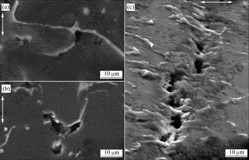
Fig.1 Detail of creep cavities on dendrite boundaries nucleated during exposure of Mg-3Y-2Nd-1Zn-1Mn at 300 ℃ and 50 MPa: (a) Single creep cavity in earlier stage of creep exposure (t/tf=0.47); (b) Coalescence of cavities in later stages (t/tf=0.67); (c) Continuous crack in crept specimen
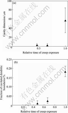
Fig.2 Time development of creep cavitation at 300 ℃ and 50 MPa: (a) Dimensions of cavities vs. relative time of creep exposure; (b) Fraction of cavitated dendritic boundaries vs relative time of creep exposure
boundaries is illustrated in Figs.2(a) and 2 (b). Increasing amount of cavitated boundaries with time of creep exposure supports the mechanism of continuous cavity nucleation and growth described by Refs.[13-14].
3.2. Grain boundary sliding
Total deformation εt during the dislocation creep is characterized by the contribution of εg-strain associated with intragranular dislocation processes within the grains and εgbs-strain due to GBS. Contribution of εds (strain due to diffusion creep) is in the dislocation creep regime insignificant and could be neglected. Contribution of GBS to the total deformation may be described as ξ=εgbs/εt. The value of sliding strain εgbs is usually calculated using expression[15]
εgbs=k' nl wl (1)
or
εgbs=k''nr vr (2)
where wl is the average value of the offsets of marker lines measured along a longitudinal traverse; nl is the number of grains per unit length along a longitudinal traverse; k' is a constant estimated theoretically between 1.4-1.6[7-8]; vr is the average value of vertical offsets measured randomly at all grain boundaries; nr is the randomly measured number of grains per unit length and k'' is a constant determined experimentally for a polished surface about 1.1[15-16].
Fig.3(a) by LM and SEM illustrates the occurrence of w-offsets on the dendritic boundaries perpendicular to the load axis in the specimen crept at 300 ℃ and 50 MPa until fracture (t/tf =1). Several grain boundaries were cavitated by the single or coalescenced cavities and especially. closer to the fracture area also continuous micro-cracks were observed (Fig 3(b)). Values of the offsets in these localities were higher than in those without cracks or cavities. Statistical evaluation of the w-offsets characterized by the relative frequency of the offset value vs. size range of the offsets shows (Fig.3(c)) that very small amount of un-cracked boundaries experienced GBS higher than 1.0 μm. On the other hand, boundaries with creep cavities and cracks exhibit significantly higher values of sliding, since the presence of cavity on the dendritic boundary enable easing the motion of neighboring grains due to the unblocking of obstacles. Observation of the specimen surface after the creep interrupted in the secondary creep regime (t/tf=0.47) shows that, no sliding is detectable by LM or SEM methods. Values of GBS (if any) are probably lower than the effective resolution of the selected metallographical methods that is about 0.01 μm (Fig.3(d)).
Fig.4(a) shows surface of the crept specimen obtained by CSLM. Line profile on Fig.4(b) illustrates the character of vertical changes across the line parallel to the load axis (line on the image). Areas where the scanning line passes over the dendritic boundaries are marked on the surface image by circles and their dimension on the corresponding profile is highlighted. Vertical v-offset due to the GBS, characterized by the elevation of the line profile, was measured randomly on several areas of the specimen surface away from the fracture area. Relative frequency of v-offset vs. offset size range is shown again in histogram in Fig.4(c).
Average values of w- and v-offsets for the boundaries without cracks were determined mathematically for specimens crept up to the final fracture. Average offset w is (0.36 ±0.15) μm; average offset v is (0.16 ±0.09) μm. Values of εgbs were calculated using Eqns.(1) and (2), with values of nl and nr taken from our previous measurements[10]. Because microstructure of as-cast alloy has a homogeneous distribution of equiaxed large dendrites (870±110) μm in all directions, nl and nr were taken as the same. The strain due to GBS εgbs obtained from Eqn.(1) for w-offset is
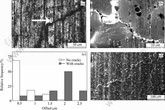
Fig.3 Occurrence of GBS on dendritic boundaries at 300 ℃ and 50 MPa (arrow shows load axis): (a) Detectable offset of marker lines (w-offset) on grain boundary of crept specimen by LM; (b) Larger offset on boundaries with cracks and cavities closer to fracture area by SEM; (c) Relative frequency of w-offsets of grain boundaries with or without cavities and cracks; (d) No offsets of marker lines observed on specimen surface after interrupted test (t/tf=0.47), SEM
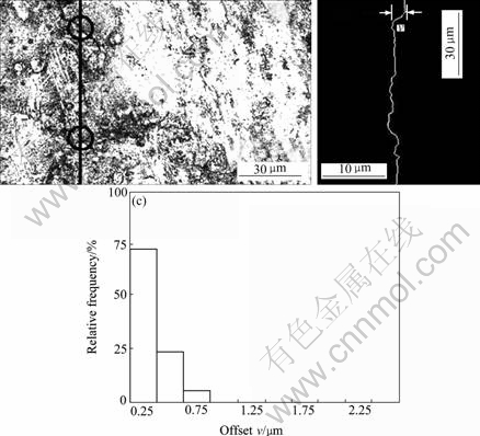
Fig.4 Measurements of vertical v-offsets on dendritic boundaries at 300 ℃ and 50 MPa (arrow shows load axis): (a) Image of measured area by CLSM (line shows line of measurement and circles show dendritic boundaries); (b) Corresponding line profile with detectable vertical v-offsets; (c) Relative frequency of v-offsets of un-cracked boundaries
0.079%, which means that contribution of GBS to the total deformation (quantified earlier; εt=2.2%) is for these particular experimental conditions not higher than ξ=5.7%. The strain εgbs obtained using Eqn.(2) gives value ξ about 1.5%. Within the experimental deviation the value of ξ obtained by both methods corresponds well to one another, and we can conclude that contribution of GBS to the total deformation is therefore insignificant. Nevertheless, although the total extent of deformation due to the GBS is small, possible contribution of εgbs to the development of strain concentrations on the boundary heterogeneities and therefore influence of εgbs to the origin of suitable conditions for cavity nucleation could not be excluded. Markedly higher values of GBS and ξ (more than 15%) were observed only in the case of cavitated boundaries closer to the fracture area.
4 Conclusions
1) Creep failure took place by the nucleation, growth and coalescence of creep cavities oriented predominantly on the boundaries perpendicular to the applied stress. Increasing amount of cavitated boundaries with time of creep exposure supports the mechanism of continuous cavity nucleation and growth.
2) Contribution of GBS to the total creep deformation is insignificant (no higher than 5.7% of εt). Markedly higher values of GBS and ξ (more than 15%) were observed only in the case of cavitated boundaries.
References
[1] Wilson R, Bettles C J, Muddle B C, Nie J F. Precipitation hardening in Mg-3% Nd (-Zn) casting [J]. Material Science Forum, 2003, 419/422: 276-281.
[2] NIE J F, GAO X, Zhu S M. Enhanced age hardening response and creep resistance of Mg-Gd alloys containing Zn [J]. Scripta Materialia, 2005, 53:1049-1053.
[3] Ping D H, Hono K, Nie J F. Atom probe characterization of plate-like precipitates in a Mg-RE- Zn-Zr casting alloy [J]. Scripta Materialia, 2003, 48:1017-1022.
[4] HONMA T, OHKUBO T, KAMADO S, HONO. Effect of Zn additions on the age-hardening of Mg-2.0Gd-1.2Y-0.0Zr alloys [J]. Acta Materialia, 2007, 55: 4137-4150.
[5] Smola B, Stulíková I, Pelcová J, ?aludová N. Phase composition and creep behavior of Mg-rare earth-Mn alloys with Zn addition [C]// Proceeding of the Conference Magnesium. Weinheim: Wiley-VCH Verlag, 2007: 67-73.
[6] Gill L R, Lorimer G W, Lyon P. The effect of zinc and gadolinium on the precipitation sequence and quench sensitivity of four Mg-Nd-Gd alloys [J]. Advanced Engineering Materials, 2007, 9: 784-792.
[7] ZOU H H. Effect of microstructure on creep behavior of Mg-5Zn-2Al(-2Y) alloy [J]. Trans Nonferrous Met Soc China, 2008, 18: 580-587.
[8] DING W, Li D, WANG Q, LI Q. Microstructure and mechanical properties of hot-rolled Mg-Zn-Nd-Zr alloys [J]. Mater Sci Eng A, 2008, 483/484: 228-230.
[9] zeng X, Zhang Y, Lu C, Ding W, wang y, zhu y. Precipitation behavior and mechanical properties of a Mg-Zn-Y-Zr alloy processed by thermo-mechanical treatment [J]. Journal of Alloys and Compounds, 2005, 395: 213-219.
[10] Hnilica F, Janík V, Smola B, Stulíková I, O?ená?ek V. Creep behavior of the creep resistant MgY3Nd2Zn1Mn1 alloy [J]. Mater Sci Eng A, 2008, 489: 93-98.
[11] Suzuki M, Kimura T, Koike J, Maruyama K. Effects of zinc on creep strength and deformation substructures in Mg-Y alloy [J]. Mater Sci Eng A, 2004, 387/389: 706-709.
[12] Suzuki M, Kimura T, Koike J, Maruyama K. Strengthening effect of Zn in heat resistant Mg-Y-Zn solid solution alloys [J]. Scripta Materialia, 2003, 48:997-1002.
[13] Dyson B F. Continuous cavity nucleation and creep fracture [J]. Scripta Metallurgica , 1983, 17:31-37.
[14] Chan K S, Page r a. Continuous creep cavity nucleation by stochastic grain-boundary sliding [J]. Journal of Materials Science, 1990, 25: 4622-4629.
[15] Langdon T G. Grain boundary sliding revisited: Developments in sliding over four decades [J]. Journal of Materials Science, 2006, 41: 597-609.
[16] Langdon T G. The role of grain boundaries in high temperature deformation [J]. Mater Sci Eng A, 1993, 166: 67-79.
(Edited by YANG You-ping)
Foundation item: Project(106/06/0252) supported by the Czech Science Foundation; Project(CTU0810412) supported by the Grant Agency of the Czech Technical University in Prague
Corresponding author: V. JAN?K; Tel: +420607555043, Fax: +420224357519; E-mail: Vit.Janik@fs.cvut.cz

