J. Cent. South Univ. Technol. (2007)03-0431-05
DOI: 10.1007/s11771-007-0084-2

Lagged strain of laminates in RC beams strengthened with fiber-reinforced polymer
HE Xue-jun(贺学军), ZHOU Chao-yang(周朝阳), LI Yi-hui(李毅卉), XU Ling(徐 玲)
(School of Civil and Architectural Engineering, Central South University, Changsha 410075, China)
Abstract: Based on the theory of concrete structure, a new expression was derived for lagged strain of fiber-reinforced polymer (FRP) laminates in reinforced concrete (RC) beams strengthened with FRP. The influence of different preloaded states and nonlinear stress-strain relationship of compressed concrete were both taken into account in this approach. Then a simplified expression was given by ignoring tensile resistance of concrete. Comparison of analytical predictions with experimental results indicates satisfactory accuracy of the procedures. The errors are less than 8% and 10% respectively when the tensile resistance of concrete is or not considered. While the maximum error of existing procedures is up to 60%.
Key words: reinforced concrete beam; bonded laminates strengthening; lagged strain; preloaded state
1 Introduction
Bonding laminates such as fiber-reinforced polymer(FRP) or steel laminates to the tensile region of reinforced cencrete(RC) beams has become a popular and effective technique for flexural strengthening in recent years[1-9]. Concrete structures are usually strengthened under preloaded states and the stress in laminates will be zero until further load is exerted, which implies lag of strain in the laminates behind that on the surface of concrete bonded. If this lagged strain is not taken into account, the practical load-bearing capacities will be over-estimated [10-16].
The influence of preloading and nonlinear contribution of the compressed concrete is ignored in the existing procedures to predict the lagged strain[12, 14-16]. The difference of the predicted values from test results fluctuates substantially and sometimes the maximum error is up to 60%. Based on the theory of concrete structure, further investigation on lagged strain of the RC beams strengthened with FRP laminates were carried out in this paper. In this procedure, the influence of different preloaded states and nonlinear stress-strain relationship of compressed concrete were fully considered, and the analytical conclusions may be helpful to improving the design in laminate- strengthening technique.
2 Calculation of lagged strain
2.1 Basic assumptions
1) The average strain of cross-section accords with the linear law before or after strengthening.
2) The stress-strain relationships of both compressed concrete and longitudinal tension reinforcement refer to the criterion of GB50010-2002.
3) The stress-strain relationship of concrete in tension is assumed to be linear. When the strain εt is not more than the ultimate value εtu(εtu=ft/Et≈2ft/Ec), the corresponding tensile stress σt equals to Etεt. Otherwise, σt equals to zero, i.e. the tensile resistance of cracked concrete will be neglected,where ft, Et and Ec are the designed tensile strength, the tensile and compressive modulus of concrete respectively.
4) Because the thickness of adhesive layer and strengthening laminates is much less than the height of cross-section, it can be neglected.
2.2 Calculation when 0≤εc0<ε0=0.002 and εs0<εy
Under this condition, the maximum compression strain εc0 of the concrete and the tension strain εs0 of the longitudinal reinforcement are less than the peak value ε0 and the yield strain εy respectively. So two cases as follows should be considered according that the concrete is cracking or not.
2.2.1 Case of εt0≤εtu=ft /Et
As shown in Fig.1(a), the maximum tension strain εt0 of the concrete is less than the ultimate tension strain εtu. According to assumption 1), the strain of longitudinal reinforcement εs0 in tension and that of strengthening laminates εf0 can be expressed as follows:
 (1)
(1)
 (2)
(2)
where xa, h and h0 are the depth of compressed zone, the depth of the RC beams and the effective depth of the RC beams respectively. Resultant force Cc of compressed concrete and the distance yc ( from the action point of Cc to the edge of the compressed zone ) are given in following expressions:
 (3)
(3)
 (4)
(4)
where b and fc are the width of RC beams and the designed axial compression strength of concrete respectively. Resultant force Ct of concrete in tension and the distance yt (from the action point of Ct to natural axis) are given by
 (5)
(5)
 (6)
(6)
When the force and moment equilibrium are considered, the following equations can be obtained.
 (7)
(7)
 (8)
(8)
where As and Es are the cross sectional area and the tensile modulus of the longitudinal reinforcement in tension respectively, and M0 is the value of pre-applied moment.
The value of xa and εc0 can be obtained from Eqns.(7) and (8), and correspondingly εf0 can be defined by Eqn.(1).
2.2.2 Case of εt0>εtu=ft /Et
When tension strain εt0 is more than εtu, concrete in tension begins to crack and it no longer carries externally applied load as shown in Fig.1(b). The lagged strain εf0 can still be calculated by Eqns.(1)-(8) , while Ct and yt should be calculated by the expression below:
 (9)
(9)
 (10)
(10)
In analytic process above, concrete in tension is considered properly to bear externally applied load, and the values of the lagged strain must be gained by solving simultaneous equations.
If the tensile resistance of concrete is ignored, i.e. Ct=0, Eqns.(9) and (10) can be written as a simple expression with the definition of A=AsEsεc0 /(fcb):

(11)
The value of xa can be calculated by solving Eqn.(11) directly, and the lagged strain εf0 can be obtained by

(12)
2.3 Calculation when 0≤εc0<ε0=0.002 and εs0≥εy
In this case, reinforcement in tension has yielded and its resultant force Ts equals Asfy (fy is the designed yield strength of the longitudinal reinforcement in tension). The resultant forces Cc and Ct, and the corresponding yc and yt can be defined by Eqns.(3), (9) and (4), (10) respectively. Then the following equations are obtained:
 (13)
(13)
 (14)
(14)
Once the values of xa and εc0 are given by solving simultaneous equations of Eqns.(13) and (14), correspondingly the lagged strain εf0 can be defined by Eqn.(1) .
If the tensile resistance of concrete is ignored, Eqns.(13) and (14) can be rewritten as follows with the definition of B=(fyAs)2/[fcb(fyAsh0-M0)]:
 (15)
(15)
Then εc0/ε0 can be obtained by solving Eqn.(15), and the lagged strain εf0 can be expressed as:
 (16)
(16)
2.4 Calculation when ε0<εc0≤εcu=0.0033 and εs0<εy
Under this condition, the longitudinal reinforcement in tension has not yielded, which means that the reinforcement is sufficient and usually it is not necessary to strengthen the RC beams.
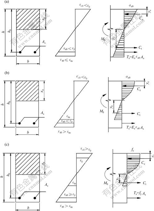
Fig.1 Cross sections with stress and strain distribution and force profile of strengthened beams bearing moment of M0
(a) Case of εc0<ε0, εt0≤εtu, εs0<εy; (b) Case of εc0<ε0, εt0>εtu, εs0<εy; (c) Case of εc0≥ε0, εt0>εtu, εs0≥εy
2.5 Calculation when ε0≤εc0≤εcu=0.003 3 and εs0≥εy
As shown in Fig.1(c), the longitudinal reinforcement in tension has yielded and the maximum compression stress of concrete has exceeded the peak value ε0. So the resultant force Ts equals to Asfy. Cc and the corresponding yc are given by Eqns.(17) and (18) respectively.
 (17)
(17)
 (18)
(18)
Ct and the corresponding yt are still defined by Eqns.(9) and (10). If the equilibrium conditions of the cross-section are considered as shown in Fig.1(c), two equations can be obtained.
 (19)
(19)
 (20)
(20)
By solving simultaneous equations of Eqns.(19) and (20), the values of xa and εc0 are obtained. The lagged strain εf0 can be still defined by Eqn.(1).
If the tensile resistance of concrete is ignored (i.e. Ct=0), Eqns.(19) and (20) can be written simply as Eqn.(21) below:
 (21)
(21)
where D=2M0fcb-2fyAsbfch0+(fyAs)2. The value of ε0/εc0 can be easily calculated by solving Eqn.(21), and then the solution of the lagged strain εf0 is given by
 (22)
(22)
3 Experimental verification
Simply supported RC beams strengthened with CFRP laminates in different preloaded states were investigated. Application of load was designed in a four-point bending system. All specimens had same rectangular cross section 300 mm×600 mm. The length and calculated length were 6 200 mm and 6 000 mm respectively. The measured cubic strength fcu and elasticity modulus Ec of concrete were 28.8 MPa and 29.1 GPa, respectively. The longitudinal reinforcement in tension was 4Φ25HRB335 (fy=417 MPa, fu=573.47 MPa, εy=2 085×10-6, Es=200 GPa). The handling reinforce- ment was 2Φ10 HPB235, and the stirrup was Φ10@150 mm HPB235 (fy=242.2 MPa, fu=356.7 MPa, εy=1153.3×10-6, Es=210 GPa). The net thickness of protective cover of the longitudinal reinforcement in tension was 40 mm and that of the handling reinforcement was 35 mm. Strain gauges were installed on the tensile bottom and flank of the beams at the midspan to measure the strain at cross section in different preloaded states. In every preloaded state, the measured value of extreme fiber in tension was the lagged strain of CFRP laminates.
Table 1 shows the comparison between lagged strain calculated by the methods in this paper and in Refs.[12, 14-16]. When the concrete has not cracked before strengthening, with M0=0.11Mu as an example, the maximum absolute value of errors reaches about 60% if the methods of references above except Ref.[16] is used. However, using the method considering tensile resistance of concrete in this paper and the method from Ref.[16], errors are all less than 10%. On the other hand, if the RC beams has cracked before strengthening, the errors of methods from Refs.[12, 14-16] all reduce but fluctuate greatly. For example, when M0 equals 0.21Mu, 0.36Mu, 0.65Mu and 0.83Mu, the variation range of errors is from 11% to -42%, from -10% to 20%, from -10% to 23% and from -10% to 23% respectively. In contrast, the absolute values of errors of the methods in this paper are all less than 8% whether or not the tensile resistance of concrete is considered.
The approach proposed here is proved to be suitable for the evaluation of the lagged strain by comparing the theoretical values with the test results. If uncracked beams are strengthened, the theoretical values agree better with the test results when the tensile resistance of concrete is considered (Fig.2).To take M0 = 0.11Mu for example, the error is less than 8% whereas the error of the method without considering the tensile resistance of concrete reaches to 62.52%(Table 1). The difference results from that concrete in tension help resist quite a part of bending moment before cracking, which should not be ignored. Under the condition of strengthening after cracking, the lagged strain calculated by author’s methods accords with the test results very well no matter the tensile resistance of concrete is taken into consideration or not. For example, when M0 varies from 0.21Mu to 0.83Mu, the variation range of error for the
Table 1 Comparison of lagged strains predicted by different approaches

Notes: Mu is the ultimate bending moment of RC beams, and M0 is the value of pre-applied moment. The value of error equals (theoretical value- experimental data)×100% / experimental data.
former is from -2.2% to 2.3% and that for the latter is from -4% to 8.3% (Table 1). This is because that cracked concrete in tensile zone has gradually gone out of work with increasing the external load and the effective area of concrete in tension decreases rapidly. For this reason, the effect of tensile resistance of concrete on the lagged strain is marginal and can be omitted.

Fig.2 Comparison of lagged strain between test results and theoretical values calculated by author’s methods
1―Test results; 2―Lagged strain values calculated by the method considering the tensile resistance of concrete;
3―Lagged strain values calculated by the method ignoring the tensile resistance of concrete
4 Conclusions
1) The existing methods to calculate Lagged strain of laminate-strengthened RC beams are all approximate because the influence of different preloaded states is not fully considered. The errors are great and the maximum absolute value reaches 60%.
2) A new expression and its simplified form are developed for the calculation of lagged strain. The tensile resistance of concrete is not considered in the latter. Both the methods are applicable for all preloaded states of RC beams strengthened with FRP laminates. Especially the accuracy of the former is satisfactory, and the absolute values of errors are all less than 8%.
3) In case of strengthening before cracking, it’s inadvisable to ignore the tensile resistance of concrete. For simplification the lagged strain may be calculated by the method in Ref.[16]. In case of strengthening after cracking, the lagged strain can be calculated by the method ignoring tensile resistance of concrete in this paper, namely Eqns.(12), (16) or (22). The calculation errors in the two cases above are both less than 10%.
References
[1] HE Xue-jun, ZHOU Chao-yang. Analysis and calculation of interfacial bonding shear stress of reinforced concrete beams strengthened with plates[J]. Journal of Central South Universit: Scinece nd Technologyy, 2005, 36(2): 340-343. (in Chinese)
[2] ZHOU Chao-yang, HE Xue-jun, WANG Xing-guo, et al. Some problems of structural strengthening technology with FRP and it’s development[J]. Construction Technology, 2003, 23(6): 4-6. (in Chinese)
[3] VINCENZO C, GIUSEPPE S. Shear strength of RC beams strengthened with bonded steel or FRP plates [J]. ASCE Journal of Structural Engineering, 2001, 127(4): 367-373.
[4] ALESSANDRA A, ENRICO S, SUCHART L. Role of bond in RC beams strengthened with steel and FRP plates[J]. ASCE Journal of Structural Engineering, 2001, 127(12): 1445-1452.
[5] HUI S S, TENG J G, YANG J. Interfacial stresses in beams and slabs bonded with thin plate[J]. ASCE Journal of Engineering Mechanics, 2001, 127(4): 399-406.
[6] JOSEPH R Y, SHAWN P G. Flexural design methodology for concrete beams reinforced with fiber-reinforced polymers[J]. ACI Structural Journal, 2002, 99(3): 308-316.
[7] THOMAS G H, YOO J K, JOHN K, et al. Bond of surface-mounted fiber-reinforced polymer reinforcement for concrete structure[J]. ACI Structural Journal, 2003, 100(5): 557-564.
[8] BYUNG H O, JAE Y C, DAE G P. Failure behavior and separation criterion for strengthened concrete members with steel plates[J]. ASCE Journal of Structural Engineering, 2003, 129(9): 1191-1198.
[9] LAURA D L. Anchorage length of near-surface mounted fiber-reinforced polymer rods for concrete strengthening-analytical modeling[J]. ACI Structural Journal, 2004, 101(3): 375-386.
[10] YEONG S S, CHADON L. Flexural behavior of reinforced concrete beams strengthened with carbon fiber-reinforced polymer laminates at different levels of sustaining load[J]. ACI Structural Journal, 2003, 100(2): 231-239.
[11] CHEN Li-ying, GAO Ri. Research on bending capacity of CFRP reinforced concrete structure at twice loading[J]. Journal of Northern Jiaotong University, 2003, 27(1): 80-83. (in Chinese)
[12] CECS146:2003. Technical specification for strengthening concrete structures with carbon fiber reinforced polymer laminate[S]. Beijing: China Plan Press, 2003. (in Chinese)
[13] ZHENG Guo-dong, HOU Fa-liang. Effect of secondary loading on calculation results of normal section’s ultimate bearing capacity of RC beams strengthened with CFRP[J]. Industrial Construction, 2004, 34(5): 73-75. (in Chinese)
[14] ZHOU Fen-sheng, ZHANG Zi-mao. Analysis of reinforced concrete beams strengthened with FRP[J]. Journal of Northern Jiaotong University, 2002, 26(4): 24-28. (in Chinese)
[15] HU Kong-guo, CHEN Xiao-bing, YUE Qing-rui, et al. Calculation of normal section’s ultimate bearing capacity of RC beams strengthened with CFRP under quadratic loading[J]. Building Structure, 2001, 31(7): 63-65. (in Chinese)
[16] WANG Wen-wei, ZHAO Guo-fan, HUANG Chen-da, et al. An experimental study of strengthening of initially loaded reinforced concrete beams using CFRP sheets[J]. Engineering Mechanics, 2004, 21(4): 172-178. (in Chinese)
(Edited by YUAN Sai-qian)
Foundation item: Project(2002G043) supported by the Science & Technology Research Program of Chinese Railway Ministry; Project (05JJ30101) supported by the Natural Science Foundation of Hunan Province, China
Received date: 2006-10-24; Accepted date: 2006-12-27
Corresponding author: HE Xue-jun, Doctoral candidate, Associate professor; Tel: +86-731-2656678; E-mail: Junxuehe@126.com

