þ�Ͻ����Ի�ѧ���л�ѧ��Ni-Sn-P���ɲ�Ľṹ������
��Դ�ڿ����й���ɫ����ѧ��(Ӣ�İ�)2015���5��
�������ߣ��� ΰ ������ ��С�� �Թ��� ������ �� ��
����ҳ�룺1506 - 1516
�ؼ��ʣ�þ�Ͻ�Ni-Sn-P�����ɲ㣻��ʴ�ԣ����Ի�ѧ��
Key words��magnesium alloy; Ni-Sn-P; transition layer; corrosion resistance; acid electroless plating
ժ Ҫ�������и���ʴ�ԵĻ�ѧ��Ni-Sn-P��Ԫ�Ͻ���ɲ�Ӧ����þ�Ͻ����Ի�ѧ�������̡�ͨ��SEM��XRD�Ա��о���ͳ���Ի�ѧ��Ni-P���ɲ�������Ni-Sn-P���ɲ�ı�����ò������֯�������Թ��ɲ���AZ31þ�Ͻ�֮��Ľ���������ÿ�϶�ʡ����ɲ���pH=4.5�����Ի�ѧ������Һ�еĶ���λ�������ߺ͵绯ѧ�����迹(EIS)�Լ�10% HCl����ʵ���о����ɲ����ʴ�ԡ�������������ɲ����ֱ����þ�Ͻ����������Ի�ѧ��Ni-P�Ͻ��DZز����ٵġ�����ͬ���(~6 ��m)�����£��봫ͳ��ѧ��Ni-P���ɲ���ȣ���ѧ��Ni-Sn-P���ɲ�ķǾ����̶ȸ��ߣ�����ƽ�����ܣ��Ʋ���϶�������ǿ����ʴ�Ը��ߡ�����Ҫ���ǣ��Ի�ѧ��Ni-Sn-PΪ���ɲ���Գɹ�����þ�Ͻ�����Ʊ����Ի�ѧ��Ni-P�Ͻ�Ʋ㡣
Abstract: An electroless ternary Ni-Sn-P transition layer with high corrosion resistance was applied for acid electroless nickel plating on magnesium alloys. The surface morphologies and microstructure of the traditional alkaline electroless Ni-P and novel Ni-Sn-P transition layers were compared by SEM and XRD, and the bonding strengths between the transition layers and AZ31 magnesium alloys were tested. The corrosion resistance of the samples was analyzed by porosity test, potentiodynamic polarization, electrochemical impedance spectroscopy (EIS) in acid electroless solution at pH 4.5 and immersion test in 10% HCl. The results indicate that the transition layer is essential for acid electroless plating Ni-P coatings on magnesium alloys. Under the same thin thickness (~6 ��m), the electroless Ni-Sn-P transition layer possesses superior properties to the traditional Ni-P transition layer, including high amorphization, smooth and dense surface without pores, enhanced bonding strength and corrosion resistance. Most importantly, acid electroless Ni-P coatings can be successfully deposited on magnesium alloys by using Ni-Sn-P transition layer.
Trans. Nonferrous Met. Soc. China 25(2015) 1506-1516
Wei LIU1,2, Dong-duo Xu1, Xiao-yue DUAN2, Guo-sheng ZHAO1, Li-min CHANG1, Xin LI3
1. Key Laboratory of Preparation and Application of Environmental Friendly Materials, Ministry of Education, Jilin Normal University, Siping 136000, China;
2. College of Environmental Science and Engineering, Jilin Normal University, Siping 136000, China;
3. State Key Laboratory of Urban Water Resources and Environment, Harbin Institute of Technology, Harbin 150090, China
Received 24 May 2014; accepted 27 October 2014
Abstract: An electroless ternary Ni-Sn-P transition layer with high corrosion resistance was applied for acid electroless nickel plating on magnesium alloys. The surface morphologies and microstructure of the traditional alkaline electroless Ni-P and novel Ni-Sn-P transition layers were compared by SEM and XRD, and the bonding strengths between the transition layers and AZ31 magnesium alloys were tested. The corrosion resistance of the samples was analyzed by porosity test, potentiodynamic polarization, electrochemical impedance spectroscopy (EIS) in acid electroless solution at pH 4.5 and immersion test in 10% HCl. The results indicate that the transition layer is essential for acid electroless plating Ni-P coatings on magnesium alloys. Under the same thin thickness (~6 ��m), the electroless Ni-Sn-P transition layer possesses superior properties to the traditional Ni-P transition layer, including high amorphization, smooth and dense surface without pores, enhanced bonding strength and corrosion resistance. Most importantly, acid electroless Ni-P coatings can be successfully deposited on magnesium alloys by using Ni-Sn-P transition layer.
Key words: magnesium alloy; Ni-Sn-P; transition layer; corrosion resistance; acid electroless plating
1 Introduction
Magnesium alloys present desirable physical and mechanical properties, including high specific strength, low density, good electrical and thermal conductivity, excellent anti-shock resistance, effective electromagnetic shielding and easy recycling. Unfortunately, the poor corrosion resistance has greatly restricted their applications in many industry fields [1,2]. To improve the corrosion resistance of magnesium alloys, it is usual to provide a protective surface treatment, including electroplating, electroless plating, micro-arc oxidation, conversion coating, laser surface cladding, gas phase plating, anodizing, and organic/polymer coatings [3-10]. Among them, electroless nickel-based plating is considered an effective technology to modify the physical and chemical properties of the substrate due to its excellent performances, low cost as well as relatively simple equipment [11-13].
In the electroless plating industry, electroless Ni-P coatings with good corrosion resistance are normally prepared from acid baths (pH < 5.0) which have higher solution stability and more compact coating surface, but such applications have always been carried out on steel or copper substrate [14-16]. However, there are few reports on acid electroless plating Ni-P coating on magnesium alloy due to its high chemical reactivity which makes it prone to corrosion during formation of the coating [17,18]. So, as for preparation, utilizing a transition layer is necessary in acid eletroless plating Ni-P alloy coatings on magnesium alloys.
With regard to the transition layer, several materials are commonly used, such as zinc immersion, conversion coatings and pre-coated alkaline electroless Ni-P layer. However, the zinc immersion procedure is complicated and the next step of plating copper with cyanide is harmful on human health and environment [19]. Compared with the previous treatment, the conversion coating is nontoxic, but the procedure, including chemical conversion, activation, sensitization and acid electroless plating, is cumbersome and the cost of production is high, which is not propitious to the demand of wholesale industrialization [20]. For the last one, the corrosion resistance of alkaline electroless Ni-P transition layer is directly related to the specified thickness that the transition layer can resist corrosion in acid solution [21], which will result in low bonding ability between the layer and the substrate. Taking into consideration of various elements, using electroless coating as transition layer on magnesium alloy before acid electroless Ni-P alloy coating is technologically accessible and industrially practical, while it is also to propose high requirements for the quality of the electroless transition layer.
Based on the electroless Ni-P binary alloy, a third element such as Sn, Cu, W, Zn, Fe and Mo is usually introduced to form a ternary alloy for meeting some special demands [22-24]. Among them, Ni-Sn-P ternary alloy coatings have been widely applied in electronic components such as leading wire, magnetic recording medium, PCB, and anode for lithium-ion batteries, which is mainly due to their excellent corrosion resistance, low porosity, good heat-resistance and weldability [25]. But according to the available literature, the introduction of tin poisons the chemical baths and then the plating rate of electroless Ni-Sn-P coating is greatly decelerated that it will take a long time to get single electroless Ni-Sn-P layer with sufficient thickness to protect the magnesium alloy substrate, which impedes the independent application of electroless Ni-Sn-P coating [22]. Taking into account the dual characteristics of transition layer, i.e., high corrosion resistance and thin thickness, electroless Ni-Sn-P coating is properly in line with these requirements. Nevertheless, to the best knowledge of the present literatures, there is no report about using electroless Ni-Sn-P ternary alloy coating as transition layer applied in acid electroless Ni-P coating on magnesium alloy.
In this work, for a better illustration of the feasibility of acid electroless Ni-P alloy coating on magnesium alloy by using electroless Ni-Sn-P transition layer, the microstructures of traditional alkaline electroless Ni-P transition layer and present Ni-Sn-P transition layer were compared. In addition, the corrosion resistance of both transition layers in acid electroless solution (pH 4.5) was investigated.
2 Experimental
2.1 Preparation of specimens
Die-cast AZ31B magnesium alloy (3.19% Al and 0.81% Zn, mass fraction) was used as substrate. The specimens were cut into coupons with dimensions of 25 mm �� 40 mm �� 0.6 mm. The technological process of acid electroless plating Ni-P alloy coating followed the sequence: alkaline cleaning �� one-step pickling- activation �� electroless plating Ni-Sn-P transition layer �� acid electroless plating Ni-P alloy coating. The specific details are given in Table 1.
Table 1 Technological process of acid electroless plating Ni-P alloy coating

2.2 Characterization
The plating rate of the specimens was calculated with gravimetric method according to the following equation:
 (1)
(1)
where �� (mm/h) is the plating rate, m1 (g) and m2 (g) are the masses before and after electroless plating transition layers, respectively, m (8.1 g/cm3) is the density of the specimens, S (cm2) is the specimen area, and t (h) represents the plating time.
The morphologies of the specimens were characterized by a scanning electron microscope (SEM, Hitachi S-570) and a digital camera. The phase composition of the specimens was analyzed by X-ray diffraction spectrometer (XRD, Rigaku D/Max-3C) using a Cu Ka radiation generated at 45 kV and 35 mA.
To evaluate the bonding strengths of the transition layers to the substrates, the ASTM D3359-02 standard test method for measuring adhesion by tape test was employed [26,27]. The test was accomplished by scratching 1 mm-wide parallel lines vertically and horizontally on the specimens with a steel knife having a cutting edge angle of 30��. The scratched specimen was then adhered tightly with the tape for about 70 s, and then the tape was peeled rapidly in a direction parallel to the layer surface. The bonding strength can be evaluated according to the classification of adhesion test results. A poor bonding strength can be found when the layer is broken and peeled from the substrate, whereas, a good bonding strength can be found when merely scratched marks are revealed on the surface.
2.3 Evaluation of corrosion resistance
In order to evaluate the porosity of the specimens, a porosity test was carried out. The operation process of the method was briefly explained in Ref. [28]. That is, a filter paper with an area of 1 cm2 was dipped into an aqueous solution containing 10 g/L NaCl, 106 g/L ethanol and 0.1 g/L phenolphthalein. And then the chemical-soaked filter paper was pasted onto the coating for 10 min. After removing the filter paper, red areas were noted on the coating surface. The porosity of the coating was evaluated relatively by the ratio of red area to the zone area pasted by the filter paper.
To further evaluate the corrosion resistance, electrochemical measurements of the specimens were investigated by potentiodynamic polarization and electrochemical impedance spectroscopy (EIS) on Autolab PGSTAT302 potentiostat (made in Netherlands). A three-electrode electrochemical cell was used employing the specimen as working electrode with an exposed area of 1 cm2, a Pt plate as counter electrode and a saturated calomel electrode (SCE) as reference electrode, respectively. The tests were performed at 25 ��C in the simulated acid electroless Ni-P solution (pH=4.5). The polarization curves were obtained starting from ~300 mV (more negative than open circuit potentials) to more positive potentials at a scanning rate of 1 mV/s. EIS measurements were carried out with the amplitude of 10 mV in the frequency ranging from 10 kHz to 0.1 Hz. Acid immersion test in the 10% HCl solution at room temperature was carried out for the specimens. The time interval between the start of the acid immersion test and the first hydrogen bubble arising from the layer surface was used to represent the corrosion resistance of the transition layers on the magnesium alloy substrate [29].
3 Results and discussion
3.1 Direct acid electroless plating Ni-P coating after one-step pickling-activation
Figure 1 exhibits the surface morphologies of direct acid electroless plating Ni-P coatings for 5 min and 30 min respectively after one-step pickling-activation. When there is no transition layer on the surface of magnesium alloy, after direct acid electroless plating Ni-P coating for 5 min, the magnesium alloy begins to be corroded, and obvious holes emerge. With prolonging the time to 30 min, the corrosion phenomenon is aggravated, which makes the surface look like a pile of tattered cotton. Therefore, it is infeasible to produce an acid electroless Ni-P coating directly after one-step pickling-activation, that is, the surface transition layer plays a crucial role especially in acid electroless plating Ni-P coating on magnesium alloy.

Fig. 1 Surface morphologies of direct acid electroless Ni-P coatings after one-step pickling-activation
3.2 Alkaline electroless Ni-P and Ni-Sn-P transition layers
3.2.1 Plating rate
In order to protect magnesium alloy substrate from corrosion in acid solution, transition layers were pre-produced before acid electroless Ni-P coating. Figure 2 displays the comparative thicknesses of alkaline electroless Ni-P and Ni-Sn-P transition layers. The thicknesses of both layers seem to linearly increase as a function of the plating time. The calculated and experimental results show that the plating rate of alkaline electroless Ni-P transition layer comes to a value of about 18 mm/h, but the main disadvantage is the decreased solution stability. As for electroless Ni-Sn-P transition layer, the plating rate on magnesium alloy is approximately 7 mm/h. This is mainly due to the synergistic effect of SnO32- anion on the specimen surface with consequent inhibition and poisoning of the catalytic reaction [22,24,30]. But at the same time, the stability of the solution is increased. In addition, considering that the thickness of transition layer is always not too thick, the plating rate of 7 mm/h is acceptable to the electroless Ni-Sn-P transition layer.

Fig. 2 Plating rates of alkaline electroless Ni-P and Ni-Sn-P transition layers
3.2.2 Surface morphologies
Figure 3 presents the surface morphologies of alkaline electroless Ni-P and Ni-Sn-P transition layers. It can be clearly observed that both alkaline electroless Ni-P and Ni-Sn-P transition layers disclose typical cauliflower-like surface morphologies with lots of irregular nodules on the surface. From the comparison, for alkaline electroless Ni-P layer (Fig. 3(a)), the large nodule tissues consist of numerous sub-particles, and defects can also be observed. Small slits mainly distribute at the boundaries of the every tiny nodule, and interfacial atoms often have high activity, which easily leads to corrosion of the coating from the boundaries of nodules. This structure increases porosity as well as extends contact area between the corrosive media and coating surface, thus results in the decrease of corrosion resistance. Figure 3(b) exhibits a smooth, dense coverage of the electroless Ni-Sn-P transition layer on magnesium alloy substrate with characteristics of closer nodular particle arrangement and lower porosity. As shown in Fig. 2, the plating rate of Ni-Sn-P alloy is lower due to the co-plating of Sn with Ni in the coating, which should lead to the reduction in defects. Thus, the surface morphology of Ni-Sn-P transition layer is more compact and non-porous to effectively protect the magnesium alloy substrate from corrosion of subsequent acid solution.

Fig. 3 SEM micrographs of alkaline electroless Ni-P (a) and Ni-Sn-P (b) transition layers with thickness of about 6 ��m
3.2.3 Phase structure of transition layers
Figure 4 shows the XRD patterns of AZ31 magnesium alloy, alkaline electroless Ni-P and Ni-Sn-P transition layers. As shown in Fig. 4, the sharp diffraction peaks of Mg from AZ31 magnesium alloy can be clearly observed. After electroless plating Ni-P and Ni-Sn-P transition layers, the signals from the magnesium alloy substrate are highly suppressed but remain dominant due to the thin thickness (~6 mm) of the coatings. Apart from the high intensity peaks of magnesium alloy, both of the diffraction patterns have a broad peak at 2q=45��, which indicates that the alkaline electroless Ni-P and Ni-Sn-P transition layers are amorphous nickel alloys. XRF analysis reveals that P content of Ni-P transition layer is 8.72% (mass fraction), while the P and Sn contents of Ni-Sn-P transition layer are 7.85% and 2.24% (mass fraction), respectively. The results are corresponding to the amorphous structure of nickel-based coating, in which P content is in medium level (5%-8%) [22,31]. It can be found that the diffraction intensity of Ni-Sn-P transition layer is reduced significantly compared with that of Ni-P transition layer, while the full width at half maximum (FWHM) of the diffraction peak is evidently broadened, indicating that the amorphization of Ni-Sn-P transition layer is strengthened. For the alkaline electroless binary Ni-P coating, there are two kinds of atomic bonds, Ni��P and Ni��Ni. The bond Ni��P is favorable for glass formation. P is a favorable element for amorphous formation. After adding Sn into Ni-P system, two new kinds of atomic bonds, Ni��Sn and Sn��P, are formed. Sn is also a favorable element for amorphous formation. Therefore, though the P content is nearly the same (8.72% and 7.85%) in alkaline electroless Ni-P and Ni-Sn-P transition layers, the amorphous formation ability of Ni-Sn-P layer is improved, which is free of crystal boundaries and absence of the defects in crystalline alloys such as dislocations, stacking faults and segregation [22,25]. This structure can reduce electrochemical inhomogeneity on coating surface and then improve the corrosion resistance of Ni-Sn-P transition layer.
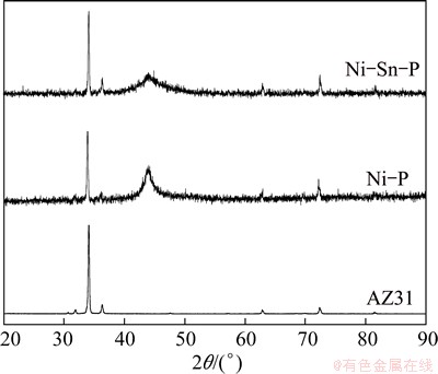
Fig. 4 XRD patterns of alkaline electroless Ni-P and Ni-Sn-P transition layers with thickness of about 6 ��m
3.2.4 Bonding strength of transition layers
Considering that the bonding strength between transition layer and magnesium alloy substrate has profound effect on the quality of the following acid electroless Ni-P alloy coating, the bonding strengths of the alkaline electroless Ni-P and Ni-Sn-P transition layers were evaluated by the ASTM D3359-02 standard test, and the results are shown in Fig. 5. As can be seen from the surface of cross-cut area where flaking has occurred for six parallel cuts, the alkaline electroless Ni-P coating has peeled along the edges of cuts in large ribbons and whole squares have detached, and the affected area is greater than 60% (see Fig. 5(a)). On the other hand, merely scratched marks can be observed on the alkaline electroless Ni-Sn-P coating. The edges of cuts are completely smooth and none of the squares of the lattice is detached (see Fig. 5(b)). This means that the bonding strength of the alkaline electroless Ni-Sn-P coating to the AZ31B surface is obviously higher than that of alkaline electroless Ni-P coating, which is favorable to obtain qualified acid electroless Ni-P alloy coating.

Fig. 5 Optical images showing poor and good bonding strength of alkaline electroless Ni-P (a) and Ni-Sn-P (b) transition layers to substrate (Red boxes note peeled areas)
3.2.5 Corrosion resistance of transition layers
To validate whether the electroless nickel-based alloy coatings are suitable for use as transition layers in acid electroless Ni-P alloy coating on AZ31 magnesium alloys, the corrosion resistances of alkaline electroless Ni-P and Ni-Sn-P coatings were investigated by the porosity test, electrochemical measurements in simulated acid electroless Ni-P plating solution (pH=4.5) instead of traditional 3.5% NaCl solution and the hydrochloric acid immersion test.
Since the electrochemical potential of nickel is nobler than that of magnesium, the substrate is prone to galvanic corrosion [17]. The electroless nickel-based transition layers are cathodes to the substrate, therefore, they can provide a physical barrier against corrosion attack. But if the corrosive media connect the nickel coating to the magnesium alloy substrate, local corrosion cells will form on the surface and then result in pit [14,15]. Hence, the electroless nickel-based transition layers on magnesium alloy must be uniform, adherent and pore-free as much as possible. The porosities (represented by the red area) of the alkaline electroless Ni-P and Ni-Sn-P coatings were estimated by the porosity test [28]. The results show that although the layers are thin (about 6 mm), no red spots are found in the alkaline electroless Ni-Sn-P transition layer. As for the compared alkaline electroless Ni-P transition layer, the red area percentage exceeds 80%. This is mainly due to the lower plating rate caused by codeposition of Sn with Ni in the layer. Thus, the Ni-Sn-P transition layer is more uniform and compact to effectively protect the magnesium alloy from being corroded.

Fig. 6 Potentiodynamic polarization curves of alkaline electroless Ni-P and Ni-Sn-P transition layers in acid electroless Ni-P plating solution (pH=4.5)
Table 2 Extrapolation results of polarization curves of alkaline electroless Ni-P and Ni-Sn-P transition layers
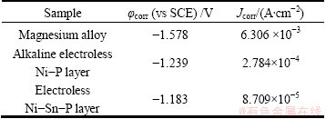
Figure 6 shows the potentiodynamic polarization curves of AZ31 magnesium alloy substrate, alkaline electroless Ni-P and Ni-Sn-P transition layers. The corrosion parameters such as corrosion potential (��corr) and corrosion current density (Jcorr) are extrapolated from the polarization curves, and the results are summarized in Table 2. The bare substrate exhibits the most negative ��corr value and the maximum Jcorr value, indicating a high corrosion rate and high chemical reactivity of AZ31 magnesium alloy. After alkaline electroless plating Ni-P and Ni-Sn-P transition layers, the ��corr values are shifted in positive direction by 339 and 395 mV, respectively, compared with those of the bare magnesium alloy, while the Jcorr values are decreased by an order of magnitude and two orders of magnitude compared with that of the bare magnesium alloy, respectively, suggesting better anticorrosive properties compared with that of the bare magnesium alloy. Among the three types of samples, the noblest ��corr value and minimum Jcorr value of Ni-Sn-P transition layer indicate the highest thermodynamic stability and the lowest corrosion rate in acid solution. These results indicate that the corrosion resistance of magnesium alloy is greatly improved by electroless Ni-Sn-P transition layer.
To further evaluate the effects of alkaline electroless Ni-P and Ni-Sn-P coatings as transition layers, EIS measurements were performed in acid electroless Ni-P plating solution at pH 4.5, and the Nyquist and Bode plots of the EIS spectra are shown in Fig. 7.

Fig. 7 EIS spectra of alkaline electroless Ni-P and Ni-Sn-P transition layers in acid electroless Ni-P plating solution (pH=4.5)
The impedance spectra of the Ni-P and Ni-Sn-P transition layers exhibit one capacitive loop, but the semicircle diameters are different. It can be clearly seen that, the semicircle diameter of Ni-P transition layer is smaller, and the scatters appear at the end of the capacitive loop, which means that the coating has already been corroded. Whereas, the semicircle diameter of Ni-Sn-P transition layer is larger without any scatters, indicating better corrosion resistance of Ni-Sn-P transition layer. The impedance modulus |Z| of Ni-Sn-P transition layer (1680 W��cm2) is 1.4 times of that of Ni-P transition layer (1210 W��cm2), which also clearly shows that the corrosion resistance of Ni-Sn-P transition layer is better than that of Ni-P transition layer in acid electroless plating solution at pH 4.5. The time constant in the high frequency range reflects the anti-corrosion properties of the electroless coating, while the constant in the low frequency range characterizes the diffusion of electrolyte through the pores on coating surface. For alkaline electroless Ni-P transition layer, corrosion phenomenon may have occurred according to the existence of the scatters at the low frequency. The equivalent circuit in Fig. 8(a) (Model A) was used for fitting EIS data of Ni-P layer, where Rs is the solution resistance; Qp is the double-layer capacitance and Rp is the polarization resistance; at this point, the alkaline electroless Ni-P layer has contacted with corrosive solution, forming corrosion pits, thus, Qo and Ro represent the constant phase angle element of corrosion product and its pore resistance, respectively. For the electroless Ni-Sn-P transition layer, no scatters appear at the low frequency range, Model B (Fig. 8(b)) was employed to fit the experimental data. There is only one time constant corresponding to mass transfer process of double-layer, which states that no corrosion occurs on the surface of Ni-Sn-P transition layer. It can be seen that the equivalent circuits fit the experimental data well in most of the frequency range, indicating that the equivalent circuits of Fig. 8 are suitable, whereas the fitting values are listed in Table 3.
The polarization resistance, Rp, is an important parameter, as shown in Fig. 8 and Table 3. The Rp value of electroless Ni-Sn-P transition layer is 1.6 times of that of Ni-P transition layer. Provided the solution resistance is a constant value, the Rp value is inversely proportional to the layer porosity according to the definition of the electric resistance. Thus, large Rp value indicates that the layer porosity of Ni-Sn-P coating is far less than that of Ni-P coating. This is in accordance with the results of surface morphologies and structure analyses shown in Figs. 3 and 4, which show that the Ni-Sn-P transition layer is compact with little pores so as to prevent the permeation of corrosion media. The polarization resistance, Rp, is also inversely proportional to corrosion current density, Jcorr. Thus, the higher the Rp value is, the lower the Jcorr value is, implying that the corrosion resistance of Ni-Sn-P transition layer is superior to that of Ni-P transition layer.

Fig. 8 Equivalent circuit used to fit EIS spectra of alkaline electroless Ni-P (a) and Ni-Sn-P (b) transition layers
Meanwhile, the immersion test in the 10% HCl solution at room temperature was carried out for the alkaline electroless Ni-P and Ni-Sn-P transition layers. The time interval between the start of the test and the first hydrogen gas bubble arising from the layer surface was used to evaluate the corrosion resistance of the transition layers on AZ31 substrate. Under the same thin thickness, the alkaline electroless Ni-P transition layer is immediately corroded, producing a volume of bubbles just immersing in the 10% HCl solution, whereas the alkaline electroless Ni-Sn-P transition layer can endure 15 min without corrosion of the magnesium alloy substrate. The test results further indicate that the corrosion resistance of alkaline electroless Ni-Sn-P transition layer is superior to that of alkaline electroless Ni-P transition layer in severe corrosion environment, which is consistent with the porosity and electrochemical measurements.
Table 3 EIS fit results for alkaline electroless Ni-P and Ni-Sn-P transition layers

It is well known that the corrosion resistance of an alloy coating is dependent upon the plating rate, microstructure and protective behavior of a surface protective film [32]. When the coating is sufficiently dense, it can efficiently protect the substrate from corrosion by acting as a physical shield between the metal and the corrosive media. If the coating is not dense, its shielding effect will decrease significantly. From the analyses of SEM and XRD results, the alkaline electroless Ni-Sn-P transition layer possesses more uniformity and compact microstructure with little pores, which can prevent the permeation of acid solution and then protect the substrate from being corroded by acting as a physical shield. Meanwhile, during the process of electroless plating Ni-Sn-P transition layer, the low forming speed reduces the surface defects and the incorporation of Sn into the coating makes the degree of amorphization strengthened, which improves the corrosion resistance compared with the Ni-P transition layer. With codeposition of Sn, the porosity of nickel-based coating is reduced significantly, and the corrosion rate becomes distinctly slower. The above analyses show that electroless Ni-Sn-P transition layer is beneficial for subsequent acid electroless plating Ni-P alloy coatings on magnesium alloys.
From the comparison of corrosion resistance between alkaline electroless Ni-P and Ni-Sn-P transition layers, it can be safely concluded that the Ni-Sn-P transition layer can provide better protection to a certain extent for the magnesium alloy in acid solution.
3.3 Acid electroless plating Ni-P coatings on transition layers
Acid electroless Ni-P alloy coatings were then deposited onto the surface of the alkaline electroless Ni-P and Ni-Sn-P transition layers with a thickness of about 6 mm, and the macroscopic morphologies of the acid electroless Ni-P alloy coatings are shown in Fig. 9. As can be seen from the photographs, when using alkaline electroless Ni-P as transition layer, the magnesium alloy substrate is thoroughly corroded after acid electroless Ni-P alloy coating for 30 min, which means that the thin Ni-P transition layer cannot protect the magnesium alloy substrate. Moreover, because of poor bonding strength of alkaline electroless Ni-P transition layer, the coating is prone to peel off from the substrate and directly cause the magnesium alloy corrosion, and of course no complete acid electroless Ni-P alloy coating on magnesium alloy can be prepared. By contrast, while alkaline electroless Ni-Sn-P coating is used as transition layer, the obtained acid electroless Ni-P alloy coating presents a complete, flat and dense surface without any pores due to good bonding strength and corrosion resistance.

Fig. 9 Macroscopic morphologies of acid electroless Ni-P alloy coatings on surface of alkaline electroless Ni-P (a) and Ni-Sn-P (b) transition layers for 30 min
To further clarify the effects of transition layers, Fig. 10 shows the SEM images of the acid electroless Ni-P alloy coatings. As can be seen from Figs. 10(a)-(c), when the alkaline electroless Ni-P layer with thickness of 6 mm is used as transition layer, the subsequent acid electroless Ni-P alloy coating not only fails to be prepared, but the underlayer is thoroughly damaged. More specifically, after acid electroless plating for 5 min (Fig. 10(b)), the original nodular structure of alkaline electroless Ni-P transition layer disappears, which indicates that, the corrosion has begun. With increasing the treatment time, the corroded appearance is aggravated. While the treatment time is extended to 30 min (Fig. 10(c)), the prepared coating presents the deteriorative pore structure as well as obvious cracks on the surface. The pre-produced alkaline electroless Ni-P transition layer is completely destroyed, which cannot satisfy the high corrosion resistance demand of the coating. Therefore, the alkaline electroless Ni-P coating is not suitable as a transition layer to protect the magnesium alloy substrate from corrosion in acid electroless plating solution. The cause of the failure is mainly due to its uneven surface, poor bonding strength and high porosity which make corrosion frequently occur. Figs. 10(d)-(f) show the surface morphologies of the acid electroless Ni-P alloy coatings using electroless Ni-Sn-P transition layers. As shown, after acid electroless plating a Ni-P alloy coating for 5 min (Fig. 10(e)), the surface is fully covered and only a few irregular nodular-like structures can be observed on the surface. While increasing the plating time to 30 min (Fig. 10(f)), the coating becomes more uniform and denser without any corroded appearance.
Considering the above analyses, the surface morphologies of the acid electroless Ni-P alloy coatings that use electroless Ni-Sn-P as transition layers are superior to those of the coatings that use alkaline electroless Ni-P as transition layers. This is mainly based on the advantages of smooth, nonporous and uniform microstructure as well as good bonding strength of the electroless Ni-Sn-P transition layer which lead to the enhanced corrosion resistance in acid solution.

Fig. 10 Surface morphologies of acid electroless Ni-P alloy coatings on surface of alkaline electroless Ni-P and Ni-Sn-P transition layers
By comparison, in addition to the slower plating rate, the protective performance for magnesium alloy substrate and plating quality of electroless Ni-Sn-P transition layer are superior to those of alkaline electroless Ni-P transition layer.
4 Conclusions
1) A high corrosion resistance electroless Ni-Sn-P ternary transition layer was successfully used in acid electroless plating Ni-P alloy coating on AZ31 magnesium alloy. The researches on plating rate, structure, morphology and bonding strength of traditional alkaline electroless Ni-P and present Ni-Sn-P transition layers were carried out. The corrosion resistance was analyzed by porosity test, electrochemical measurements in acid electroless Ni-P plating solution at pH=4.5 instead of 3.5% NaCl solution and the hydrochloric acid immersion test to further demonstrate the feasibility of the Ni-Sn-P transition layer used in acid electroless plating Ni-P alloy coatings.
2) Under the same thin thickness, the amorphization degree of electroless Ni-Sn-P transition layer is strengthened.
3) The introduction of Sn makes the surface of Ni-Sn-P transition layer more smooth, compact, and nonporous. The bonding strength of Ni-Sn-P transition layer is also superior to that of Ni-P transition layer. The corrosion resistance of Ni-Sn-P transition layer is greatly enhanced.
4) The eletroless Ni-Sn-P ternary alloy coating is more suitable as transition layer during acid electroless plating Ni-P alloy coating at pH 4.5 on magnesium alloy. The surface of acid electroless Ni-P alloy coating with present electroless Ni-Sn-P transition layer is flat and compact without any pores, while the coating with traditional alkaline electroless Ni-P transition layer is corroded badly and cannot meet the demand of protecting the magnesium alloy substrate.
References
[1] HORNBERGER H, VIRTANEN S, BOCCACCINI A R. Biomedical coatings on magnesium alloys��A review [J]. Acta Biomaterialia, 2012, 8(7): 2442-2455.
[2] SONG Guang-ling. Recent progress in corrosion and protection of magnesium alloy [J]. Advanced Engineering Materials, 2005, 7(7): 563-586.
[3] Li Wei-ping, Li Wen, Zhu Li-qun, Liu Hui-cong, Wang Xiao-fang. Non-sparking anodization process of AZ91D magnesium alloy under low AC voltage [J]. Materials Science and Engineering B, 2013, 178(7): 417-424.
[4] YAO Ying-wu, ZHOU You, HE Liang. Corrosion behavior of molybdate conversion coatings on AZ31 magnesium alloy in NaCl solution [J]. Anti-Corrosion Methods and Materials, 2013, 60(6): 307-311.
[5] Huang Kai-jin, Lin Xin, Xie Chang-sheng, Yue T M. Laser cladding of Zr-based coating on AZ91D magnesium alloy for improvement of wear and corrosion resistance [J]. Bulletin of Materials Science, 2013, 36(1): 99-105.
[6] Chu Cheng-lin, Han Xiao, Bai Jing, Xue Feng, Chu Paul-kao. Surface modification of biomedical magnesium alloy wires by micro-arc oxidation [J]. Transactions of Nonferrous Metals Society of China, 2014, 24(4): 1058-1064.
[7] SONG Y W, Shan D Y, Han E H. High corrosion resistance of electroless composited plating coatings on AZ91D magnesium alloys [J]. Electrochimica Acta, 2008, 53(5): 2135-2143.
[8] CHANG Li-min, LIU Wei, DUAN Xiao-yue, Xu Jia-qi. Pulse plated Zn transition layer in electroplating Zn-Ni coatings on magnesium alloys [J]. Surface Engineering, 2012, 28(10): 725-730.
[9] Takahiro I, JUNKO H, NAGAHIRO S, NAOBUMI S, OSAMU T. Corrosion resistance and chemical stability of super-hydrophobic film deposited on magnesium alloy AZ31 by microwave plasma-enhanced chemical vapor plating [J]. Electrochimica Acta, 2010, 55(23): 7094-7101.
[10] Song Zheng-wei, Yu Gang, Xie Zhi-hui, Hu Bo-nian, He Xiao-mei, Zhang Xue-yuan. Performance of composite coating on AZ31B magnesium alloy prepared by anodic polarization and electroless electrophoresis coating [J]. Surface and Coatings Technology, 2014, 242: 83-91.
[11] Ranganatha S, Venkatesha T V, Vathsala K. Development of electroless Ni-Zn-P/nano-TiO2 composite coatings and their properties [J]. Applied Surface Science, 2010, 256(24): 7377-7383.
[12] Correa E, Zuleta A A, Guerra L,  J G, Echeverr��a F, Liu H,
  A, Hashimoto T, Skeldon P, Thompson G E. Coating development during electroless Ni-B plating on magnesium and AZ91D alloy [J]. Surface and Coatings Technology, 2013, 232: 784-794.
[13] Seifzadeh D, Rajabalizadeh Z. Environmentally-friendly method for electroless Ni-P plating on magnesium alloy [J]. Surface and Coatings Technology, 2013, 218: 119-126.
[14] Baskaran I, Sankara Narayanan T S N, Stephen A. Effect of accelerators and stabilizers on the formation and characteristics of electroless Ni-P deposits [J]. Materials Chemistry and Physics, 2006, 99(1): 117-126.
[15] Alishahi M, Hosseini S M, Monirvaghefi S M, Saatchi A. Synthesis and passivation behavior of electroless Ni-P-CNT composite coating [J]. Materials and Corrosion, 2013, 64: 212-217.
[16] Momenzadeh M, Sanjabi S. The effect of TiO2 nanoparticle coplating on microstructure and corrosion resistance of electroless Ni-P coating [J]. Materials and Corrosion, 2012, 63(7): 614-619.
[17] GRAY J E, LUAN B. Protective coatings on magnesium and its alloys��A critical review [J]. Journal of Alloys and Compounds, 2002, 336(1-2): 88-113.
[18] Zhang Tao, Shao Ya-wei, Meng Guo-zhe, Cui Zhong-yu, Wang Fu-hui. Corrosion of hot extrusion AZ91 magnesium alloy. I: Relation between the microstructure and corrosion behavior [J]. Corrosion Science, 2011, 53(5): 1960-1968.
[19] Chen Jue-ling, Yu Gang, Hu Bo-nian, Liu Zheng, Ye Li-yuan, Wang Zhen-feng. A zinc transition layer in electroless nickel plating [J]. Surface and Coatings Technology, 2006, 201(3-4): 686-690.
[20] Huo Hong-wei, Li Ying, WANG Fu-hui. Corrosion of AZ91D magnesium alloy with a chemical conversion coating and electroless nickel layer [J]. Corrosion Science, 2004, 46(6): 1467-1477.
[21] Georgiza E, Novakovic J, Vassiliou P. Characterization and corrosion resistance of duplex electroless Ni-P composite coatings on magnesium alloy [J]. Surface and Coatings Technology, 2013, 232: 432-439.
[22] Zhang W X, Jiang Z H, Li G Y, Jiang Q, Lian J S. Electroless Ni-Sn-P coating on AZ91D magnesium alloy and its corrosion resistance [J]. Surface and Coatings Technology, 2008, 202(12): 2570-2576.
[23] Zhang W X, Huang N, He J G, Jiang Z H, Jiang Q, Lian J S. Electroless deposition of Ni-W-P coating on AZ91D magnesium alloy [J]. Applied Surface Science, 2007, 253(11): 5116-5121.
[24] Balaraju J N, Rajam K S. Electroless deposition of Ni-Cu-P, Ni-W-P and Ni-W-Cu-P alloys [J]. Surface and Coatings Technology, 2005, 195(2-3): 154-161.
[25] Zhang Bang-wei, Xie Hao-wen. Effect of alloying elements on the amorphous formation and corrosion resistance of electroless Ni-P based alloys [J]. Materials Science and Engineering A, 2000, 281(1-2): 286-291.
[26] HUANG C A, WANG T H, WEIRICH T, NEUBERT V. Electrodeposition of a protective copper/nickel deposit on the magnesium alloy (AZ31) [J]. Corrosion Science, 2008, 50(5): 1385-1390.
[27] Huang Ching-an, Lin Che-kuan, Yeh Yu-hu. Increasing the wear and corrosion resistance of magnesium alloy (AZ91D) with electrodeposition from eco-friendly copper- and trivalent chromium-plating baths [J]. Surface and Coatings Technology, 2010, 205(1): 139-145.
[28] LIAN J S, LI G Y, NIU L Y, GU C D, JIANG Z H, JIANG Q. Electroless Ni-P deposition plus zinc phosphate coating on AZ91D magnesium alloy [J]. Surface and Coatings Technology, 2006, 200(20-21): 5956-5962.
[29] Gu Chang-dong, Lian Jian-she, He Jin-guo, Jiang Zhong-hao, Jiang Qing. High corrosion-resistance nanocrystalline Ni coating on AZ91D magnesium alloy [J]. Surface and Coatings Technology, 2006, 200(18-19): 5413-5418.
[30] Yu Jin-ku, Jing Tian-fu, Yang Jun, Li Qun. Determination of activation energy for crystallizations in Ni�CSn�CP amorphous alloys [J]. Journal of Materials Processing Technology, 2009, 209(1): 14-17.
[31] Gu Chang-dong, Lian Jian-she, Li Guang-yu, Niu Li-yuan, Jiang Zhong-hao. High corrosion-resistant Ni�CP/Ni/Ni�CP multilayer coatings on steel [J]. Surface and Coatings Technology, 2005, 197(1): 61-67.
[32] Wang Ling-ling, Zhao Li-hua, Huang Gui-fang, Yuan Xiao-jian, Zhang Bang-wei, Zhang Jiang-yong. Composition, structure and corrosion characteristics of Ni-Fe-P and Ni-Fe-P-B alloy deposits prepared by electroless plating [J]. Surface and Coatings Technology, 2000, 126(2-3): 272-278.
�� ΰ1,2��������1����С��2���Թ���1��������1���� ��3
1. ����ʦ����ѧ �����������Ѻò����Ʊ���Ӧ���ص�ʵ���ң���ƽ 136000��
2. ����ʦ����ѧ ������ѧ�빤��ѧԺ����ƽ 136000��
3. ��������ҵ��ѧ ����ˮ��Դ��ˮ���������ص�ʵ���ң������� 150090
ժ Ҫ�������и���ʴ�ԵĻ�ѧ��Ni-Sn-P��Ԫ�Ͻ���ɲ�Ӧ����þ�Ͻ����Ի�ѧ�������̡�ͨ��SEM��XRD�Ա��о���ͳ���Ի�ѧ��Ni-P���ɲ�������Ni-Sn-P���ɲ�ı�����ò������֯�������Թ��ɲ���AZ31þ�Ͻ�֮��Ľ���������ÿ�϶�ʡ����ɲ���pH=4.5�����Ի�ѧ������Һ�еĶ���λ�������ߺ͵绯ѧ�����迹(EIS)�Լ�10% HCl����ʵ���о����ɲ����ʴ�ԡ�������������ɲ����ֱ����þ�Ͻ����������Ի�ѧ��Ni-P�Ͻ��DZز����ٵġ�����ͬ���(~6 ��m)�����£��봫ͳ��ѧ��Ni-P���ɲ���ȣ���ѧ��Ni-Sn-P���ɲ�ķǾ����̶ȸ��ߣ�����ƽ�����ܣ��Ʋ���϶�������ǿ����ʴ�Ը��ߡ�����Ҫ���ǣ��Ի�ѧ��Ni-Sn-PΪ���ɲ���Գɹ�����þ�Ͻ�����Ʊ����Ի�ѧ��Ni-P�Ͻ�Ʋ㡣
�ؼ��ʣ�þ�Ͻ�Ni-Sn-P�����ɲ㣻��ʴ�ԣ����Ի�ѧ��
(Edited by Wei-ping CHEN)
Foundation item: Project (20120407) supported by the Science and Technology Key Development Plan of Jilin Province, China
Corresponding author: Li-min CHANG; Tel: +86-434-3292094; E-mail: changlimin2139@163.com
DOI: 10.1016/S1003-6326(15)63752-9

