Hydrodynamic deep drawing of double layered conical cups
Alireza JALIL1, Mohammad HOSEINPOUR GOLLO1, M. Morad SHEIKHI1, S. M. Hossein SEYEDKASHI2
1. Faculty of Mechanical Engineering, Shahid Rajaee Teacher Training University, Tehran 16785-136, Iran;
2. School of Mechanical Engineering, University of Birjand, Birjand 97175-376, Iran
Received 25 February 2015; accepted 25 June 2015
Abstract: Hydrodynamic deep drawing assisted by radial pressure is an advanced sheet forming technology with great advantages such as higher drawing ratio, good surface quality and higher dimensional accuracy. In this process, both the bottom surface and the peripheral edge of sheets are under hydrodynamic pressure, so that the forming procedure is more uniform with low failure probability. Multi-layered sheets with complex geometries could be formed more easily with this technique compared with other traditional methods. Rupture is the main irrecoverable failure form in sheet forming processes. Prediction of rupture occurrence is of great importance for determining and optimizing the proper process parameters. In this research, a theoretical model was proposed to calculate the critical rupture pressure in production of double layered conical parts with hydrodynamic deep drawing process assisted by radial pressure. The effects of other process parameters on critical rupture pressure, such as punch tip radius, drawing ratio, coefficient of friction, sheet thickness and material properties were also discussed. The proposed model was compared with finite element simulation and validated by experiments on Al1050/St13 double layered sheets, where a good agreement was found with analytical results.
Key words: hydrodynamic deep drawing; radial pressure; double layered sheet; conical cup; critical pressure
1 Introduction
Industrial application of conical products has a wide variety [1]. Multi-layered sheets have several advantages over single layered sheets. Advantages such as improved formability, favorite corrosion and wear resistance,noise and vibration damping, favorite temperature distribution and less spring-back and wrinkling that result in weight and cost reduction [2]. Besides, non-defective forming of tapered sheet metal parts is one of the most complex areas in the sheet metal forming industry. Small contact area between the punch and the sheet at the beginning of deformation and high shear stresses exerted on the sheet will cause premature rupture. Wrinkles are also very likely to occur on the conical wall.
Hydrodynamic deep drawing process assisted by radial pressure (HDDRP) is a new technology in producing conical/cylindrical cups. This technique applies a uniform loading on the surface of the sheet and its peripheral edge [3]. The circumferential loading highly improves the flow of material into the die, increases the formability and reduces the defects. Thus, higher limiting drawing ratio (LDR), surface quality and dimensional accuracy of the final product are several advantages of this method [4]. In recent years, a few research works have been conducted to study the hydroforming of bilayer sheets and tubes. LANG et al [5] studied the hydroforming of multi-layer sheets with a thin middle-layer numerically and experimentally. They found a better distribution of wall thickness with steel/steel/aluminium combination than aluminium/ aluminium/steel. They also observed that the forming limit of a bilayer sheet lies between the forming limits of its constituent layers. MOROVVATI et al [6] investigated the effect of blank-holder force on plastic wrinkling of aluminium/steel sheets in traditional deep drawing process. They used the energy method in their analytical model to predict the wrinkling, and studied the influential parameters on the formation of wrinkles using finite element simulations. BAGHERZADEH et al [7] studied the plastic instability of bimetallic sheets for using in hydromechanical deep drawing of cylindrical cups with emphasis on safe pressure range, stress and strain distribution, thickness of layers, location of layers, drawing ratio and frictional condition. MOHAMMADI et al [8] analyzed the bending of two and three layered sandwich sheets using the genetic algorithm. They studied the effect of setting conditions and thickness distribution on the spring-back during the bending process. SERROR [9] offered an analytical model for determining the formability of bilayer sheets under plastic instability conditions based on the effect of work hardening and relative toughness of the constituent layers.
The aim of this work is to propose a simple theoretical model for estimation of maximum (critical) pressure for HDDRP of conical cups. The obtained critical rupture pressure can provide useful guide for the optimal processing of hydrodynamic deep drawing. In engineering manufacture, this theoretical estimation could be used as the initial input data to be optimized by further finite element simulations or optimization techniques. Hence, a new theoretical model is proposed to determine the critical fluid pressure in HDDRP of double layered conical cups. Experiments have been conducted to verify the analytical results which are in agreement with each other. The effects of main process parameters such as strain hardening exponent, punch tip radius, sheet thickness and anisotropy values, drawing ratio and coefficient of friction in the flange area on critical rupture pressure are thoroughly discussed.
2 Process analysis
Figure 1 shows a schematic representation of radial pressure assisted hydrodynamic deep drawing process, which is fulfilled in two stages. At first, die cavity is filled with hydraulic fluid (usually oil or water, oil in this case) and a pre-bulging pressure is applied to forcing the sheet to the bottom of the punch. Then, punch moves downward to reshape the sheet. In this work, the second stage of forming is analyzed. Sheet is divided into three zones I, II and III during the forming process. Figure 2 shows the deformation model of a conical cup. Zone I includes the flange part where the sheet is in contact with the blank holder (from its top) and fluid (from its side and bottom). Zone II is the curved part in contact with the pressurized fluid. Zone III is fully covered with the punch and fluid.

Fig. 1 Hydrodynamic deep drawing process assisted by radial pressure
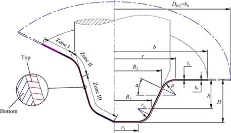
Fig. 2 Forming area during hydrodynamic deep drawing process
In this work, HDDRP of double layered sheets is theoretically analyzed using Barlat-Lian quadratic yield criterion and normal anisotropy condition by plane strain tensile instability criterion. This criterion was proved to give reliable results [7]. Usually for spherical, conical and cylindrical shells under pressure, there are two plastic instability conditions: 1) instability under maximum force, and 2) Instability under maximum pressure. During HDDRP, force is a function of internal pressure, thus the instability under pressure is discussed here. Barlat-Lian non-quadratic anisotropic yield criterion is expressed based on principal stresses as follows [10]:
 (1)
(1)
 and
and  (2)
(2)
 and
and  (3)
(3)
where k1 and k2 are coefficients of Barlat-Lian yield criterion, a is an exponent related to the yield surface shape, and R0 and R90 are anisotropy coefficients. Combining Eqs. (1), (2) and (3), the yield criterion can be written as Eq. (4) for planar isotropy (u=1):
 (4)
(4)
where
 (5)
(5)
where R is the average anisotropy parameter. Associated flow rule is expressed as
 (6)
(6)
Combining Eq. (4) (with a=2) and Eq. (6), one obtains

 (7)
(7)
2.1 Zone I
A radial element for analysis of Zone I is shown in Fig. 3. Tangential and radial directions are considered as principal directions. Top and bottom layers are indicated by indices ��t�� and ��b��, respectively.

Fig. 3 Double layered element at flange area (Zone I)
Polar equilibrium equation at peripheral edge is written as
 (8)
(8)
where Ff is the friction force on the rim. Since the forming media is oil in this process and full lubrication exists, Coulomb��s friction model is assumed in this model. Other frictional models are also applicable [11,12].
Since the radial and tangential stresses in Zone I are tensile and compressive, respectively, Eq. (9) can be written from Eq. (7).
 (9)
(9)
 (10)
(10)
The effective stress from Eq. (4) can be written as
 (11)
(11)
The effective strain component can be obtained by using Eqs. (1), (7) and (11) based on radial and tangential strain increments.
 (12)
(12)
Assuming volume constancy regardless of flange thinning, it can be written as
d��r=-d���� (13)
 (14)
(14)
Radial strain at any point is obtained by Eq. (15).
 (15)
(15)
Thus, the effective strain in terms of the radial strain is obtained as follows:
 (16)
(16)
 (17)
(17)
Power-law hardening material is assumed as Eq. (17). So, Eqs. (10), (14) and (16) give
 (18)
(18)
Equation (19) is obtained by applying the radial equilibrium equation.
(��r+d��r)(r+dr)d��tt-��rrd��tt-����d��drtt+(��tp-��t)dA1=0 (19)
Area of the element is given by
 (20)
(20)
By substituting and simplifying Eq. (20) into Eq. (19), one can obtain
 (21)
(21)
Similarly, for the bottom layer:
 (22)
(22)
Combining Eqs. (21) and (22), one can write

 (23)
(23)
On the other hand, total force on the sheet is equal to the sum of the forces exerted on the rim of both layers. Therefore,
Fc=Ft+Fb����rctc=��rttt+��rbtb (24)
tc=tt+tb (25)
By substituting Eqs. (24), (25) and the coefficient of friction  into Eq. (23), one can obtain
 (26)
(26)
According to Eq. (18), one can obtain

 (27)
(27)
Since the flange gap at blank holder region is constant, the variation of sheet thickness is ignored (d(tc=0)), so,
d(tc��rc)=tcd��rc (28)
So, the radial stress of the double layered sheet at Zone I will be

 (29)
(29)
(R2+��cos��)��r��b (30)
 (31)
(31)
To obtain analytical relations, it is essential to determine the relationship between the initial and current positions. For this purpose, the geometric relations for Zones I and II are calculated. The relationship between the initial blank position and the current flange position at any moment in Zone I is computed according to Fig. 2 assuming volume constancy during the deformation:


 (32)
(32)
So, at each moment, the relationship between the initial radius and outer radius of the flange at Zone II is


 (33)
(33)
According to Fig. 2, R2 is calculated based on the geometric parameters:
R2=R1+[h-(��+rp)(1-sin��)]tan �� (34)
2.2 Zone II
The process analysis is continued with respect to an element in zone II shown in Fig. 4(a).

Fig. 4 A double layered element in Zone II (a) and schematic diagram of Zone II (b)
In this area, the equilibrium equations are as follows:
 (35)
(35)
 (36)
(36)
Similar to the flange area, the shear stresses are the same (��t=��b). Thus, the radial stress in a double layered sheet is as follows:
 (37)
(37)

 (38)
(38)
Considering the stress continuity at the boundary of Zones I and II, constant of integration is obtained:
 (39)
(39)
Strain in a double layered sheet in Zone II is calculated by
 (40)
(40)
With respect to the boundary conditions, the radial stress in Zone II will be

 (41)
(41)
According to Fig. 2, assuming volume constancy during the deformation, the relationship between the initial position of blank and the current position of flange in Zone II is calculated from the following equation:


 (42)
(42)
��=cos-1[(R2+��cos��-r(II))/��], (R2(II)2<��cos ��) (43)
Considering equilibrium of forces along the z-axis in Fig. 4(b), the relationship between the curvature radius and radial stress at this zone is defined by
 (44)
(44)
2.3 Critical rupture pressure
In this process, plastic instability under high pressure occurs on one of the layers at the border of Zones II and III. According to Fig. 2, by writing the equilibrium equations at the border of Zones II and III for the conical cup, the force exerted on the sheet is calculated by

 (45)
(45)
Applying the condition of necking occurrence on one of the layers, the punch force reaches its maximum value. So, the derivative of Eq. (45) as a function of thickness will be zero.
 (46)
(46)
Punch and sheet make a firm contact under uniform pressure. So, the tangential strain component becomes zero and plane strain condition is established.
d����=0 (47)
Assuming volume constancy during the plastic deformation, one can obtain
d��r=-d��t (48)
According to Barlat-Lian yield criterion, the tangential strain is equal to
 (49)
(49)
The ratios of tangential stress to longitudinal stress on each layer are assumed as follows:
 ,
, (50)
(50)
With respect to the plane strain condition in Barlat-Lian yield criterion and Eq. (7), one can obtain
 (51)
(51)
And after simplification and differentiation, one can obtain
 (52)
(52)
The effect of fluid pressure on each layer is different based on material, thicknesses and arrangement of each constituent layer. According to Barlat-Lian yield criterion, the equivalent strain in plane strain condition is written as
 (53)
(53)
Now, assuming the necking occurrence in the upper layer and using Eqs. (46), (52) and (53), the following equation could be the ratio of equivalent stress to strain.
 (54)
(54)
Using the strain hardening behavior of the upper layer ( and Eq. (54), the effective strain in the top layer is obtained under instability conditions.
 (55)
(55)
With power law hardening rule and Eq. (54), the critical effective stress for the upper layer is obtained.
 (56)
(56)
Thus, the longitudinal stress ��z at point z=h-��(1-sin��) will be

 (57)
(57)
Similarly, the critical effective stress for the bottom layer based on premature rupture of the upper layer is obtained.

 (58)
(58)
By combining both layers, the longitudinal stress of a bilayer sheet is obtained by

 (59)
(59)
St and Sb are defined as the thickness ratios in double layered sheet.
St=tt/tc, Sb=tb/tc (60)
Using the assumption of instability in the upper layer, the critical axial stress will be obtained as a function of mechanical properties of constituent layers.

 (61)
(61)
Due to the continuity of stress at the border of Zones II and III under instability conditions, the critical fluid pressure and the curvature radius are determined with equalizing the stresses of Zones II and III at point z=h-��(1-sin��):


 (62)
(62)
So, using Eqs. (44) and (61), one can obtain

 (63)
(63)
Pi and ��i are the critical pressure and the curvature radius, respectively, calculated by numerical methods. Combining Eq. (62) with Eq. (63), the critical fluid pressure will be obtained assuming the instability in the top layer. Similarly, assuming the instability in the bottom layer, the critical axial stress is obtained as a function of both layers properties and the critical fluid pressure at the same point of instability. In this research, Newton��s method is used to solve these equations in Matlab software. A two solution set is obtained for the critical pressure on the basis of premature rupture of the top or bottom layer. The lower value is determined as the safe fluid pressure. The flow chart of solution procedure is presented in Fig. 5.

Fig. 5 Flow chart of solution procedure
3 Experimental validation
To verify and validate the theoretical model, experiments are performed on aluminium/steel double layered sheets with Al1050 as the top layer (0.4 mm thick) and St13 as the bottom layer (0.7 mm thick). Their mechanical properties are given in Table 1. Polyurethane adhesive is used for preparation of bilayer sheets. A HDDRP system consists of a hydraulic press, punch, pressure chamber, blank holder, hydraulic pump, pressure relief valve, one-way check valve for connection to the hydraulic pump, pressure gauge and other related hydraulic fittings. Figure 6 shows a typical pressure loading path used during the forming process. Path OA indicates the pre-bulging pressure applied before downward movement of the punch. The amount of this pressure is selected as 0.2 MPa [13]. Path BC is the constant pressure which is equal to the maximum forming pressure adjusted on the hydraulic pressure relief valve. Pressure relief valve is set to open when the pressure reaches the critical pressure and discharges the fluid to keep the pressure at the predetermined level.
Table 1 Mechanical properties of aluminium and steel layers


Fig. 6 Typical pressure loading path used in experiments
For better comparison, dimensionless critical pressure is used in the charts by dividing it by the combined strength coefficient (Kc). Kc for Al/St sheet is 275 MPa by standard ASTM tensile test on double layered sample. Figure 7 shows the critical rupture pressures for double layered Al/St sheet in HDDRP of conical cups obtained by the new proposed theoretical model and experimental tests. It is shown that by increasing the height ratio, the amount of critical rupture pressure increases, expanding the forming area to an upper limit. This phenomenon is mainly because of the enhancement of material strength due to work hardening during the forming process. A relatively good conformity is observed between theoretical and experimental results. The difference is due to the simplifying theoretical assumptions and real frictional conditions. This error is acceptable in a complex forming process such as HDDRP. The proposed model is then validated.

Fig. 7 Comparison of theoretical and experimental critical rupture pressures
Figure 8 shows two completely formed parts along with their finite element simulations. Part A represents layer arrangement of Al/St, and Part B represents layer arrangement of St/Al.

Fig. 8 Samples produced by HDDRP process
4 Results and discussion
4.1 Effect of friction
Frictional condition at flange area plays an important role in the flow of material during the forming of conical cups. In this process, the initial blank is in contact with blank holder from the top and with pressurized fluid from the bottom and peripheral side. On the other hand, radial pressure on the blank sides contrary to the friction direction improves the flow of material into the die cavity. According to the theoretical results, increase of coefficient of friction (COF) at this area is an important factor in reduction of critical pressure. Lower critical pressures increase the failure probability. Figure 9 shows that by use of 0.15 instead of 0.05 as the COF, critical pressure decreases from 300 MPa to 80 MPa at the end of the process.
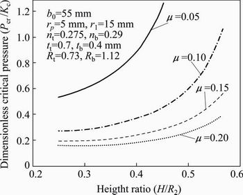
Fig. 9 Effect of friction on critical rupture pressure of double layered Al1050/St13 sheet
4.2 Effect of drawing ratio
Drawing ratio for conical parts is defined as the ratio of initial blank diameter to the least diameter of the cone part (flat bottom) [14]:
 (64)
(64)
The effect of strain rate on critical rupture pressure is shown in Fig. 10. With increasing the drawing ratio,the critical pressure will decrease dramatically. Particularly at drawing ratios higher than 4, the allowable pressure range is much lower. Therefore, to produce parts with higher RD, the forming pressure has a limited range in order to avoid instability and rupture. It follows that the production of a non-defective part with high drawing ratio has a particular complexity with need of precise determination and control of pressure loading path.

Fig. 10 Effect of drawing ratio on critical rupture pressure of double layered Al1050/St13 sheet
4.3 Effect of punch tip radius
According to the analytical model, punch tip radius is another critical factor in determining the rupture pressure of double-layered components. In Fig. 11, the critical pressure curve for HDDRP of conical double layered cups at different radii is shown. Results show that the critical rupture pressure decreases due to the decrease of punch tip radius. This indicates that the geometry of the conical punch may highly affect the occurrence of rupture. According to Fig. 11, this effect is increased significantly at final forming stages. The difference of critical dimensionless pressures for two punches with 5 mm and 10 mm tip radii is about 0.1 at the beginning of forming process while it is increased to more than 0.5 at the end of the forming process.

Fig. 11 Effect of punch tip radius on critical rupture pressure of double layered Al1050/St13 sheet
4.4 Effect of anisotropy
Materials with higher anisotropy have better formability and higher critical rupture pressure. The effect of anisotropy on the critical rupture pressure is shown in Fig. 12.
4.5 Effect of thickness
Different double layered sheets are compared with respect to their constituent layer thicknesses. It is shown in Fig. 13 that the amount of rupture pressure increases dramatically with increasing the thickness of each layer. In Al1050/St13 case, with increasing the thickness of each layer from 0.3 to 0.7 mm, the critical pressure range increases from 30-55 MPa to 137-300 MPa.
4.6 Effect of strain hardening exponent
Figure 14 shows that with the increase of strain hardening exponent, critical pressure increases anddelays the rupture occurrence. It can be seen that with plastic deformation of layers at final stages of forming, the effect of work hardening on total formability will fade.

Fig. 12 Effect of anisotropy on critical rupture pressure
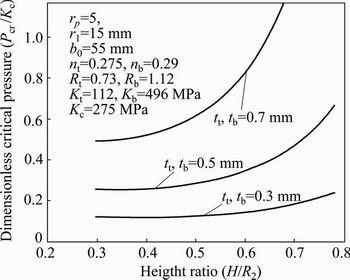
Fig. 13 Effect of layer thickness on critical pressure

Fig. 14 Effect of strain hardening exponent on critical rupture pressure
5 Conclusions
1) Increase of COF (insufficient lubrication) at flange area reduces the critical pressure significantly, causing premature rupture. In the present case, a change of COF from 0.05 to 0.15 decreases the critical pressure from 135-300 MPa to 55-80 MPa during the forming process.
2) Higher drawing ratios result in a limited range of critical pressure. Certain determination and control of pressure loading is required for drawing ratios higher than 4 to produce non-defective parts.
3) Higher anisotropy of layers significantly improves the formability. The critical rupture pressure increases about twice when doubling the anisotropy of each constituent layer.
4) The effect of punch tip radius is intensified approaching the final stages of forming process. Smaller radius increases the chance of premature rupture. Increase of punch tip radius from 5 to 10 mm increases the difference of dimensionless critical pressure from 0.1 at the beginning of the process to more than 0.5 at the end of forming.
5) Safe forming range is too much wider for thicker sheets. With the increase of the thickness of each layer from 0.3 to 0.7 mm, safe pressure range increases from 30-55 MPa to 137-300 MPa. Hence, the precise determination of pressure range is essential in forming of thin sheets.
6) Strain hardening exponent affects the critical rupture pressure. At final forming stage, the effect of strain hardening exponent decreases due to the work hardening of the double layered sheet.
References
[1] XU Hai-bin, SEYEDKASHI S M H, KIM S Y, MOON Y H. Analytical prediction of forming pressure for three-layered tube hydroforming [J]. Proceedings of the Institution of Mechanical Engineers, Part B, Journal of Engineering Manufacture, 2015, DOI: 10.1177/0954405414539489.
[2] SEYEDKASHI S M H, PANAHIZADEH V, XU H B, KIM S Y, MOON Y H. Process analysis of two-layered tube hydroforming with analytical and experimental verification [J]. Journal of Mechanical Science and Technology, 2013, 27(1): 169-175.
[3] LANG Li-hui, DANCKERT J. Investigation into hydrodynamic deep drawing assisted by radial pressure. Part I: Experimental observations of the forming process of aluminum alloy [J]. Journal of Materials Processing Technology, 2004, 148: 119-131.
[4] LANG Li-hui, DANCKERT J, NIELSEN K B. Investigation into hydrodynamic deep drawing assisted by radial pressure. Part II: Numerical analysis of the drawing mechanism and the process parameters [J]. Journal of Materials Processing Technology, 2005, 166: 150-161.
[5] LANG Li-hui, DANCKERT J, NIELSEN K B. Multi-layer sheet hydroforming: Experimental and numerical investigation into the very thin layer in the middle [J]. Journal of Materials Processing Technology, 2005, 170: 524-535.
[6] MOROVVATI M R, DARIANI B M, ARDAKANI M H A. A theoretical, numerical and experimental investigation of plastic wrinkling of circular two-layer sheet metal in the deep drawing [J]. Journal of Materials Processing Technology, 2010, 210(13): 1738-1747.
[7] BAGHERZADEH S, MOLLAEI-DARIANI B, MALEKZADEH K. Theoretical study on hydro-mechanical deep drawing process of bimetallic sheets and experimental observations [J]. Journal of Materials Processing Technology, 2012, 212(9): 1840-1849.
[8] MOHAMMADI S V, PARSA M H, AGHCHAI A J. Effect of the thickness distribution and setting condition on springback in multi-layer sheet bending [J]. International Journal of Engineering Science and Technology, 2011, 3(4): 225-235.
[9] SERROR M H. Analytical study for deformability of laminated sheet metal [J]. Journal of Advanced Research, 2013, 4(1): 83-92.
[10] BARLAT F, LIAN K. Plastic behavior and stretchability of sheet metals. Part I: A yield function for orthotropic sheets under plane stress conditions [J]. International Journal of Plasticity, 1989, 5(1): 51-66.
[11] HASSAN M A, HINO K, TAKAKURA N, YAMAGUCHI K. Friction aided deep drawing of sheet metals using polyurethane ring and auxiliary metal punch. Part 2: Analysis of the drawing mechanism and process parameters [J]. International Journal of Machine Tools & Manufacture, 2002, 42: 633-642.
[12] HASSAN M A, SUENAGA R, TAKAKURA N, YAMAGUCHI K. A novel process on friction aided deep drawing using tapered blank holder divided into four segments [J]. Journal of Materials Processing Technology, 2005, 159: 418-425.
[13] GORJI A, HASHEMI H A, JOOYBARI M B, NOUROUZI S, HOSSEINIPOUR S J. Investigation of hydrodynamic deep drawing for conical�Ccylindrical cups [J]. International Journal of Advanced Manufacturing Technology, 2011, 56(9-12): 915-927.
[14] KHANDEPARKAR T, LIEWALD M. Hydromechanical deep drawing of cups with stepped geometries [J]. Journal of Materials Processing Technology, 2008, 202(1-3): 246-254.
˫���α���ˮ������
Alireza JALIL1, Mohammad HOSEINPOUR GOLLO1,
M. Morad SHEIKHI1, S. M. Hossein SEYEDKASHI2
1. Faculty of Mechanical Engineering, Shahid Rajaee Teacher Training University, Tehran 16785-136, Iran;
2. School of Mechanical Engineering, University of Birjand, Birjand 97175-376, Iran
ժ Ҫ������ѹ������ˮ��������һ���Ƚ��İ�ij��μ�������������ȸߣ����������úͳߴ羫�ȸߵ��ŵ㡣����������У��������߶��ܵ�ˮ����ѹ������˱��ξ��ȣ�ʧЧ�����Լ�С���봫ͳ���ι�����ȣ�ˮ���������������׳��θ�����״�Ķ���ġ������ǰ�ij��ι�������Ҫ�IJ������ʧЧ��ʽ������Ԥ���ȷ�����Ż����ʹ��ղ���������Ҫ���á���������ģ�ͼ����˾���ѹ������ˮ����������˫���α����ٽ�����ѹ���������������������ͷ�뾶������ȡ�Ħ����������ĺ�ȺͲ������ܵȶ��ٽ�����ѹ����Ӱ�졣������ģ��������Ԫģ����бȽϣ�����Al1050/St13 ˫�����Ͻ���������֤�������������������������һ�¡�
�ؼ��ʣ�ˮ������������ѹ����˫��壻�α����ٽ�ѹ��
(Edited by Yun-bin HE)
Corresponding author: Mohammad HOSEINPOUR GOLLO; Tel: +98-21-22970052;E-mail: m.hoseinpour@srttu.edu
DOI: 10.1016/S1003-6326(16)64109-2
