J. Cent. South Univ. Technol. (2008) 15(s1): 391-396
DOI: 10.1007/s11771-008-386-z

Numerical simulation of creep characteristics of soft roadway with bolt-grouting support
WANG Lian-guo(王连国)1, 2, LI Hai-liang(李海亮)1, 2, ZHANG Jian(张 健)1, 2
(1. State Key Laboratory for Geomechanics and Deep Underground Engineering,
China University of Mining and Technology, Xuzhou 221008, China;
2. College of Sciences, China University of Mining and Technology, Xuzhou 221008, China)
Abstract: Based on the engineering background of a soft rock roadway in Qinan Coal Mine 82 Area, Huaibei Mining Group, three creep models with different support patterns in soft rock roadway were established by using geotechnical software of FLAC2D. According to the calculation results of different models, the change law of mechanical properties with the time of bolt-grouting support structure was obtained. Furthermore, for the test bolt-grouting support roadway, the deformation law of surrounding rock got by underground industrial experiment and field observation accords with the creep law got by numerical calculation. The results of numerical calculation and field observation show that, compared with other supports, the creep of bolt-grouting support roadway enters the steady-state creep stage from tertiary creep stage ahead, the deformations of roof, floor and two sides are decreased greatly, the plastically deforming area in surrounding rock is reduced obviously, and the distribution ranges of maximum and minimum principal stress are shrank obviously. All those fully show that the bolt-grouting support has its remarkable advantages in controlling surrounding rock creep and improving the whole strength of surrounding rock and self-bearing capacity.
Key words: soft rock; bolt-grouting support; creep; numerical simulation; engineering practice
1 Introduction
Support in soft rock roadways is a puzzle in coal mine work safety. To solve this problem, many scholars have done a lot of researches, and have proposed the joint support theory, the support theory of broken rock zone, the support theory of engineering geology, the support theory of primary-secondary bearing area, and so on. At present, support patterns used in soft rock are metal stent, bolt-shotcrete support, anchor net unit support, cable support and bolt-grouting support. Thereinto, the active support pattern, the purpose of which is to improve the whole strength of surrounding rock and self-bearing capacity, is widely praised, especially, the bolt-grouting support has now become an effective way to resolve the problem of support in soft rock roadways.
In recent years, the rock rheologic theory developed rapidly, and many important studies are focused on a single rock’s creep characteristics[1-3]. But, the study on the creep characteristics of the structure with bolt-grouting support is relatively less. In this work, based on the engineering background of a soft rock roadway in Qinan Coal Mine 82 Area of Huaibei Mining Group, the creep characteristics of the bolt-grouting support structure are studied by using numerical simulation analysis.
2 Engineering situation
The 5th middle yard of 82 mining area is in the southwest of Qinan Coal Mine, and at the middle and lower part of 82 mining area. The roadway’s elevation is about -521.4 m to -514.6 m, and below the 72 coal floor, within the range of 30-50 m. The main of rock lithology is fine sandstone and mudstone, with thin siltstone and sandstone and partial crack developed medium sandstone, and through a layer of Al mudstone. The pitch angle is 6?-10?, with an average of 7?. The cross section of the yard is a semicircle arch, the net width is 3.4 m, and the net height is 3.2 m.
3 Establishment of numerical model
3.1 Selection of software
The geotechnical software of FLAC2D (Fast
Lagrangian Analysis of Continua) is selected.
FLAC[4] includes lining, pile, shell, beam, bolt, cable, and other computing elements for support material in coal mine roadway. So, it can simulate various of support patterns accurately and expediently. In addition, FLAC process has six models for the simulation of creep behavior of the support material. In this work, the burger-creep viscoplastic model is selected.
3.2 Principles of modeling
To obtain the correct and reasonable simulation result, the model must be established correctly. To ensure the model can reflect actual project reasonably, modeling should obey the following principles[5-9]:
1) Modeling should base on the actual project, and reflect the major mechanical problems.
2) In the process of modeling, all factors that affect the results should be analyzed, and then, the main factors should be taken into account, and the secondary factors should be integrated or omitted reasonably.
3) Roadway support is a semi-infinite problem, so the model should relieve the boundary constraint effect on stress distribution of the surrounding rock as much as possible. Therefore, the model should be large enough to relieve the boundary constraint effect.
3.3 Model and parameters
In order to describe the creep characteristics of bolt- grouting supporting structure and show the characteristics of bolt-grouting support further, three creep models are calculated, and the support patterns are non-support, anchor bolt-shotcrete unit support and anchor bolt-grouting unit support respectively.
Model Ⅰ: the non-support model.
Model Ⅱ: the anchor bolt-shotcrete unit support model. The bolt is high strength screw-thread steel bolt of d 20 mm×2000 mm, and the space dimensions are 700 mm×700 mm. The size of cable is d 15.24 mm× 6000 mm, and is driven into the roof in 45?. The shotcrete layer is C20 concrete with the thickness of 100 mm.
Model Ⅲ: the anchor bolt-grouting unit support model. The grouting bolt is made of seamless steel tube. The size is d 22 mm× 2 050 mm with wall thickness of 4 mm, the end is twisted anchorage section, and the grout diffusion radius is 1.5 m.
The dimensions of models are 60 m×60 m. The lithologies and mechanical parameters are listed in Tables 1 and 2.
On the upper boundary, the applied stress is 11.4 MPa, the side pressure coefficient λ=1. The left and right boundaries are horizontal constraints, and the lower boundary is vertical constraint.
Table 1 Mechanical parameters of surrounding rock and support material
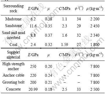
Table 2 Rheological parameters of rocks
4 Simulation and analysis
The creep characteristics of surrounding rock in different support patterns were studied comprehensively, including the relation between rock surface displacement and time, the relation between plastic zone and time, and the minimum and maximum principal stress.
4.1 Results and analysis of models
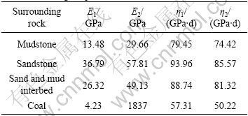
Within 150 d, the relationship between rock surface displacement and time is shown in Fig.1, the relation between plastic depth and time is shown in Fig.2, and the minimum and maximum principal stresses are shown in Fig.3 and Fig.4. In Figs.3-4, Us denotes the rock surface displacement; t denotes the time; and Ps denotes the plastic depth.
1) The rock surface displacement rates are increased continuously in the first 15 d for model Ⅰ, 10 d for model Ⅱ, 7 d for model Ⅲ, and the rates of roof, floor and side reach the average of 4.73, 5.24 and 5.35 mm/d for model Ⅰ, 1.66, 4.06 and 3.33 mm/d for model Ⅱ, 1.35, 2.35 and 2.32 mm/d for model Ⅲ. Since then, the deformation enters the first stage―tertiary creep. In this stage, the displacement rates of roof, floor and side are
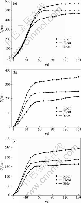
Fig.1 Relationship between rock surface displacement and time: (a) Model Ⅰ; (b) Model Ⅱ; (c) Model Ⅲ
increased to the average rates of 9.78, 10.81 and 10.43 mm/d for model Ⅰ, 4.25, 7.41 and 5.59 mm/d for model Ⅱ, 3.45, 5.62 and 4.14 mm/d for model Ⅲ. The displacement decreases rapidly, and enters the second stage―steady-state creep in the 60th day for model Ⅰ, in the 50th day for model Ⅱ, in the 45th day for model Ⅲ. After 150 d, the ultimate displacements of roof, floor and side are 489.66, 566.62 and 499.58 mm for model Ⅰ, 213.17, 350.48 and 248.66 mm for model Ⅱ, 162.29, 245.15 and 186.92 mm for model Ⅲ.
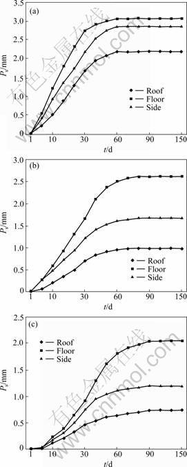
Fig.2 Relationship between plastic depth and time: (a) Model Ⅰ; (b) Model Ⅱ; (c) Model Ⅲ
2) The plastic zones are expanded gradually, the rate of floor is the largest, followed by two sides, and the least is the roof. The plastic zone reaches the maximum in the 60th day for model Ⅰ, in the 75th day for model Ⅱ, in the 90th day for model Ⅲ. After 150 d, the plastic depth of roof, floor and side are 2.176, 3.06 and 2.856 m for model Ⅰ, 0.987, 2.611 and 1.677 m for model Ⅱ, 0.731, 2.036 and 1.194 m for model Ⅲ.
3) The distribution range of maximum and minimum principal stress are 3.85-6.27 m and 4.31-5.75 m for model Ⅰ, 1.33-4.06 m and 1.01-3.63 m for model
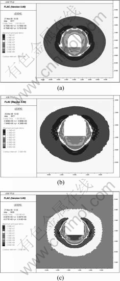
Fig.3 Maximum principal stress: (a) Model Ⅰ; (b) Model Ⅱ; (c) Model Ⅲ
Ⅱ, 1.28-3.82 m and 0.62-3.43 m for model Ⅲ. There are stress concentration phenomena at base angles, and the concentration factor of maximum principal stress is 1.53 for model Ⅰ, 1.58 for model Ⅱ, 1.77 for model Ⅲ.
4.2 Comparative analysis of models
1) Compared with the non-support roadway and the anchor bolt-shotcrete unit support roadway, the anchor bolt-grouting unit support roadway is 8 d and 3 d ahead to enter tertiary creep stage, and 15 d and 5 d ahead to enter steady-state creep stage. Before entering tertiary creep stage, the displacement rates of roof, floor and side are decreased by 71.46%, 55.15%, 56.64% and 18.68%, 42.12%, 30.33%, and after that, the rates are decreased by 65.05%, 48.01%, 60.31% and 18.82%, 24.16%, 25.94%. After 150 d, the displacement of roof, floor and side are decreased by 66.86%, 56.74%, 62.59% and 23.87%, 30.05%, 24.83%, respectively.
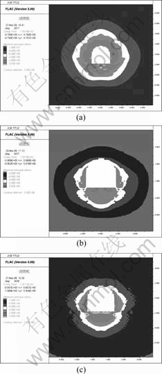
Fig.4 Minimum principal stress: (a) Model Ⅰ; (b) Model Ⅱ; (c) Model Ⅲ
2) Compared with the non-support roadway and the anchor bolt-shotcrete unit support roadway, the anchor bolt-grouting unit support roadway is 30 d and 15 d delay to reach the maximum of plastic zone, and the maximum plastic zone of roof, floor and side are decreased by 66.41%, 33.46%, 58.19% and 25.94%, 22.02%, 28.80%. It shows that the anchor bolt-grouting unit support controls the expansion of plastic zone effectively, especially for the creep of roof and side.
3) For the anchor bolt-grouting unit support roadway, compared with the non-support roadway and the anchor bolt-shotcrete unit support roadway, the distribution range of maximum principal stress is decreased by 39.08%-66.75% and 3.76%-5.91%, the distribution range of minimum principal stress is decreased by 40.35%-85.62% and 5.51%-38.61%, and the maximum principal stress concentration factor is increased by 15.69% and 12.03%.
5 Engineering practice
In the test anchor bolt-grouting unit support roadway of 82 Area 5 Middle Yard, Qinan Coal Mine, there are three observation points for rock surface displacement. Through field observation, the creep characteristics of the bolt-grouting support structure are further discussed.
The observation results are shown in Fig.5.
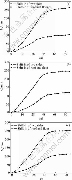
Fig.5 Observation results: (a) No.1 observation point; (b) No.2 observation point; (c) No.3 observation point
The observation results show that the creep process of the bolt-grouting support structure is fully consistent with the numerical simulation results.
The creep enter the steady-state creep stage in 50 d, and the convergence between roof and floor is obviously larger than the convergence between two sides, as listed in Table 3.
Table 3 Convergence of surrounding rock
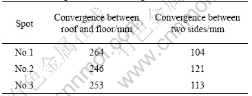
From the viewpoint of deformation, the convergence between roof and floor is less than 270 mm, and the convergence between two sides is less than 125 mm, that is to say, the bolt-grouting support controls deformation effectively, and the bolt-grouting support maintains the stability of roadway preferability.
6 Conclusions
1) Based on the engineering background of a soft rock roadway in Qinan Coal Mine 82 Area, Huaibei Mining Group, three creep models with different support patterns in soft rock roadway are simulated.
2) After 7 d of accelerated deformation stage, the deformation of bolt-grouting support roadway enters the tertiary creep stage, and then enters the steady-state creep stage in 45 d. For the bolt-grouting support roadway, compared with the anchor bolt-shotcrete unit support roadway, during the tertiary creep stage, the displacement rates of roof, floor and side are decreased by 18.67%, 42.12%, 30.33%, and the ultimate displacement are decreased by 23.87%, 30.05%, 24.83%.
3) The plastic zone of bolt-grouting support roadway extends to the depth of rock with time going, and reaches the maximum in the 90th day, which is, compared with the non-support and anchor bolt-shotcrete unit support, delayed by 30 d and 15 d. For the bolt-grouting support roadway, compared with anchor bolt-shotcrete unit support, the maximum of plastic zone of roof, floor and side are decreased by 25.94%, 22.02%, 28.80%.
4) Compared with non-support and anchor bolt- shotcrete unit support, the distribution range of principal stress of the bolt-grouting support roadway is decreased greatly, and the stress concentration factor is significantly increased.
5) The results of numerical calculation and field observation show that the bolt-grouting support structure ends the tertiary creep stage and enters the steady-state creep stage in 45 to 50 d.
6) On the basis of the above analyses, the bolt-grouting support can control deformation reasonably and effectively, improve the strength of rock fundamentally, extend the service life of roadway, and maintain the stability of roadway preferability.
References
[1] WANG Hong-wei, WANG Xi-liang. Research on rheological characteristics of rock in the weak coal-bearing strata [J]. Underground Space, 2001, 21(5): 361-364. (in Chinese)
[2] ZHU Zhen-de, WANG Yu-shu. Study on impact of the creep on the stability of roadway [J]. Mechanics and Engineering, 1998(20): 26-29. (in Chinese)
[3] CUI Xi-hai, FU Zhi-liang. Experimental study on rheology properties and long-term strength of rocks [J]. Chinese Journal of Rock Mechanics and Engineering, 2006, 25(5): 1021-1024. (in Chinese)
[4] LIU Bo, HAN Yan-hui. Principle and example of FLAC and its application guides [M]. Beijing: China Communications Press, 2005. (in Chinese)
[5] WANG Lian-guo, LI Ming-yuan. Trial study on internal grouting bolt support for coal roadway in high stress and structure zone [J]. Ground Pressure and Strata Control, 2004(1): 1-3. (in Chinese)
[6] WANG Lian-guo, MIAO Xie-xing, DONG Jian-tao. Numerical simulation of bolt-grouting support in soft roadway affected by mining [J]. Journal of Mining & Safety Engineering, 2006, 23(1): 39-42. (in Chinese)
[7] WANG Lian-guo, MIAO Xie-xing, DONG Jian-tao. Numerical simulation research of bolt-grouting support in deep soft roadway [J]. Rock and Soil Mechanics, 2005, 26(6): 983-985. (in Chinese)
[8] FAN Qing-zhong, GAO Yan-fa, CUI Xi-hai, FU Zhi-liang. Study on nonlinear creep model of soft rock [J]. Chinese Journal of Geotechnical Engineering, 2007, 29(4): 505-509. (in Chinese)
[9] WANG Yong-gang, REN Wei-zhong. Creep damage characteristics and decision of optimum support time for weak surrounding rock [J]. China Railway Science, 2007, 28(1): 51-53. (in Chinese)
(Edited by YUAN Sai-qian)
Foundation item: Project(106084) supported by the Scientific and Technological Research of the Ministry of Education; Project(BK2007701) supported by the Natural Science Foundation of Jiangsu Province, China; Project(2006CB2022010) supported by the National Basic Research Program of China and the Qing-lan Project of Jiangsu Province, China
Received date: 2008-06-25; Accepted date: 2008-08-05
Corresponding author: WANG Lian-guo; Tel: +86-516-83885205; E-mail: lgwang@cumt.edu.cn

