Interaction between transverse isotropy rock slope andsupporting structure
��Դ�ڿ������ϴ�ѧѧ��(Ӣ�İ�)2008��������1��
�������ߣ������� ������
����ҳ�룺415 - 423
Key words��rock mechanics; transverse isotropy; pre-stressed anchor cable; frame beam; finite element analysis; anchorage angle
Abstract: In order to study the interaction between transverse isotropy rock mass and supporting structure, the laboratory tests for rock sampled from the slope at expressway project were carried out, and the parameters of elasticity for transverse isotropic rock were determined by the uniaxial compression tests for rock sample with different strike of stratification plane. Then, based on the relationship of stress��stain for transverse isotropic rock mass, the analytical model was established for the interaction between transverse isotropic rock mass and frame beam with pre-stressed anchor cable. Furthermore, the conception of the best anchorage-angle in pre-stressed anchor cable was proposed. At last, the parameters of the interaction between transverse isotropy rock mass and frame beam with pre-stressed anchor cable were investigated by finite element method, and the best anchorage-angle in pre-stressed anchor cable was obtained. The rules of the influence of the directivity of stratification plane on supporting structure were determined. The results show that the analytical model and numerical method on the design of pre-stressed anchor cable with frame beam supporting for transverse isotropy rock slope are reasonable and reliable in practical engineering design.
������Ϣ��Scientific Research Fund of Central South University of Forestry and Technology, China
J. Cent. South Univ. Technol. (2008) 15(s1): 415-423
DOI: 10.1007/s11771-008-391-2
![]()
DUAN Liang-liang(������)1, FANG Li-gang(������)2
(1. College of Civil Engineering, Architecture and Mechanics,
Central South University of Forestry and Technology, Changsha 410075, China;
2. School of Architectural and Civil Engineering, Central South University, Changsha 410075, China)
Abstract: In order to study the interaction between transverse isotropy rock mass and supporting structure, the laboratory tests for rock sampled from the slope at expressway project were carried out, and the parameters of elasticity for transverse isotropic rock were determined by the uniaxial compression tests for rock sample with different strike of stratification plane. Then, based on the relationship of stress��stain for transverse isotropic rock mass, the analytical model was established for the interaction between transverse isotropic rock mass and frame beam with pre-stressed anchor cable. Furthermore, the conception of the best anchorage-angle in pre-stressed anchor cable was proposed. At last, the parameters of the interaction between transverse isotropy rock mass and frame beam with pre-stressed anchor cable were investigated by finite element method, and the best anchorage-angle in pre-stressed anchor cable was obtained. The rules of the influence of the directivity of stratification plane on supporting structure were determined. The results show that the analytical model and numerical method on the design of pre-stressed anchor cable with frame beam supporting for transverse isotropy rock slope are reasonable and reliable in practical engineering design.
Key words: rock mechanics; transverse isotropy; pre-stressed anchor cable; frame beam; finite element analysis; anchorage angle
1 Introduction
Because of the stratification, schistosity, fault or well-developed joint system in some directions within rock mass, different moduli of elasticity along the direction of stratification and the direction perpendicular to stratification exist in the rock mass, and the difference may be more than scores of times. All the directions parallel to the bedding plane, known as ��transverse directions��, have the same elasticity characteristic. This type of rock mass is called as transverse isotropy rock mass or bedded rock mass[1-2]. If it is still calculated as isotropy material, it will not be accorded with the actual condition. The transverse isotropy characteristic of rock mass makes the mechanics and numerical analyses of slope become very complicated, and has strong influence on supporting structure of the slope.
For transverse isotropy rock mass of slope, it is very important in engineering practice to search for rational and effective slope reinforcement measure. New types of anti-slide structure such as pre-stressed anchor cable with frame beam have already applied in quantity in the engineering, whose design and calculation theory research acquired some achievement[3-4]. Pre-stressed anchor cable with frame beam is a new type of anti-slide supporting and retaining structure that is combined with slope protection by the frame beam and anchor engineering. The principle includes two aspects. On one hand, it is an important part of the supporting system in which the rock mass is reinforced by pre-stressed anchor cable, the physical mechanics characteristic of the rock mass is utilized and the pre-stress is provided by grouting technique for stabilized rock mass within the slope so that enough stabilized pre-stress value is obtained. Meanwhile, under the effect of forward pressure, the friction force on slip plane of shallow layer of rock mass will increase, therefore, shear strength of the slip plane and slip resistance force of slopes will be enhanced to prevent land slide mass from unceasingly slipping along existed slip plane and make weak plane produce extrusion and combination, viz. called ��back pressure�� technique. On the other hand, under the action of the tensile force of pre-stressed anchor cable, the slope deformation is restrained by the concrete frame beam in larger range, and a reinforcement system from slope surface to slope interior is formed by available connection of the concrete frame beam and pre-stressed anchor cable, therefore, the aim of protecting the whole slope from instability is attained.
In this work, laboratory tests were conducted for rock sampled in situ to determine the transverse isotropy parameter of the rock mass, based on strength criterion of the anisotropy rock mass. The best anchorage-angle in pre-stressed anchor cable for reinforcing transverse isotropy slope was provided. And the finite element model for actual problem is simulated. Furthermore, stress distribution on rock mass transverse isotropy of slope produced by the pre-stressed anchor cable and frame beam and stress condition of the frame beam were analyzed from three points of view.
2 Theory on rock mass transverse isotropy
Generally, the constitutive equation of linear and elasticity rock material is
 (1a)
(1a)
or
eij=Cijklskl (1b)
where Cijkl is the elasticity compliance constant, eij is the strain tensor and sij is the stress tensor. In engineering, the common anisotropy rock mass material includes orthotropy and transverse isotropy. For the orthotropy material, x-y-z coordinate axis is its principal elasticity axis, in which the shear stress fails to appear in normal strain. Therefore, the number of elastic constants of this material can be simplified to nine. When xy plane is the principal elasticity axis of anisotropy, and z axis is the principal elasticity axis of isotropy, viz. transverse isotropy, the relationship between stress and stain can be shown as follows:
 (2)
(2)
where E1 is the elastic modulus for all the direction within isotropy plane (xy plane), E2 is the elastic modulus for the direction perpendicular to the isotropy plane, namely the elastic modulus of the direction of z-coordinate; n1 is Poisson ratio within the isotropy plane, n2 is the ratio of the strain in direction of isotropy plane to the strain in its normal direction caused by the normal stress of isotropy plane; G1 is shear modulus in isotropy plane, and G1=E1/[2(1+n1)], G2 is shear modulus for the direction perpendicular to the isotropy plane. The elasticity constants of anisotropy material are determined by the direction of Cartesian coordinates[5]. The theory that the elasticity constants are transformed in terms of Tensor Rule is indicated by LEKHNITSKII[6]. A kind of transverse isotropy material in x-y-z coordinate system is considered, and z axis is selected as its axis of rotation and symmetry, as shown in Fig.1. The angle of b is rotated around z axis, therefore, the elasticity compliance constant![]() in the constitutive equation corresponding to new coordinate system is determined by E1, E2, n1, n2, G2 and b. Thus, for
in the constitutive equation corresponding to new coordinate system is determined by E1, E2, n1, n2, G2 and b. Thus, for ![]() coordinate system, its elasticity constants can be determined by the following equations[7]:
coordinate system, its elasticity constants can be determined by the following equations[7]:

Fig.1 Schematic diagram of transversely isotropic material
![]()


![]()

![]()

![]()
![]() (3)
(3)
3 Determination for parameters of transverse isotropy rock
The main lithology of test sample is carbonaceous shale. The strike is SW210? and the angle of dip is 30?.
The drilling core method was adopted, in which the sample was collected according to the direction of some definite angle of![]() (
(![]() is the included angle between the stratification plane and the end face of test sample). The values of
is the included angle between the stratification plane and the end face of test sample). The values of ![]() are 0?, 30?, 60? and 90?, respectively. The samplings were divided into four groups, and there were five test samples in each group. All the test samples were sealed with wax and then transported to the laboratory for test[8].
are 0?, 30?, 60? and 90?, respectively. The samplings were divided into four groups, and there were five test samples in each group. All the test samples were sealed with wax and then transported to the laboratory for test[8].
The uniaxial compression test was made for determining the rock strength and five elasticity constants of transverse isotropy rock. The test results are shown in Table 1 and Figs.2-4.
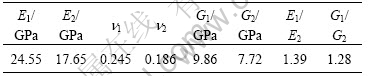
Table 1 Results of uniaxial compression test
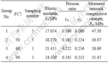
According to the above test method, five elasticity constants were obtained and listed in Table 2.
Five elasticity constants of transverse isotropy rock will meet the inequality related to thermodynamics restriction so that the strain energy of rock always keeps positive[9]:
![]()
 (4)
(4)
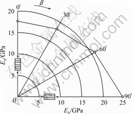
Fig.2 Variation of elastic modulus Ex in uniaxial compression test with parameter ��
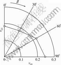
Fig.3 Variation of Poission ratio nzx in uniaxial compression test with parameter ��
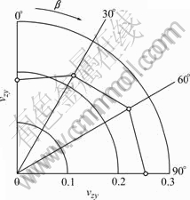
Fig.4 Variation of Poissions ratio nzy in uniaxial compression test with parameter ��
Table 2 Elastic constants determined by uniaxial compression test
4 Relationship between anchorage angle of prestressed anchor cable and structural plane
When rock mass includes a group of structural plane, its failure mode is controlled by the orientation of the structural plane. If �� is the included angle between the structural plane and the plane of maximum principal stress, normal stress �� and shear stress �� acting on this structural plane can be expressed as
 (5)
(5)
The normal stress and shear stress acting on this structural plane are dependent on angle of rotation of the structural plane (Fig.5).
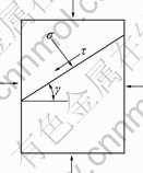
Fig.5 Unit-cell with various stresses
If the structural plane in rock mass satisfies Mohr-Coulomb strength theory, the strength expression is given by
��=cj+�� tan ��j (6)
where cj and jj are the cohesion and internal friction angle of the structural plane, respectively.
The strength theory of rock mass with single group of structural plane was proposed by KULATILAKE et al[10-12] based on Mohr-Coulomb strength theory. If
 (7)
(7)
the rock mass will be the sliding failure along the structural plane.
It may be concluded that principal stress difference (s1-s3) is dependent on the change of angle of �� of structural plane, and its minimum value will be obtained when �� is equal to 45?+��j. When angle of �� approaches to two extreme values, the structural plane will be sheared by the rock mass and the failure will occur within the rock material. When ��1�ܦáܦ�2, the rock mass will be damaged along the structural plane, in which ��1 and ��2 are given by:
![]() (8)
(8)
![]()
![]() (9)
(9)
For transverse isotropy rock mass, cohesion and internal friction angle among layers are the same, and its strength criterion is also the same as the failure criterion of the rock mass with single group of structural plane. Therefore, when ��1�ܦáܦ�2, the rock mass of slope is damaged along the stratification plane, and the angle of inclination of failure plane is the angle of inclination of the stratification plane.
When prestressed anchor cable is applied to reinforcing the rock mass, as shown in Fig.6, skid resistance P increased by reinforced force of prestressed anchor cable can be shown by
P=Pn tan ��j+Pv= Pt[sin(��+��)tan ��j+cos(��+��)] (10)
where P is the increment of skid resistance, Pt is the designed prestress value of the anchor cable, Pn is the normal component force of Pt along sliding surface, Pv is the tangential component force of Pt along sliding surface, a is the included angle between anchor cable and horizontal direction, and �� is dip angle of sliding surface, viz. dip angle of stratification plane.
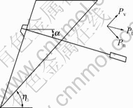
Fig.6 Schematic diagram of prestressed anchor cable
For the single anchor cable, the maximum skid resistance provided by the cable can be obtained by differentiation for Eqn.(10), viz. dP/d��=0, then Eqn.(10) becomes
 (11)
(11)
If prestressed anchor cables are installed according to the angle of ��=��j-��, the maximum skid resistance increment can be provided by prestressed force applied. In order to acquire good reinforcement effect, in slope reinforcement engineering, reinforcement effect and the cost will be comprehensively considered in accordance with specific condition, then the reasonable included angle between prestressed anchor cable and horizontal plane can be calculated. In the case of good integrity of rock mass of slope, the maximum skid resistance increment obtained from the sliding surface and the required length of the anchor cable are mainly considered, so the included angle between prestressed anchor cable and horizontal plane can be determined. If the integrity of rock mass of slope is poor, for the determination of the included angle, not only the improvement of integrity of the rock mass must be considered, but also the required skid resistance provided by the sliding surface must be taken into account[13-14].
Therefore, in view of economy aspect, for anchorage angle, the maximum skid resistance increment obtained from the sliding surface and the required length of the anchor cable must be taken into account. The length of free tension section relates to the anchorage angle, and the length of free tension section can be used for economic index. The most economic anchorage angle is based on skid resistance provided by the unit length of free tension section for the anchor cable, which can be deduced from the most economic anchorage angle, viz. ��=45?+��j/2-��.
If the angle of �� approaches to two extreme values, the anchorage angle for the maximum skid resistance of prestressed anchor cables is ��=��k-��, and the most economic anchorage angle is ��=45?+��k/2-��, in which h is the angle of dip for sliding surface.
5 Finite element analysis for interaction between transverse isotropy rock slope and prestressed anchor cable with frame beam
The main purpose of this work is to research the influence of transverse isotropy rock slope on each parameter of the prestressed anchor cable with frame beam. This model was used to simulate the practical condition of the slope site for DL06 contact section of Chongqing Dianlin Expressway Project. The model selected was the three dimensional model with the dimension of 42.5m�� 48.9 m��12 m. The prestressed anchor cables with frame beam were installed on 1-4 grade slope. The reason why this big model was selected was for simulation of prestress of the anchor cable. The form of the frame beam was decussation beam, and the schematic diagram is shown in Fig.7. Both height and width of the transom and stringer of the frame beam were 0.6 m, and the transverse space and longitudinal space were 3.6 m. The displacement of all directions for the bottom of this model was restricted, the displacement of the directions of z axis for two sides was restricted,and the displacement of the directions of x axis for pre- and post-sides was restricted. The upper side of the model was in natural state, on which any load was not applied. The design load of prestressed anchor cable was 500 kN.
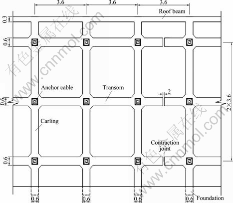
Fig.7 Elevation view of prestressed anchor cable with frame beam support (unit: m)
For exertion of the prestress of the anchor cable, cooling method was used in this work. When temperature decreases, the cable will shink and produce the tensile force for the frame beam. In the frame deformation, the tensile force will be decreased, therefore, the action form of prestressed anchor cable can be well simulated. The main problem of this whole model is the simulation of the anchor cable. Because the cable in this model was not perpendicular to the slope, first, the soil mass could be divided by coordinate plane, then, hexahedron would be formed at the middle of the soil mass, in which gird division would be carried out, next, the anchor cable elements on selected nodes were established in four sides of the hexahedron. One end of the cable was anchored within the soil mass, in which by actualized method the soil mass and the anchor cable had the common nodes, and the another end was connected with the frame beam.
In the loading mode, temperature was applied on the anchor cable to simulate prestress, and the loading criterion was
![]()
 (12)
(12)
First, the coefficient of thermal expansion was chosen; then, axial tension required was determined to calculate the temperature needed. This model assumed that the both ends of the anchor cable were completely restricted, and the prestress worked out would have the loss of prestress after the cable deformation, therefore, the force condition of the cable could be collected from the software result[15-16].
From the text information, the parameters chosen for this calculation model are listed in Tables 3 and 4, and gird division of the model element is shown in Fig.8.
In order to make the research have generalization significance, based on the practical engineering, a thorough research was carried out. The simulation included three parts.
1) When the slope was not strengthened, the influence of the change of dip angle of stratification plane for rock mass of slope on the stress distribution of the transverse isotropy slope under dead load was considered. As a result of the finite element analysis for
Table 3 Physico-mechanical parameters of calculation
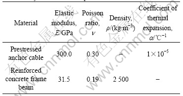
Table 4 Parameters choice of transverse isotropy rock mass
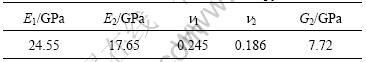
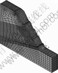
Fig.8 Finite element analysis model and grid generation
consequent slope and inverse layer slope with the dip angle of 0?, 30?, 45?, 60? and 90? for both consequent slope and inverse layer slope, when the angle between stratification plane and horizontal plane was 45?, the stress created within the slope under dead load was the maximum; when the stratification of the slope was horizontal plane, the stress was minimum.
2) After being strengthened by the prestressed anchor cable with frame beam, the anchorage angle of 20? was adopted. If dip angle of stratification plane for rock mass was changed, the influence of this change on stress distribution of the slope and force condition of the frame beam were analyzed.
As the result of the finite element analysis, when the angle between stratification plane and horizontal plane was 150?, the stress with respect to the consequent slope interior was the maximum, and the stress with respect to the slope with the vertical stratification was the minimum.
Then, a set of prestressed anchor cable with frame beam was chosen for the finite element analysis, and the analysis results are listed in Table 5.
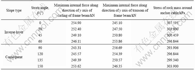
Table 5 Force analysis of frame beam with pre-stressed anchor cable
The stress change of rock in anchor position with parameter b determined by bedding surface and level is shown in Fig.9. Large internal force change in the direction of frame carling and transom with parameter b determined by bedding surface and level is shown in Fig.10.
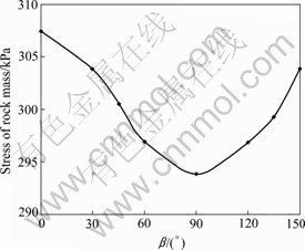
Fig.9 Stress change of rock in anchor position with parameter b determined by bedding surface and level
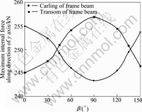
Fig.10 Large internal force change in direction of frame carling and transom with parameter b determined by bedding surface and level
From Fig. 9, Fig.10 and Table 5 it can be seen that the stress of rock mass around the anchor cable is the maximum when the stratification of the slope is horizontal plane.
The tensile force of the anchor cable was undertaken by the carling and transom. Because carling and transom of frame had the same rigidity, the tensile force was distributed by the proportion of 1?1 to the beams. From Fig.10, it can be seen that the distribution mode with the proportion of 1?1 is basically conformed for the force in the direction of the carling and transom. For consequent slope and inverse layer slope, when the angle between stratification plane and horizontal plane was 90?, the stress of the carling was the minimum, and the stress of the transom was maximum. When the angle was 0?, the stress of the carling was the maximum, and the stress of the transom was the minimum.
From Fig.11, it can be seen that the stress value of rock mass around the anchor cable is relatively large, and the stress of rock mass at the bottom of the frame beam also decreases rapidly with increasing distance from the cable position. The strain area and quantity of the rock mass are clearly shown in Fig.12. The strain at the cable position is relatively large, and the action range of the frame beam can be seen in Fig.12[17].
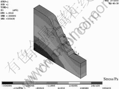
Fig.11 Map of third principal stress in 0? slope��s element node
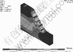
Fig.12 Map of third principal strain in 0? slope��s element node
3) If the angle between stratification plane and horizontal plane of rock mass of the slope was 30?, the influence of the change for the anchorage angle of prestressed anchor cable on transverse isotropy rock slope was analyzed.
Because of considering construction technique, the anchorage angle mostly adopts 15?-30? declination. The anchorage angle was used as 15?, 20?, 25? and 30?. A set of prestressed anchor cable with frame beam was chosen for the finite element analysis, and the analysis results are listed in Table 6.
Table 6 Effect of change in anchorage angle of pre-stressed cable on anchor cable with frame beam force
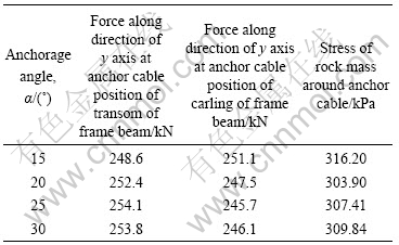
From Fig.13 and Fig.14, it can be concluded that in the case of transverse isotropy rock slope, when the anchorage angle of prestressed anchor cable is 25?, the force at anchor cable position of the transom of the frame beam is the maximum, and the force at anchor cable position of the carling of the frame beam is the minimum. When the anchorage angle is 15?, the force at anchor cable position of the transom of the frame beam is the minimum, and the force at anchor cable position of the carling of the frame beam is the maximum.
6 Conclusions
1) The theory on transverse isotropy rock slope
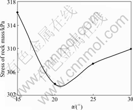
Fig.13 Variation of rock stress in anchor position with anchorage angle ��
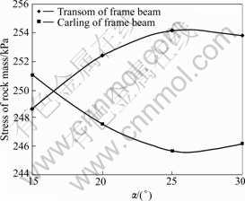
Fig.14 Curves of frame beam forces with anchorage angle ��
reinforced by the prestressed anchor cable is proposed, and how to determine the best anchorage-angle in prestressed anchor cable is analyzed. If the rock mass of slope is damaged along the stratification plane, the anchorage angle for the maximum skid resistance of prestressed anchor cables is ��=��j-��, and the most economic anchorage angle is ��=45?+��j/2-��. If the failure occurs within the rock material, the anchorage angle for the maximum skid resistance of prestressed anchor cables is ��=��k-��, and the most economic anchorage angle is ��=45?+��k/2-��.
2) From the data obtained, the characteristic of stress distribution for transverse isotropy rock slope and the force condition of the anchor cable and the frame beam were discussed by finite element analysis. Before the slope is reinforced, if the stratification plane of the slope is changed, when the angle between stratification plane and horizontal plane is 45?, the stress within the slope is the maximum. When the stratification of the slope is horizontal plane, the stress is the minimum. After the slope is reinforced, for both consequent slope and inverse layer slope, when the angle between stratification plane and horizontal plane is 90?, the stress of the carling is the minimum, and the stress of the transom is maximum; when the angle is 0?, the stress of the carling is the maximum, and the stress of the transom is minimum. If the anchorage angle is changed, when the anchorage angle of prestressed anchor cable is 25?, the force at anchor cable position of the transom of the frame beam is the maximum, and the force at anchor cable position of the carling of the frame beam is the minimum; when the anchorage angle is 15?, the force at anchor cable position of the transom of the frame beam is the minimum, the force at anchor cable position of the carling of the frame beam is the maximum.
References
[1] CHEN C S, PAN E, AMADEI B. Determination of deformability and tensile strength of anisotropic rock using brazilian tests [J]. International Journal of Rock Mechanics and Mining Sciences, 1998, 35(1): 43-61.
[2] CHEN Hong-kai, TANG Hong-mei. Visualization research on anisotropy of rock mass in rock project��Taking the slope engineering of permanent shiplocks of the Three Gorges Project as an example [J]. Journal of Chongqing Jiaotong Institute, 2000, 19(1): 92�C97. (in Chinese)
[3] XIA Xiong, ZHOU De-pei. Application for prestressed anchor rope and frame beam-on-foundation on the slope stability [J]. Subgrade Engineering, 2006(2): 68-70. (in Chinese)
[4] LIANG Yao, ZHOU De-pei, ZHAO Gang. Design of support of frame beam and prestressed anchor [J]. Chinese Journal of Rock Mechanics and Engineering, 2006, 25(2): 318-322. (in Chinese)
[5] LEKHNITSKII S G. Theory of elasticity on an anisotropic rock [M]. Moscow: Mir Publishers, 1981.
[6] AMADEI B. Importance of anisotropy when estimating and measuring in situ stresses in rock [J]. Int J Rock Mech Min Sci and Geomech Abstr, 1996, 33(3): 293-325.
[7] MILOU L. Rock mechanics [M]. LI Shi-ping, FENG Zhen-hai, transl. Beijing: China Coal Industry Publishing House, 1981. (in Chinese)
[8] KULATILAKE P H S W, WU T H, WATHUGALA.D N. Probabilistic modeling of joint orientation [J]. International Journal for Numerical and Analytical Methods in Geomechanic, 1990, 14(5): 325-350.
[9] HOOPER J A. Elastic settlement of a transversely isotropic continuum with surface loading over a polygonal region [C]// Proceedings of the Institution of Civil Engineers. London, 1985: 247-273.
[10] HUNER D F C. Deformability of joints and its relation to rock foundation settlement [J]. Candadian Center for Mineral and Energy Technology, 1978, 15(2): 239-249.
[11] ZHU Bao-long, YANG Ming, HU Hou-tian, CHEN Qiang. Testing study on internal forces for prestressed anchor cable frame in reinforced soil slope [J]. Chinese Journal of Rock Mechanics and Engineering, 2005, 24(4): 697-702. (in Chinese)
[12] DENG Tao, YANG Lin-de. Characteristics of velocity ratio of p-wave and s-wave for anisotropic rock [J]. Chinese Journal of Rock Mechanics and Engineering, 2006, 25(10): 2023-2029. (in Chinese)
[13] XU Ying-zi, TANG Hui-ming. Design of compound structure of lattice frame beam and prestressed anchor [J]. Journal of Central South Highway Engineering, 2004, 29(6): 1-4. (in Chinese)
[14] XIONG Wen-lin, HE Ze-gan, CHEN Sheng-hong. Optimum design of direction angle of prestressed anchor cable in slope reinforcement [J]. Chinese Journal of Rock Mechanics and Engineering, 2005, 24(13): 2260-2266. (in Chinese)
[15] LI Quan. Application to ANSYS in civil engineering [M]. Beijing: People��s Posts and Telecom Press, 2005. (in Chinese)
[16] HAO Wen-hua. Application insta
[17] nces of ANSYS in civil engineering [M]. Beijing: China Water Power Press, 2005. (in Chinese)
[18] HU Qi, LIN Dao-sheng, CHEN Yun-ming. Theoretical study on pile-soil homogeneous transversely isotropic model [J]. Chinese Journal of Rock Mechanics and Engineering, 2007, 26(4): 853-859. (in Chinese)
(Edited by YANG Bing)
Foundation item: Project(106023B) supported by Scientific Research Fund of Central South University of Forestry and Technology, China
Received date: 2008-06-25; Accepted date: 2008-08-05
Corresponding author: DUAN Liang-liang, Master; Tel: +86-13787251618; E-mail: chittydll@163.com

