Trans. Nonferrous Met. Soc. China 22(2012) s560-s565
Wrinkling behavior of hydro bending of carbon steel/Al-alloy bi-layered tubes
TENG Bu-gang, HU Lan, LIU Gang, YUAN Shi-jian
National Key Laboratory for Precision Hot Processing of Metals, Harbin Institute of Technology, Harbin 150001, China
Received 28 August 2012; accepted 25 October 2012
Abstract: The bi-layered tubing components provide an alternative solution to make the best use of corrosion-resistant alloys and low-alloy steels. The numerical simulation and hydro bending experiments were carried out to analyze the wrinkling behavior of carbon steel/Al-alloy bi-layered tubes with different thickness ratios and internal pressures. Two types of instabilities, namely the bifurcation instability of inner tube and the limit load instability of outer tube are noticed and examined. It is indicated that the onsets of the wrinkling of inner and outer tube are delayed with increasing the thickness ratio. The bending capacity and the stability of bi-layered tube are remarkably improved as the thickness ratio increases. The optimized range of the thickness ratio is determined by numerical simulation. It is shown that separation between two layers occurs with a lower level of internal pressure, which causes the bifurcation instability of inner tube. However, the stability of inner tube is evidently enhanced with increasing the internal pressure, resulting in larger improvements of bending limit and moment capacity. The numerical predictions are verified by the hydro bending experiments with different internal pressures. Through the analysis, the selection of the internal pressure and outer tube thickness, and the mechanisms of increasing stabilities of the inner and outer tubes are clarified. The knowledge can be transferred to other bi-layered pipes with different materials and dimensions.
Key words: bi-layered tube; bending; internal pressure; wrinkling; bifurcation instability; limit load instability
1 Introduction
The bi-layered tubing shows combined properties of heat exchange, strength and corrosion resistance that single tubes cannot provide. Industrial applications are found in compressed air supply lines, ship building and aerospace industries, and special environments [1,2]. In particular, the corrosion-resistant-alloy (CRA-lined) bi-layered pipe, which consists of a liner tube made of CRA and an outer thick-walled steel pipe, has been increasingly utilized in oil production, nuclear power plants and refining industry etc [3].
During conventional bending processes of mechanically bonded bi-layered tubes, the bending defects e.g. the wrinkling of inner layer and the departure between the two layers are often encountered. So far, there has been little discussion on the fundamental bending deformation characteristics of bi-layered tubes. MORI et al [4] performed a series of uniform bending tests to study the flattening behavior of the aluminum/ copper bi-layered tubes without the internal pressure. In order to prevent the departure between two layers, the epoxy adhesive was applied to the interface of the bi-layered tube and the tubes were hydro-bulged for 30 min in a hollow die before bending. It was shown that flattening gradually decreases when the outer aluminum proportion increases. While the thickness ratio of aluminum to copper was one, the flattening of bi-layered tube with the larger flow stress material as outer layer was greater than the reversed configuration. It was shown that smaller bending radii (��10D) could result in wrinkling and cause the inner layer to detach from the outer pipe.
Recently, however, a new hydraulic bending process of bi-layered pipes was proposed to manufacture ultra thin-walled elbows with a large diameter-to-thickness ratio (d/t>150) for piping systems of large rockets and airplanes [5]. It was shown that this process provided a solution to prevent wrinkling defects encountered in ultra thin-walled elbows manufactured by traditional bending processes, where the maximum diameter-to-thickness ratio could hardly exceed 100 [6-11]. A representative ultra thin-walled tube elbow specimen with d/t=182 was successfully obtained. This was accomplished by wrapping the inner thin-walled tube with a 10 mm carbon steel outer tube, whereby a constant and high internal pressure was supplied inside the bi-layered tube during bending. The inner tube was fitted inside the carbon steel outer pipe under high internal pressure, resulting in a tightly bonded double wall pipe, thus the stability of the ultra thin-walled tube was enhanced.
The purpose of this work is to investigate the influence of outer tube thickness and internal pressure on the bending instabilities of bi-layered tubes. The optimized outer tube thickness was determined using the finite element method, and two kinds of bending instabilities were noticed and analyzed. A series of experiments were conducted using carbon steel/Al-alloy bi-layered pipes with wall thicknesses of 3.2 mm and 1 mm. Through the analysis, the selection of the internal pressure and outer tube thickness, and the mechanisms of increasing stabilities of the inner and outer tubes are clarified. The knowledge can be transferred to other bi-layered pipes with different materials and dimensions.
2 Materials and FE model
The bi-layered tube consists of a thick-walled carbon steel outer pipe and a thin-walled aluminium alloy inner pipe with outer diameter di=63 mm, wall thickness ti=1 mm (d/t=63). The outer tube thickness to and the thickness ratio (��=to/ti) will be determined through the finite element (FE) analysis. The total length of the bi-layered tube is 660 mm, with a centre effective length of 435 mm subjected to bending. The original gap between the two layers was about 0.3 mm. The mechanical properties of the materials are listed in Table 1, which were obtained from the uniaxial tension tests. It can be seen that the aluminium alloy shows a lower plasticity with the uniform elongation of only 13.9% at room temperature.
Table 1 Mechanical properties of inner and outer tubes
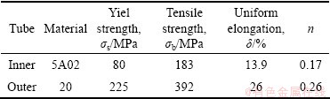
In order to improve the plasticity of aluminium alloy during bending, an annealing treatment was employed in both the finite element analysis and the experiments, to allow recrystallization of the aluminium alloy. The annealing procedure was conducted after the relative stroke of upper die (h��=h/H, where h is the current displacement and H is the total stroke) was equal to 50%. In the experiments, the annealing heat treatment was carried out at 380 ��C for 1.5 h, and air cooled to 25 ��C.
The finite element analysis code ABAQUS was employed to simulate the hydro bending of bi-layered tubes. Figure 1 shows the numerical model. The upper die and lower die were rigid shells, while the carbon steel/Al-alloy tubes were modelled separately using S4R deformable shell elements, with the element size of 2 mm. The material model used for two layers was isotropic, homogeneous, and elastic-plastic material following the Mises yield criterion. The Coulomb friction model was used for all contact surfaces with the coefficient of 0.1. A constant pressure was applied to the inner surface of the inner tube and the end caps. The expression of the yield pressure of the bi-layered tube can be derived from a previous study [12]. The yield pressures of the bi-layered tube with different thickness ratios are listed in Table 2, which could be calculated by the following equation:
 (1)
(1)
where ti is the initial thickness of inner tube, to is the initial thickness of outer tube, d is the outer diameter of inner tube, ��si is the yield strength of inner tube material and ��so is the yield strength of outer tube material.
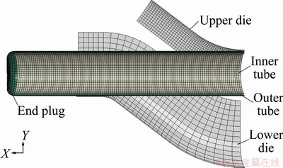
Fig. 1 FE model for bi-layered tube hydro bending
3 Effect of thickness ratio on wrinkling behavior of bi-layered tube
Numerical simulation scheme for bi-layered tube hydro bending with different thickness ratios is given in Table 2. Six thickness ratio values were adopted. The internal pressure was chosen to be the yield pressure for each bi-layered tube. It can be seen from Eq. (1) that the yield pressure increases with increasing the wall thickness of outer tube.
Table 2 Numerical simulation scheme
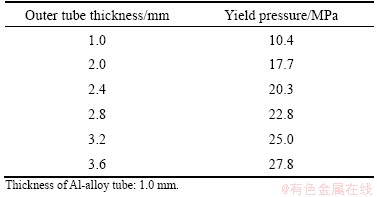
Figure 2 shows the bending results of bi-layered tube with different thickness ratios. It is shown that wrinkling (bifurcation instability) symmetrically occurs at the inside arc of both the inner and outer tubes as the thickness ratio equals one and relative stroke of upper die h��=30%. The distance from the wrinkle trough to the central section is 41 mm. It is also seen that a dent defect occurs at the centre of inside arc of inner and outer tubes as the thickness ratio equals two and h��=75%. However, the formation of the dent defect is not due to the bifurcation instability, but attributed to the bending load exceeding the bearing capacity of the bi-layered tube, which is called ��limit load instability�� [13-15]. In the same manner, the dent defect occurs at the centre of the inside arc as thickness ratio equals 2.4; however, the defect is prevented when the thickness ratio is larger than 2.8. It is indicated that the onsets of the wrinkles are delayed with increasing thickness ratio, and the bending capacity and the stability of bi-layered tube are remarkably improved as the thickness ratio increases.
It is believed that the axial compressive stress at the inside arc has a significant effect on the wrinkling behaviour. Figure 3 shows the effect of thickness ratio on the axial stress distribution of inner tube as h�� reaches 50%. It is shown from the numerical simulation that the axial compressive stress decreases with increasing thickness ratio. The maximum axial compressive stresses are 242.8, 221.7, 221.1, 219.4 and 217.1 MPa as the thickness ratio equals 1, 2, 2.4, 2.8, 3.2, and 3.6, respectively. When the maximum compressive stress is always less than the critical wrinkling stress, the inner thin-walled tube will be in the stable deformation state. This is the primary reason for the prevention of wrinkling of the inner thin-walled tube. From the above analysis, it is shown that a thicker outer tube should be adopted to prevent the instabilities and provide a stable support to the inner thin-walled tube. The bearing capacity of bi-layered tube is reinforced with increasing outer tube thickness. Correspondingly, the bending limit and stabilities of the bi-layered tube are evidently improved. From the view of material utilization, however, as long as the outer tube can prevent the inner tube from wrinkling and has enough bending capacity, and a proper out tube thickness should be adopted. In this work, the outer tube thickness of 3.2 mm is adopted in the following experiments and numerical simulation.

Fig. 2 Effect of thickness ratio on wrinkling behavior of bi-layered tube
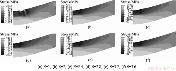
Fig. 3 Effect of thickness ratio on axial stress distribution of inner elbow tube
4 Effect of internal pressure on wrinkling behavior of bi-layered tube
Another important factor that is associated with the wrinkling behavior of bi-layered tubes is the internal pressure. In this section, the bi-layered tubes with thickness ratio of 3.2 are employed to investigate the influence of internal pressure on bending instabilities. The yield pressure of the bi-layered tube is calculated to be 25 MPa according to Eq. (1). To examine the bending behavior of bi-layered tube under lower internal pressures, five pressure values including 0, 2.5, 5, 10, 15, 20 and 25 MPa are examined.
The effect of internal pressure on the wrinkling behaviour of bi-layered tubes is shown in Fig. 4. It is shown that internal pressure can enhance the stability of both layers. Separation between two layers occurs under a lower level of internal pressure, leading to the wrinkling of the inner layer. It is seen from Fig. 4(a) that wrinkling occurs at the inside arc of inner tube without internal pressure when h�� is only 15%, whereby the wrinkling still occurs at the centre of the inside arc as the internal pressure equals 2.5 MPa and h�� reaches 55%, as shown in Fig. 4(b). When the pressure increases to 5 MPa and h�� reaches 70%, dent defects occur at the centre of the inside arc of both layers, as depicted in Fig. 4(c). This phenomenon can be interpreted that the bending capacity of the bi-layered tube cannot bear the external bending load, leading to the limit load instability. It is seen that the dent defect is lessened gradually with increasing the internal pressure, and it is prevented when the pressure exceeds 20 MPa.
The wrinkling of the inner tube is the most common defect encountered in the hydro bending process, and similarly, it is believed that the wrinkling is highly associated with the axial compressive stress at the inside arc. Figure 5 illustrates the axial stress distribution of the inner tube as h�� reaches 15%. It is shown that the maximum axial compressive stress decreases gradually with increasing the internal pressure. When the maximum axial stress exceeds the critical wrinkling stress during the bending process, the wrinkling would take place at the inside arc of the inner tube. It is seen that tiny wrinkles have occurred at the inside arc in Fig. 5(a). It should be noticed that the critical wrinkling stress is related to the bonding status of the bi-layered tubes, and a higher internal pressure contributes a tight bond state, therefore the critical wrinkling stress would increase. When the maximum compressive stress is always less than the critical wrinkling stress during the whole process, the defect is successfully prevented.

Fig. 4 Effect of internal pressure on wrinkling of bi-layered tube

Fig. 5 Effect of internal pressure on axial stress (MPa) of inner elbow tube
The numerical predictions are verified by the hydro bending experiments with different internal pressures. The experimental tooling is shown in Fig. 6, which is mounted on a hydraulic press. The inner Al-alloy tube is first inserted into the carbon steel tube, and the bi-layered tube is sealed at the end and filled with water. The internal pressure is provided by a closed-loop control pressurizing system, and in this work, the internal pressure is increased to a target value and held to be a constant.

Fig. 6 Experimental setup

Fig. 7 Hydro bending experiment results of bi-layered tubes under different pressures
Figure 7 shows confirmatory experimental results with different internal pressures. To examine the wrinkling behaviour explicitly, the bi-layered tube is cut into two halves along the bending plane. It is seen from Fig. 7(a) that the wrinkles are symmetrically located at the inside arc of inner tube. This phenomenon is as the same as the predicted result in Fig. 4(a). Similarly, the wrinkling occurs at the mid-span of the inside arc of inner arc in Fig. 7(b), which is also predicted by the numerical simulation (Fig. 4(b)). Both the numerical simulation and experiments show that the wrinkling is delayed even prevented under higher internal pressures. The section view of bi-layered tube formed under pressure of 25 MPa is shown in Fig. 7(c). It is seen that there is no tiny wrinkles at the inside arc. Figure 8 presents a sound representative bi-layered elbow hydro formed under pressure of 25 MPa, which is difficult to be manufactured by conventional bending methods.
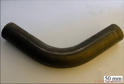
Fig. 8 Bi-layered elbow formed under pressure of 25 MPa
5 Conclusions
1) The bending capacity and the stability of bi-layered tube are evidently enhanced as the wall thickness increases. The wrinkling is prevented as the thickness ratio exceeds a critical value and the two layers show a consistent structural behavior under higher internal pressures. The maximum axial compressive stress decreases with increasing the thickness ratio.
2) Two kinds of bending instabilities are noticed and analyzed. Separation between two layers occurs under a lower level of internal pressure, leading to the wrinkling (bifurcation instability) of the inner layer. For the outer thick-walled tube, limit load instability governs the bending response and may cause section collapse in terms of dent defects. It is shown that the dent defect is lessened gradually with increasing the internal pressure, and it is prevented when the pressure exceeds 20 MPa.
3) The numerical predictions are verified by the hydro bending experiments with different internal pressures. The numerical and experimental results show a fine agreement. Both the numerical simulation and experiments show that the wrinkling is delayed even prevented with increasing the internal pressures.
References
[1] SUN X J, TAO J, GUO X Z. Bonding properties of interface in Fe/Al clad tube prepared by explosive welding [J]. Transactions of Nonferrous Metals Society of China, 2011, 21: 2175-2180.
[2] MACREA C. Manufacturing clad pipe for energy applications [J/OL]. [2002-06-17]. http://www.thefabricator.com/article/hydroforming/ one-pipe-or-twor.
[3] WANG X S, LI P N, WANG R Z. Study on hydro-forming technology of manufacturing bimetallic CRA-lined pipe [J]. Int J Mach Tools Manuf, 2005, 45: 373-378.
[4] MORI S, MANABE K, NISHIMURA H, HIROSE K. Experimental analysis of the flattening of the cross-section, the spring-back and the bending moment of clad tubes in uniform bending [J]. J Mater Process Technol, 1997, 66: 270-276.
[5] YUAN Shi-jian, HE Zhu-bin, LIU Gang, WANG Xiao-song, HAN Cong. New Developments of Hydroforming in China [J]. The Chinese Journal of Nonferrous Metals, 2011, 21(10): 2523-2533. (in Chinese)
[6] AL-QURESHI H A. Elastic-plastic analysis of tube bending [J]. Int J Mach Tools Manuf, 1999, 39: 87-104.
[7] LI H, YANG H, ZHAN M, SUN Z C, GU R J. Role of mandrel in NC precision bending process of thin-walled tube [J]. Int J Mach Tools Manuf, 2007, 47: 1164-1175.
[8] LI H, YANG H, ZHAN M, GU R J. The interactive effects of wrinkling and other defects in thin-walled tube NC bending process [J]. J Mater Process Technol, 2007, 187-188: 502-507.
[9] WELO T, WIDEROE F. Precision bending of high-quality components for volume applications [J]. Transactions of Nonferrous Metals Society of China, 2010, 20: 2100-2110.
[10] YANG H, GU R J, ZHAN M, LI H. Effect of frictions on cross section quality of thin-walled tube NC bending [J]. Transactions of Nonferrous Metals Society of China, 2006, 16: 878-886.
[11] XU J, YANG H, LI H, ZHAN M. Significance-based optimization of processing parameters for thin-walled aluminum alloy tube NC bending with small bending radius [J]. Transactions of Nonferrous Metals Society of China, 2012, 22: 147-156.
[12] HU L, TENG B G, YUAN S J. Effect of internal pressure on hydro bending of bi-layered tube [J]. Proc IMechE Part B: J Engineering Manufacture, 2012, 226(10): 1717-1726.
[13] VASILIKIS D, KARAMANOS S A. Buckling of double-wall elastic pipes under bending and external pressure [C]//Proceedings of the ASME 2011 30th International Conference on Ocean, Offshore and Arctic Engineering. Rotterdam, Netherlands. 2011: 469-478.
[14] KARAMANOS S A. Bending instabilities of elastic tubes [J]. Int J Solids Struct, 2002, 39: 2059-2085.
[15] ZHAO G Y, LIU Y L, YANG H, LU C H. Cross-sectional distortion behaviors of thin-walled rectangular tube in rotary-draw bending process [J]. Transactions of Nonferrous Metals Society of China, 2010, 20: 484-489.
��̼��/���Ͻ�˫��ܵij�Һ����������Ϊ
�����գ��� ������ �֣�Է����
��������ҵ��ѧ ���������ȼӹ����Ҽ��ص�ʵ���ң������� 150001
ժ Ҫ��˫����������ڲ���ʴ�Ͻ������̼�ֹ���ɣ������������ۺ����ܡ�ͨ������Ԫģ���ʵ���о�����㲻ͬ��ȱȺ��ڲ�Һ��ѹ���Ե�̼��/���Ͻ�˫��ܳ�Һ����������Ϊ��Ӱ�죬����˫��ܳ�Һ�������ֵ���������ʧ����ʽ�����ֲ�ʧ�Ⱥͼ�ֵ��ʧ�ȡ�����������������ź�ȱȵ����Ӷ��ӻ���˫����ȶ������ź�ȱȵ����Ӷ�������ߡ�ͨ������Ԫģ��ȷ�������ŵĺ�ȱ�ѡȡ��Χ������ѹ�ϵ�ʱ��˫����׳�����������ȱ�ݣ������ڲ����Ͻ𱡱ڹܳ��ֲַ�ʧ�ȡ�������ѹ�����ߣ��ڲ�ܿ�ʧ������������ߣ����ͼ������ӡ�ʵ������֤�˲�ͬ��ѹ�µ�����ԪԤ������ͨ�����о���ȷ����ѹ�����ܱں��ѡȡ�������õ�˫��ܳ�Һ���������ڲ㱡�ڹ�����Ļ�����
�ؼ��ʣ�˫��ܣ���������ѹ�����壻�ֲ�ʧ�ȣ���ֵ��ʧ��
(Edited by YANG Bing)
Foundation item: Projects (51175111, 50875060) supported by the National Natural Science Foundation of China
Corresponding author: YUAN Shi-jian; Tel: +86-451-86418776; E-mail: syuan@hit.edu.cn
DOI: 10.1016/S1003-6326(12)61761-0

