
Stability of electrodeposited amorphous Ni-Fe-P alloys
GAO Cheng-hui(高诚辉)
College of Mechanical Engineering, Fuzhou University, Fuzhou 350002, China
Received 28 February 2006; accepted 20 June 2006
Abstract: The stability of the electrodeposited amorphous Ni-Fe-P alloys was studied by DTA, DSC, XRD and improved four-ball wear tester in order to clear its applied scope. The results show that the element content has influence on the stability of amorphous Ni-Fe-P alloy, in which the crystallization temperature increases with Fe content, and the increase of P content delays the appearance of stable crystallization phases and recrystallization. There exist 6 exothermal reactions during heating the amorphous Ni69Fe8P23 alloy continuously. The activation energies of exothermal reactions at 248, 303, 322, 350, 376 and 442 ℃ are 131.5, 111.6, 237.8, 253.6 and 238.5 kJ/mol, respectively. The amorphous Ni60Fe22P18 alloy crystallizes when the heating temperature is beyond 250 ℃. The stable crystallization phases consist of Ni (Fe) and Ni3P-type compounds Ni3P, Fe3P, (Fe,Ni)3P. The pressure and fraction have influence on the stability of amorphous alloy. Rubbing above the critical pressure crystallization will take place on the fractional surface. The crystallization phases due to pressure and fraction are different from those due to heating. It is the crystallization that increases the wear resistance of Ni-Fe-P coating under higher pressure.
Key words: Ni-Fe-P coating; amorphous alloy; stability; electro-deposition
1 Introduction
Amorphous alloys possess many specific properties [1-3] and are used as functional materials extensively [4-6]. They can be used as magnetic recording materials[7]. When properly heated, their will precipitate as fine, dispersed, inter-metallic compound that possesses much higher hardness and wear resistance because of dispersion strengthening[8]. In other words, crystallization can be used to raise their wear resistance and hardness [9]. Among those the most attractive are the amorphous alloys of Fe family-semimetal system[10]. Ni-Fe-P alloy is one of them with soft magnetic property and high wear resistance[11].
The structure of amorphous alloys exists in short-range order and is a meta-stable structure in which the arrangement of atoms is in more confusion and higher free energy than crystal. When affected by temperature or pressure, amorphous alloy will transform from a meta-stable to another meta-stable or a stable state. At a certain temperature or under a higher pressure the amorphous solids will crystallize, their structures will change, and then the excellent inherent performances of the amorphous solid will disappear. Therefore the stability of amorphous alloys is of great importance to those used under amorphous state. CHEN[12] discussed thermal stabilization of amorphous FeZr base alloys. LIU et al[13] studied the heat theory analysis of amorphous Ni-P alloys prepared by electroless plating. ZHANG et al[14] studied the thermal stability and catalytic activity of amorphous Co-B alloy ultrafine particles. ZHANG et al[15] dealt with the structure and crystallization for the amorphous state of Ni-Mo-P coating, In this paper the stability of electrodepositing amorphous Ni-Fe-P alloys is studied by means of heating at different temperatures and rubbing under variant pressures in order to clear its applied scope.
2 Experimental
The amorphous Ni-Fe-P coatings were prepared on hardened and tempered steel 45 by electroplating in a bath with the following compositions: NiSO4 0.45 mol/L, FeSO4 0.40 mol/L, NaH2PO2 0.036 mol/L, H3PO4 0.30 mol/L. Na citrate and H3PO4 were used as complex and buffering agents. The operating conditions were pH=1.2, t=65℃, Dk=10 A/dm2. The element contents of the deposits were measured by chemical analysis.
Differential thermal analysis (DTA) was performed with a Rigaku PCT-10A thermal analyzer. The DTA sample was heated between room temperature and 500 ℃ at a rate of 5 ℃/min. The DSC curves of amorphous Ni-P or Fe-Ni-P alloys were determined by using a Dupont 1090 thermal analyzer. The heating temperature was from room temperature to 500℃ and the heating rate was 10 ℃/min. Heating was continuous and under the protection of Ar gas. The DSC curves of amorphous Fe-Ni-P alloys were determined at various heating rates(10, 20, 40, 80 ℃/min) and the activation energy for crystallization was calculated by Kissinger’s method [16].
The phases and structure of the coating as-deposited, annealed and rubbed were examined on a Rigaku D/Max-RB automatic X-ray diffractometer under a voltage of 50 kV, a current of 150 mA at a scanning speed of 2(?)/min using a copper target and a graphite monochromatic filter.
The wear tests were performed on an improved four-ball wear apparatus (ring-ring type as shown in Fig.1) at a mean sliding speed of 0.9 m/s by soaking into a bath filled with No.20 machine oil under variant pressures.
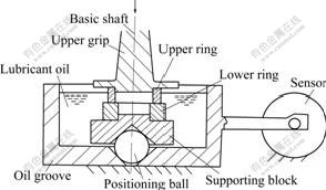
Fig.1 Schematic diagram of MQ-12 improved four-ball wear apparatus
3 Results and analysis 3.1 Effects of composition on stability of amorphous Ni-Fe-P alloys
DSC curve of amorphous Ni78P22 alloy is shown in Fig.2(a). Exothermal reactions were detected at 224, 270, 290, 347 and 429 ℃, respectively. The 224 ℃ peak reaction starts at 190 and 429 ℃ peak reaction starts at 380 ℃. The starting points for other crests cannot be determined because of their wave overlapping.
Although the P content of amorphous Ni69Fe8P23 alloy in Fig.2(b) is close to that of amorphous Ni78P22 alloy, they differ apparently in DSC curve. During continuously heating the amorphous Ni69Fe8P23 alloy 6 exothermal reactions occur respectively at 248, 303, 322, 350, 376 and 442 ℃. The initial temperatures of the exothermal reaction with peaks at 248 ℃ and 442 ℃
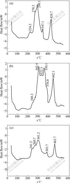
Fig.2 DSC curves of amorphous Fe-Ni-P alloys: (a) Ni78P22; (b) Ni69Fe8P23; (c) Ni72Fe3P25
are 220 ℃ and 395 ℃, respectively. There exist a small shoulder platform at right side of 442 ℃ peak, while the peak at 322 ℃ will disappear during rapid heating. Because of the addition of Fe, the exothermal peaks move towards higher temperatures. The amorphous Ni72Fe3P25 alloy in Fig.2(c) has lower iron content and higher P content than the alloy in Fig.2(b). The DSC curve in Fig.2(c) is similar to that in Fig.2(a), and the exothermal effect of corresponding crests is also similar with each other. 5 exothermal peaks are found at 242, 270, 301, 384 and 463 ℃, respectively. The beginning temperatures of two exothermal reactions with peaks at 242 and 463 ℃ are separately at 210 and 410 ℃.
The crystallizing temperature increases with the Fe content of Fe-Ni-P alloy, which agrees with the results of MASUMOTO et al and HUANG et al[17,18] of amorphous Fe-Ni basis alloys produced by rapid cooling. It can be seen that the thermo-stability of the amorphous Fe-Ni-P alloy is superior to that of the amorphous Ni-P alloy. When used as amorphous alloy, the Fe-Ni-P alloy can stand a higher temperature. The coating with a higher crystallizing temperature can be used at a higher working temperature and has a higher load-carrying ability when used as an antiwear coating after crystallization. This is one of the advantages of the Fe-Ni-P alloy. By comparing Fig.2(a) with Fig.2(c), it can be seen that with increasing P content of the alloy, the first 3 exothermal reaction temperatures have little change, while the fourth and fifth exothermal reactions both move towards higher temperatures. Consequently, the formation of stable crystallized phase and recrystallization are delayed as the P content in the amorphous Fe-Ni-P alloy increases.
3.2 Crystallization activation energy of amorphous Ni69Fe8P23 alloy
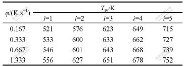
The temperatures of exothermal peaks by the DSC curves of amorphous Ni69Fe8P23 alloy at 10, 20, 40, 80 ℃/min are shown in Table 1.
Table 1 Temperatures of exothermal peaks at various heating rates
From Kissinger’s method we can deduce the following formula:
 (1)
(1)
where φ is the heating rate, Tpi is the peak temperature and E is the activation energy. From the formula we can see  is linear with 1/Tm. The activation energy for each transition can be deduced by the slope of the lines. The relation between
  and
and  can be drawn from data in Table 1. Both of then cater to the Kissinger’s linear relation. So,
 (2)
(2)
1 000/Tpi=X (3)
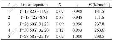
By linear regression method, the variance S, linearly dependent coefficients γ and activation energy E, can be calculated as shown in Table 2. All the linearly dependent coefficients all approach 1, which deduces that the heating rate and the peak temperature cater to Kissinger relation.
Table 2 Activation energy of each exothermal transition
3.3 Effects of heating temperature on stability of amorphous Ni60Fe22P18 alloy
Fig.3 shows the DTA curve of the amorphous Ni60Fe22P18 alloy. It can be seen from Fig.4 that four exothermic reactions have occurred to the amorphous alloy in the heating process. A broad low intensity peak is observed between 250 and 330 ℃ with peak at about 315 ℃. The second exothermic reaction began at 335 ℃ with a weak peak at about 344 ℃, and a narrow, high intensity peek was observed at about 360 ℃. It is difficult to decide the initial temperature because it overlaps the second peek. The peek of the fourth exothermic reaction is at 480 ℃, the initial temperature is about 430 ℃. The scope of transformation tempera- ture is larger.
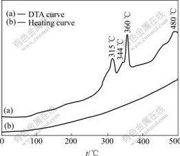
Fig.3 DTA curve of amorphous Ni60Fe22P18 alloy
Fig.4 shows the X-ray diffraction(XRD) patterns for the Ni60Fe22P18 alloys as-deposited and heated at different temperatures. Under as-deposited condition (as shown in Fig.4(a)), only one broad peak was observed at 2θ=44.6?, corresponding to (111) diffraction of Ni or (110) diffraction of Fe. The XRD pattern shows a halo pattern, the characteristic of an amorphous structure. The XRD pattern of the coating heated at 200℃ is still halo.
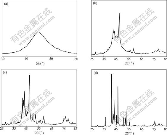
Fig.4 X-ray diffraction patterns of amorphous Ni60Fe22P18 coatings heated at different temperatures: (a) As-cast; (b) 320 ℃; (c) 345 ℃; (d) 600 ℃
When the specimen was heated at 320 ℃ for 1 h, the XRD pattern changed from halo to many sharp peeks, as shown in Fig.4(b). It shows that the coating has crystallized. sin2θ of each diffraction peak is calculated. According to extinction rule of crystal planes, it can be deduced that each of the new phases has a FCC structure whose lattice constant a=5.44 ?, this approaches the lattice constant(a=5.48 ?) of metastable α phase formed by crystallization of the amorphous Ni-P alloy[19]. This may be considered a substitution of metastable α phase in Ni-P alloy in which some Ni atoms is substituted by Fe atoms. It is called α phase as well. The interplanar distance of the other diffraction peaks are agreeable with dHKL of α1 and α2 phase in Ni-P alloy[20]. So we can deduce that 3 new phases α, α1, α2 are formed in the amorphous Ni-Fe-P alloy heated at 320 ℃ for 1 h.
3 new phases Ni(Fe), Ni3P and Fe3P appear in the coating heated at 345 ℃ for 1 h. Ni (Fe) has a FCC structure with lattice constant α=3.614 ?. This is a substitution solid solution formed by dissolving Fe in Ni. Fe can dissolve in Ni liberally and its atomic radius is larger than that of Ni, so dissolving Fe enlarges the lattice constant.
When the Ni60Fe22P18 alloy is heated at 600 ℃ for 1 h the crystallization of the amorphous alloy completed. A Ni3P-type compound with body centered tetragonal (BCT) structure was discovered, with the lattice constants a= 8.971 ? and c=4.401 ?, respectively. They are larger than those of Ni3P, since Fe3P and Ni3P can dissolve each other, and dissolving Fe3P in Ni3P will enlarge the lattice constants. Consequently we deduce that the phase with BCT structure is (Fe, Ni)3P, a solid solution based on the compound Ni3P.
From the above analysis, before the formation of the crystalline metastable phases there exists a process of structure adjustment. The two broad exothermic peak at 315 and 344℃ in Fig.4 might be related to the formation of metastable phases and transformation between the metastable phases. The exothermic reactions at 360 ℃ occurred for the transformation of crystalline metastable phases to stable phases. The stable phases consist of Ni (Fe) and Ni3P-type compounds Ni3P, Fe3P, (Fe,Ni)3P. It is difficult to decide the initial temperature because the third peak overlaps the second peak. So there appear 3 new phases Ni(Fe), Ni3P and Fe3P in the coating heated at 345 ℃ for 1 h. The fourth exothermic reaction at 480℃ is due to the recrystallization of the coating.
3.4 Stability of amorphous Ni-Fe-P alloys during rubbing
Fig.5 shows the variation of the friction factor and wear mass loss of the amorphous Ni-Fe-P coating against GCr15 with sliding time. The friction factor decreases to a stable stage gradually with increasing sliding time. The wear curves of the coating and GCr15 all display run-in and steady wear stages. The wear rates of the coating and GCr15 are 1.75×10⁻⁵ and 1.88×10⁻⁵ g/h, respectively in the steady wear stage, calculated by linear regression method. XRD result shows that the structure of the coating is still at an amorphous state after rubbing 24 h at a pressure of 2.6 MPa.
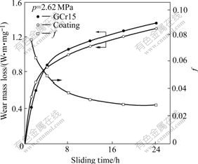
Fig.6 Relationship between friction factor and wear loss of Ni-Fe-P coating with sliding time
The effects of pressure on the friction factor, temperature increments (?t) and wear mass losses are shown in Fig.6. The friction factor and ?t increase with increasing the pressure. The wear mass losses of the coating and GCr15 go through a maximum with the increase of the pressure. They both increase with the pressure and arrive to peaks at 3.78 MPa and then begins to decrease. The structure of the coating is still at an amorphous state after rubbing 4 h under a pressure of 4.94 MPa.
Fig.7 shows the X-ray diffraction pattern of the amorphous Ni-Fe-P alloy coating rubbed against GCr15 for 4 h under a pressure of 6.10 MPa. It has more diffraction peaks than ones of the amorphous Ni-Fe-P coating as-deposited, which shows that the crystallization has taken place on the frictional surface of the amorphous coating under the pressure of 6.10 MPa. It has been determined that the crystallized phase is α-Fe. The surface structure of the coating is of two phases
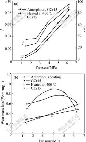
Fig.6 Variation of friction factor, wear loss and ?t with load (t=4 h)
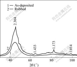
Fig.7 X-ray diffraction patterns of coating rubbed at 6.10 MPa
mixed by amorphous and α-Fe. The results demonstrate that there occur changes of structure and phase in the amorphous coating rubbed under higher-pressure. The critical pressure under which the amorphous Ni-Fe-P coating is stable is about 5.81 MPa.
From the above results it can be seen that the crystallizing phases formed in friction under higher pressure are different from that formed in heat treatment. During rubbing against counterface material, the amorphous coating will suffer not only the pressure, but also the friction force and heat. The atoms on the coating surface will interact with the counterface material. The crystallization process is complex.
In general, the wear losses increase with the load. But the friction under high pressure will result in crystallization of the amorphous Ni-Fe-P coating. It is the crystallization that increases the hardness of the coating, and hence increases the wear resistance. Both the load and crystallization lead to the maximum wear mass losses in Fig.6(b).
4 Conclusions
1) The thermo-stability of the amorphous Ni-Fe-P alloy is superior to that of the amorphous Ni-P alloy. The element content has influence on the stability of amorphous Ni-Fe-P alloy. The crystallization temperature increases with increasing Fe content in the amorphous Ni-Fe-P alloy. The increase of P content in the amorphous Ni-Fe-P alloy delays the appearance of stable crystallization phases and recrystallization.
2) During heating the amorphous Ni69Fe8P23 alloy continuously there exist 6 exothermal reactions which occur respectively at 248, 303, 322, 350, 376 and 442 ℃. Peak at 322 ℃ disappears during rapid heating. The activation energies of other 5 exothermal reactions are 131.5, 111.6, 237.8, 253.6 and 238.5 kJ/mol, respec- tively.
3) The amorphous Ni60Fe22P18 alloy will crystallize when the heating temperature is beyond 250 ℃. Four exothermal peeks are discovered at about 315, 344, 360 and 480 ℃ in the DTA curve. The stable crystallization phases consist of Ni (Fe) and Ni3P-type compounds Ni3P, Fe3P, (Fe,Ni)3P.
4) The pressure and fraction have influence on the stability of amorphous Ni-Fe-P alloy. There occur phase changes on the frictional surface of amorphous Ni-Fe-P coating under higher-pressure. It will crystallize after rubbing under pressure of 6.10 MPa and form a structure of two phases mixed by amorphous+α-Fe. The critical pressure of tribo-stability is about 5.8 MPa.
5) The wear losses of the amorphous Ni-Fe-P/GCr15 pair increase to a maximum and then decrease with increasing the pressure. It is the crystallization rubbed at high pressure that increases the wear resistance of amorphous Ni-Fe-P coating, which leads to the maximum wear mass losses.
References
[1] GAO Cheng-hui, ZHOU Bai-yang. Structure and properties of electrodeposited Ni-Fe-P alloys with various compositions [J]. The Chinese Journal of Nonferrous Metals, 1996, 6(3): 81-85. (in Chinese)
[2] WATANABE T. Amorphous plating [J]. Kinzoku Hyomen Gijutsu, 1987, 38(6): 210-216. (in Japanese)
[3] NANAYAN RAJ, MUNGOLE M N. Hardness control in electrodeposited nickel-phosphorus coating [J]. Metal Finishing, 1985, 83(1): 55-57.
[4] GAO Cheng-hui. Plating of Amorphous Alloys and Their Properties [M]. Beijing: Science Press, 2004. (in Chinese)
[5] DIBARI G A. Some automotive applications of electroless nickle coatings [J]. Metal Finishing, 1983, 81(12): 31-32.
[6] BAUDRAND D W. Trends in electroless nickle plating and look at the future [J]. Plating and Surface Finishing, 1983, 70(12): 24-26.
[7] GAO Cheng-hui, ZHOU Bai-yang. Effects of the composition of electrodeposited Fe-Ni-P alloy on the thermostability and magnetic properties [J]. J Mater Sci Technol, 1997, 13(2): 137-140.
[8] OSAKA T, HOMMA T, SAITO K, TAKEKOSHI A. Co-based soft magnetic films produced by electroless deposition [J]. J Electrochem Soc, 1992, 139(5): 1311-1314.
[9] GAO Cheng-hui. Effects of heat-treatment temperature on the hardness and wear resistance of electrodeposited amorphous Fe-Ni-P alloy coatings [J]. Tribology, 1997, 17(4): 302-307. (in Chinese)
[10] GAO Cheng-hui. Formation mechanism of amorphous Ni-Fe-P alloys by electrodeposition. [J]. Trans Nonferrous Met Soc China, 2005, 15(3): 504-509
[11] GAO Cheng-hui, ZHAO Yuan. Wear Mechanism of Electrodeposited Amorphous Ni-Fe-P Alloys [J]. Trans Nonferrous Met Soc China, 2004, 14(2): 255-259.
[12] CHEN Jin-chang. Thermal stabilization of amorphous FeZr base alloys [J]. Functional Materials of Metal, 1997(1): 22-25. (in Chinese)
[13] LIU Yan-ping, LI Su-qing. The heat theory analysis of amorphous alloys prepared by electroless plating [J]. Chinese Journal of Chemical Physics, 1998, 11(2): 188-192. (in Chinese)
[14] ZHANG Wei-hua, ZHANG Chun-hua, CHEN Bao-guo, YAO Kai-wen, FAN Yi-ning. Study on the thermal stability and catalytic activity of amorphous Co-B alloy ultrafine particles [J]. Journal of Molecular Science, 2003, 19(4): 238-240. (in Chinese)
[15] ZHANG Yi, FANG Yong-kui, DUAN Ji-guo. Structure and crystallization for the amorphous state of Ni-Mo-P coating [J]. Heat Treatment of Metal, 2003, 28(3): 28-32. (in Chinese)
[16] KISSINGER H E. Reaction kinetics in differential thermal analysis [J]. Analytical Chemistry, 1957, 29(11): 1702-1706.
[17] MASUMOTO T, INOUE A, KIMURA H. [J]. J Japan Inst Metals, 1977, 41: 730. (in Japanese)
[18] HUANG Sheng-tao, TAN Cheng-huan. An investigation on the thermal stability and crystallization characteristics of two glassy alloys of Fe-Ni base [J]. J of Wuhan University (Natural Science Edtion), 1981(1): 48-56. (in Chinese)
[19] LAI Zong-he, WU Yu-kun, GUO Ke-xin. Crystallization phases in amorphous Ni-P alloy [J]. Acta Physica Sinica, 1984, 33(8): 1182-1186.
[20] LIANG Jin-zhong, LAI Zong-he, WU Yu-kun, GUO Ke-xin. The hexagonal metastable phase formed in an amorphous Ni-P alloy during crystallization(Ⅲ) [J]. Acta Physica Sinica, 1984, 33(7): 1037-1039.
(Edited by LONG Huai-zhong)
Foundation item: Project(E0410014) supported by the National Science Foundation of Fujian Province, China
Corresponding author: GAO Cheng-hui; Tel: +86-591-22866268; Fax: +86-591-83713053; E-mail: gch@fzu.edu.cn

