
J. Cent. South Univ. (2018) 25: 357-367
DOI: https://doi.org/10.1007/s11771-018-3742-7

Experimental study on acoustic emission characteristics of jointed rock mass by double disc cutter
LIN Qi-bin(�����)1, CAO Ping(��ƽ)1, LI Kai-hui(���)1, 2,CAO Ri-hong(���պ�)1, 3, ZHOU Ke-ping(�ܿ�ƽ)1, DENG Hong-wei(�˺���)1
1. School of Resources and Safety Engineering, Central South University, Changsha 410083, China;
2. Department of Civil and Environmental Engineering, The Hong Kong Polytechnic University,Hong Kong 999077, China;
3. School of Civil, Environmental and Mining Engineering, The University of Western Australia,Perth 6009, Australia
 Central South University Press and Springer-Verlag GmbH Germany, part of Springer Nature 2018
Abstract: The characteristics of joints are crucial factors which influence the penetration efficiency of tunnel boring machine (TBM).Based on the theoretical study, numerical simulation and experimental research, many researchers have studied the interaction between TBM disc cutters and jointed rock mass. However, in most of these works,the effect of joint on rock fragmentation by double disc cutter has been scarcely investigated. Thus, the effects of joint orientation and joint space on rock fragmentation by double disc cutter are highlighted in this study. During the test, jointed concrete specimens are adopted to simulate jointed rock mass. Improved RYL-600 rock shear rheological instrument was employed during the indentation process under disc cutters, and acoustic emission location system was used to analyze the rock damage and physical deterioration. The results show that there are four failure modes and three modes of crack initiation and propagation in jointed rock mass.It is concluded that the existing joint planes have obviously restrained the crack initiation and propagation during the rock fragmentation process. The results also indicate that samples are damaged most seriously when joint orientation equals 60��, which is proved to be the optimum joint orientation in TBM penetration.
Key words: tunnel boring machine (TBM); jointed rock mass; rock fragmentation; crack propagation; acoustic emission
Cite this article as: LIN Qi-bin, CAO Ping, LI Kai-hui, CAO Ri-hong, ZHOU Ke-ping, DENG Hong-wei. Experimental study on acoustic emission characteristics of jointed rock mass by double disc cutter [J]. Journal of Central South University, 2018, 25(2): 357�C367. DOI: https://doi.org/10.1007/s11771-018-3742-7.
1 Introduction
As tunnel boring machine (TBM) technology is extensively used in various rock mass excavation, it is of great significance to predict the performance of rock fragmentation using different methods. During the past decades,many prediction models were obtained by site observations and laboratory tests.HOWARTH [1] studied the effect of joint space on TBM penetration in the laboratory and his experimental results showed that the force for TBM penetration increases with joint space. BRULAND [2] introduced joint orientation into the NTNU TBM performance prediction model. Based on the RFPA model, LIU et al [3] simulated the rock and tools interaction code on rock indentation processes induced by single and double disc cutters. The simulated fragmentation process in the double- cutter indentation test reproduces the side cracks, which initiate under the two indenters, propagate, interact and finally coalesce, chipping the rock between the indenters. Based on the discrete element method (DEM), GONG et al [4, 5] explored the effects of the jointed rock mass on rock breaking by a single disc cutter.It is found that the existing joint planes have affected the crack initiation and propagation during the rock breaking process. BEJARI et al [6] employed DEM to study the influence of joint angle and joint space on rock breaking by TBM cutter and found that for a given joint orientation increasing the joint space causes the TBM penetration to decrease.
Recently, many experiments have been carried out to investigate rock breaking mechanism by disc cutter and a series of research achievements have been obtained [7�C10]. The influence of joint orientation on rock breaking was studied by MA et al [11] and brought out three fragmentation modes. ZOU et al [12] studied the influence of joints on rock indentation by a single TBM cutter,and they found that the spatial characteristics of joints obviously controls the crack mode and has significant limitations to the damage region. TAN et al [13] used the DEM to simulate the jointed rock breaking by TBM cutter and a series of 2-D numerical modeling in jointed rock mass was performed to study the effect of joints on rock breaking by TBM cutter and analyze the load of TBM cutter and the stress distribution of rock.
In past several years, the acoustic emission (AE) technique has been extensively utilized in the analysis of rock mechanics. SHIGEISHI et al [14] analyzed the development of crack identification in concrete materials. CHANG et al [15] used AE to study the fracture and damage mechanisms of rock induced by the accumulation of micro cracks. MORADIAN et al [16] analyzed AE signals generated during shear tests to evaluate on different types of joints (rock�Crock, rock�Cconcrete and concrete�Cconcrete). Based on the force�Cpenetration depth curve and AE parameters, YIN et al [17] and LIU et al [18] studied the indentation process with the different confining stress levels.
In this work, the influence of jointed rock mass on rock fragmentation by double disc cutter is investigated.AE system is applied to monitoring the rock breaking process during the indentation test. Both of the crushed zone and crack initiation and propagation are investigated in the indention test with different joint orientations and spaces. By analyzing the data obtained from indentation test, the crack coalescence and the rock damage process are studied.
2 Experimental
2.1 Specimen preparation
In the test, jointed concrete specimens were adopted to simulate jointed rock mass. The specimens were a mixture of cement, water and sand with a volume ratio of 1: 1: 2. The block dimensions were 200 mm long��140 mm wide��30 mm high. Specimens were cast in special steel mold to ensure surfaces of specimens highly flat. To create filled joints, mica sheets were inserted in the specimens. The orientation between joint plane and tunnel axis varied among 0��, 30��, 60�� and 90��. Four joint spaces were set to 20, 30, 40 and 50 mm respectively, as shown in Figure 1. The basic mechanical parameters of materials are shown in Table 1.
2.2 Penetration tests
RYL-600 rock shear rheometer test machine, which is composed of normal and shear loading system, servo motor control system, measurement and control system and PC system, is shown in Figure 2(a). To conduct the test, RYL-600 rock shear rheological instrument was modified and employed during the indentation process under TBM disc cutters. Acoustic emission location system was used to investigate rock damage and physical deterioration. During the test, a displacement controlled with 0.01 mm/s was applied on the cutter and the confining stress equaled 5 MPa. When the load�Cpenetration curve was in the residual strength stage, loading was stopped. By shooting with the camera in real time, photographs of the damage of specimens were taken and failure modes of the development process were determined. Thus, the acoustic emission testing system was conducted to indicate the micro-fracture failure inside specimens, and analyze the formation mechanism and the characteristics of rock breakage as well.
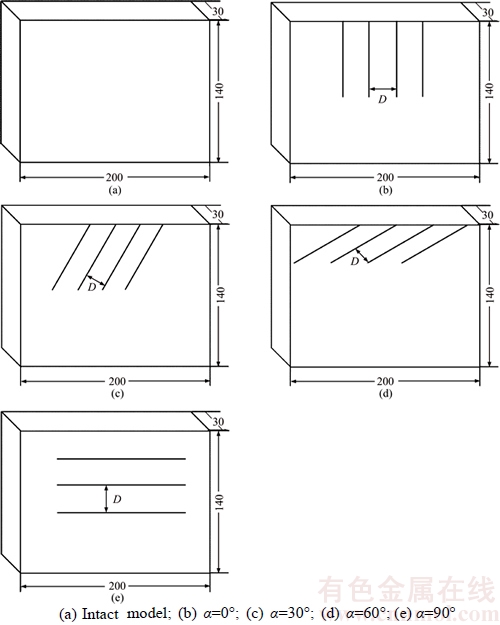
Figure 1 Experimental model:
Table 1 Basic mechanical parameters of materials

3 Rock breaking by double disc cutter in jointed rock mass
3.1 Rock breaking by double disc cutter at different joint orientations and spaces
The rock breaking process under double disc cutter is shown in Figure 3. It can be obtained from this figure that the rock fragmentation process is divided into three stages: crushed zones formation, cracks initiation and propagation and rock chip formation. The orientation between joint plane and tunnel axis varies among 0��, 30��, 60�� and 90��. Four joint spaces are 20, 30, 40 and 50 mm, respectively. Sample failure figures under different joint orientations and spaces are shown in Figure 4. For instance, the joint orientation is 0�� and the joint space (D) is 20 mm in Specimen 0�C20.
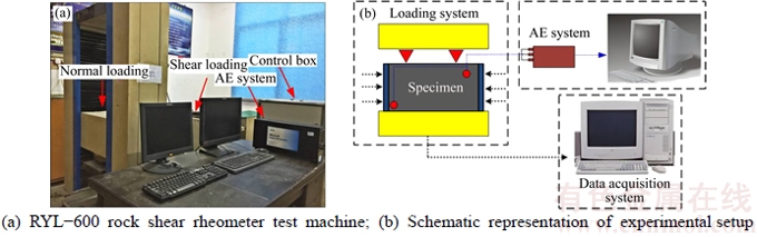
Figure 2 Experimental layout:
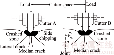
Figure 3 Rock breaking process under double disc cutter
When the joint orientation �� is 0��, because the existing joint plane is parallel to the loading direction, it is difficult to form coalescence between joints. The cracks initiate from the crushed zone and propagate downwards along the joint planes. The failure mode is surface spalling failure, as shown in Figures 4(a), (e), (i) and (m).
When the orientation �� is 30��, each cutter acts on the rock individually and resembles to a single cutter at the beginning. With the increase of the penetration, the Hertzian cracks initiate under the two cutters. The crushed zone is formed right under the two TBM disc cutters. Due to the existing joint planes, the lateral cracks associated with the crushed zones start to propagate and the interaction of lateral cracks induced by the two disc cutters becomes more and more clear. Due to the existing joint surface, the median and lateral cracks propagate under the two TBM cutters, which results in changed crack propagation direction. As the penetration increases, the lateral cracks between the two disc cutters propagate and coalesce with each other and form the rock chip afterwards. The failure mode is shearing failure across the jointed plane, as shown in Figures 4(b), (f), and (g).
When the orientation �� is 60��, the crack initiation and propagation are not the same as those described previously. At the beginning, each cutter acts on the rock individually and resembles to a single cutter. With the increase of the penetration, the crushed zone is formed and cracks initiate from this zone. Due to the effects of existing joint planes, it is found that the lateral cracks propagate along the joint plane and the chip is developed. The failure mode is sliding failure along the jointed plane, as shown in Figures 4(c), (g), (k), (n) and (o).
When the orientation �� is 90��, as the penetration increases, the interaction between rock and disc cutters leads to coalescence of cracks. The median cracks are affected by the existing joint planes and terminate at the joint plane. It is noted that joint planes can hinder cracks from propagating through deeply. At the same time, the chip between the two cutters is formed. The failure mode is splitting failure, as shown in Figures 4(d), (h), (l) and (p).
The final rock fragmentation patterns for specimens with joint spaces of 20, 30, 40 and 50 mm and different joint orientations are illustrated in Figure 4. It is obvious that the existing joint planes have affected the crack initiation and propagation during the rock breaking process. Due to the influence of existing joint planes, there are four failure modes: surface spalling failure, shearing failure across the jointed plane, sliding failure along the jointed plane and splitting failure. There are three possible modes of crack initiation and propagation as well. The first one is that the crack initiates beneath the crushed zone and propagates downwards to the joint plane, as shown in Figures 4(a), (b), (e), (f), (i) and (m); The second one is that the crack initiates from the joint plane and propagates upwards to the free surface, as shown in Figures 4(c), (g), (k) and (o); The third one is that the interaction between rock and disc cutters leads to the coalescence of cracks, as shown in Figures 4(d) and (h).
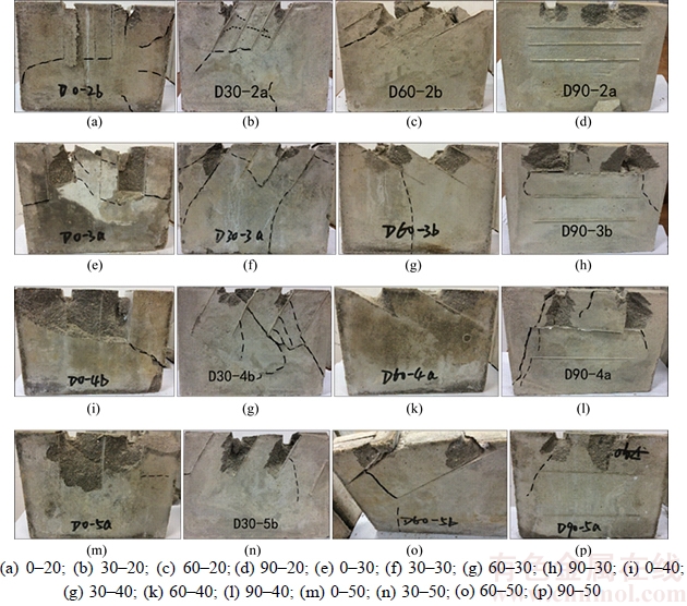
Figure 4 Illustration of sample failure with different joint orientations and spaces:
3.2 Effect of joint orientation and space on TBM penetration efficiency
The cutting efficiency can be evaluated by the specific energy, which is defined as the energy requirement for cutting unit volume of rock fragments [19]. The specific energy is one of the primary parameters of cutter and is used to assess the TBM performance. The effect of joint orientation and space on the TBM penetration efficiency is listed in Table 2.
Rock fragmentation process under the mechanical tools is also the process of energy dissipation [20]. W is the total work done by cutters, which can be obtained by Eq. (1), with the items shown in Figure 5:
 (1)
(1)
where Fi is the indentation load of the ith step; ui is the penetration depth of ith step.
SE is proposed to substitute the specific energy for estimating the penetration efficiency. SE is defined as the ratio of the total work done by cutter to total fragmentation elements, and can be obtained as
 (2)
(2)
where W is the same as that in Eq. (1); V is chipping area.
The relationship of joint orientation and SE is shown in Figure 6. The specific energy firstly decreases with the joint orientation increasing from 0�� to 60��, and then significantly increases with the increasing joint orientation from 60�� to 90��. It can be obtained from Figure 6 that the specific energy achieves the minimum value when the joint orientation ��=60��, which means that the penetration efficiency of two TBM disc cutters reaches the highest value at this moment.
Table 2 Effect of joint orientation and space on TBM penetration efficiency
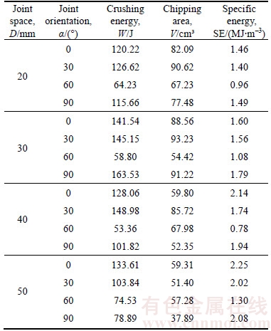
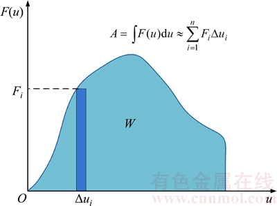
Figure 5 Total work on rock fragmentation by cutter
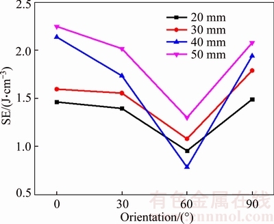
Figure 6 Effect of joint orientation on penetration efficiency
The effect of joint space on TBM rock breaking efficiency is shown in Figure 7. It should be noted that the specific energy increases with the joint space rises, but the penetration efficiency presents the opposite trend. It makes an agreement with the conclusions obtained by BRULAND [2] that, with the decrease of joint space, the TBM penetration efficiency increases obviously.
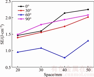
Figure 7 Effect of joint space on penetration efficiency
4 Analysis of rock damage process
The rock fragmentation processes with different joint spaces and orientations are investigated in the indentation tests. According to previous studies [17, 18, 21, 22], through obtaining the force�Cpenetration depth curve and AE activity the process of crack initiation and propagation during the indentation test can be investigated. Based on the obtained curve and AE activity, as an example shown in Figure 8, the rock breaking process under the two TBM disc cutters can be generally divided into four stages described below.
1) Micro cracks closure stage (stage I): At the beginning, each cutter acts on the rock independently and resembles to a single cutter indentation process. When the cutters act on the rock, the pre-existing micro cracks close and the rock is gradually compacted by the indenters. In this stage, AE events remain low and the force- penetration depth curve is an upward concave portion.
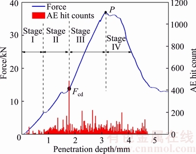
Figure 8 Rock damage stages in indentation test
2) Elastic deformation stage (stage II): In this stage, the force�Cpenetration depth curve is a straight line which is named linear elastic deformation segment. As the loading displacement increases, AE events in unit time gradually increase. Due to the effects of existing joint planes, there are some small fluctuations in the force�Cpenetration curve at the elastic deformation stage.
3) Crack initiation and propagation stage (stage III): This stage includes the stable and unstable crack growth stages. During this stage, cracks in a stable manner propagate and the penetration force increases. With the loading displacement increasing, due to the effect of existing joint planes, the lateral cracks associated with the crushed zones start to propagate, and the interaction of lateral cracks induced by the two disc cutters becomes more and more clear. During the crack unstable growth stage, AE events remain at a relatively high level. This stage is an effective process for rock breaking by TBM. According to YIN��s study [17], the force for crack initiation at the beginning point of the crack unstable growth stage is defined as the critical thrust force (Fcd).
4) Failure stage (stage IV): When the loading continues beyond the peak penetration force (Point P), the penetration force begins to decrease with increasing loading displacement. At this time, the crushed zone is formed under the two TBM disc cutters. Due to the effects of preexisted cracks, there are also a lot of AE hit counts, as shown in Figures 9(c) and (d).
Figure 9 shows the curve of force�Cpenetration depth and AE event parameters at different joint orientations. These figures reveal that the micro cracks closure stage is with few AE events and the force�Cpenetration depth curve is upward concave portion. Due to the effects of existing joint planes, the force�Cpenetration curve has some small fluctuations at elastic deformation stage. When the penetration force reaches Fcd, the AE events in unit time achieve the maximum value. Penetration forces with different joint orientations are listed in Table 3. When the joint orientations vary from 0�� to 30��, Fcd increases from 13.78 kN to 21.42 kN; when the joint orientation achieves 60��, Fcd decreases dramatically to 10.29 kN; with the joint orientation increasing to 90��, Fcd increases to 21.22 kN. As the loading displacement increases, the peak penetration force (Point P) is encountered. It is worth noting that as the joint orientation increases, the peak penetration force decreases until achieving a minimum at the joint orientation ��=60��; when the joint orientation reaches 90��, the peak penetration force increases to 30.37 kN. It has an agreement with the conclusions obtained by LIU et al [18] that the force for TBM penetration reaches the minimum when the joint orientation equals 60��.
The development of magnitude and amplitude of AE events with the loading time for different joint orientations is shown in 3D plots, as shown in Figure 10. The amplitude range of AE events for the different joint orientations is from 50 dB to 100 dB. The percentage of AE events for the different AE amplitude ranges was calculated. When joint orientation ��=0��, the amplitude of AE events is concentrated on 54 dB; when joint orientation ��=30��, the amplitude range of AE events is from 54 dB to 70 dB; when joint orientation ��=60��, the amplitude range of AE events is from 54 dB to 100 dB; when joint orientation ��=90��, the amplitude range of AE events is from 54 dB to 70 dB. The magnitude and amplitude of AE events increase when the joint orientation increases from 0�� to 60�� but the magnitude and amplitude of AE events decrease when the joint orientation increases from 60�� to 90��. It is found that the existing joint planes have obviously restrained the crack initiation and propagation during the rock fragmentation process. The results also indicate that rocks are damaged most seriously when joint orientation equals 60��, which is proved to be the optimum joint orientation for TBM penetration.
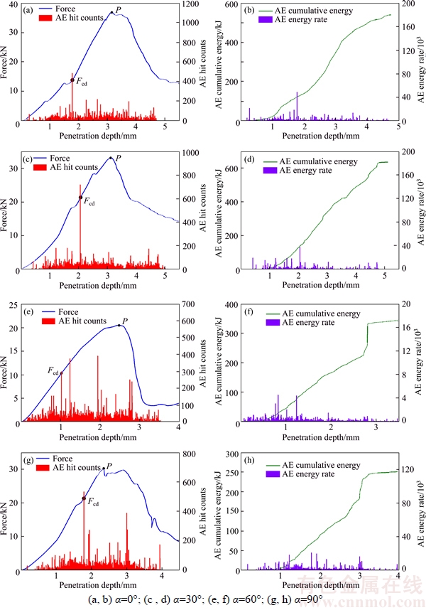
Figure 9 Curve of force�Cpenetration depth (a, c, e, g) and AE event parameters (b, d, f , h) at different joint orientations:
Table 3 Penetration force with different joint orientations
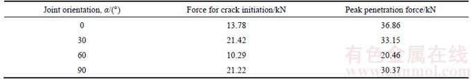
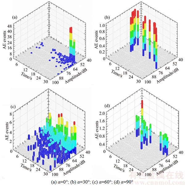
Figure 10 Development of magnitude and amplitude of AE events with loading time for different joint orientations (joint space D=20 mm):
5 Conclusions
1) The failure mode can be classified into four categories: surface spalling failure, shearing failure across the jointed plane, sliding failure along the jointed plane, splitting failure.
2) There are three possible modes of crack initiation and propagation. One is that the crack initiates beneath the crushed zone and propagates downwards to the joint plane. Another is that the crack initiates from the joint plane and propagates upwards to the free surface and the third one is that the interaction between rock and disc cutters leads to coalescence of cracks and chips formation.
3) The rock fragmentation process under the two TBM disc cutters can be generally divided into four stages: micro cracks closure stage, elastic deformation stage, crack initiation and propagation stage and failure stage. In micro cracks closure stage, AE events remain low and the force�C penetration depth curve is an upward concave portion. Due to the effects of existing joint planes, there are some small fluctuations in the force�C penetration curve at the elastic deformation stage. In crack initiation and propagation stage, AE events remain at a relatively high level. Due to the effects of preexisting cracks, there are also a lot of acoustic emission counts in failure stage.
4) It is found that the existing joint planes have obviously restrained the crack initiation and propagation during the rock fragmentation process. The results also indicate that the jointed rock mass is damaged most seriously when the joint orientation equals 60��, which is proved to be the optimum joint orientation for TBM penetration.
References
[1] HOWARTH D F. The effect of jointed and fissured rock on the performance of tunnel boring machines [C]// Proceedings of the International Symposium on Weak Rock. Tokyo, 1981: 1069-1074.
[2] BRULAND A. Hard rock tunnel boring [D]. Trondheim: Norwegian University of Science and Technology, 1998: 1-7.
[3] LIU Hong-yuan, KOU Shao-quan, LINDQVIST P A, TANG Chun-an. Numerical simulation of the rock fragmentation process induced by indenters [J]. International Journal of Rock Mechanics and Mining Sciences, 2002, 39(4): 491-505.
[4] GONG Qiu-ming, ZHAO Jian, JIAO Yu-yong. Numerical modeling of the effects of joint orientation on rock fragmentation by TBM cutters [J]. Tunnelling and Underground Space Technology, 2005, 20(2): 183-191.
[5] GONG Qiu-ming, JIAO Yu-yong, ZHAO Jian. Numerical modelling of the effects of joint spacing on rock fragmentation by TBM cutters [J]. Tunnelling and Underground Space Technology, 2006, 21(1): 46-55.
[6] BEJARI H, REZA K, ATAEI M, JAVAD K. Simultaneous effects of joint spacing and joint orientation on the penetration rate of a single disc cutter [J]. Mining Science and Technology (China), 2011, 21(4): 507-512.
[7] LIU Jing-shuo, CAO Ping, LIU Jie, JIANG Zhe. Influence of confining stress on fracture characteristics and cutting efficiency of TBM cutters conducted on soft and hard rock [J]. Journal of Central South University, 2015, 22(5): 1947�C1955.
[8] LIU Jie, CAO Ping, DU Chun-huang, JIANG Zhe, LIU Jing-shuo. Effects of discontinuities on penetration of TBM cutters [J]. Journal of Central South University, 2015, 22 (9): 3624-3632.
[9] LIU Jie, CAO Ping, HAN Dong-ya. The influence of confining stress on optimum spacing of TBM cutters for cutting granite [J]. International Journal of Rock Mechanics and Mining Sciences, 2016, 88: 165�C174.
[10] ZHANG Xu-hui, XIA Yi-min, ZHANG Yi-chao, TAN Qing, ZHU Zong-ming, LIN Laikuang. Experimental study on wear behaviors of TBM disc cutter ring under drying, water and seawater conditions [J]. Wear, 2017, 12(392, 393): 109�C117.
[11] MA Hong-su, JI Hong-guang. Experimental study of the effect of joint orientation on fragmentation modes and penetration rate under TBM disc cutters [J]. Chinese Journal of Rock Mechanics and Engineering, 2011, 30(1): 155-163. (in Chinese)
[12] ZOU Fei, LI Hai-bo, ZHOU Qing-chun, MO zhen-ze, ZHU Xiao-ming, NIU Lei, YANG Feng-wei. Experimental study of influence of joint space and joint angle on rock fragmentation by TBM disc cutter [J]. Rock and Soil Mechanics, 2012, 33(6): 1640-1646. (in Chinese)
[13] TAN Qing, ZHU Yi, XIA Yi-min, XU Zi-jun, Li Jian-fang, SONG Jun-hua. Influence of joint characteristics on rock fragmentation induced by TBM disc cutter [J]. Journal of Central South University: Science and Technology, 2013, 44(10): 4040-4046. (in Chinese)
[14] SHIGEISHI M, OHTSU M. Acoustic emission moment tensor analysis: development for crack identification in concrete materials [J]. Construction and Building Materials, 2001, 15(5, 6): 311-319.
[15] CHANG S H, LEE C I. Estimation of cracking and damage mechanisms in rock under triaxial compression by moment tensor analysis of acoustic emission [J]. International Journal of Rock Mechanics and Mining Sciences, 2004, 41(7): 1069-1086.
[16] MORADIAN Z A, BALLIVY G, RIVARD P, GRAVEL C, ROUSSEAU B. Evaluating damage during shear tests of rock joints using acoustic emissions [J]. International Journal of Rock Mechanics and Mining Sciences, 2010, 47(4): 590-598.
[17] YIN Li-jun, GONG Qiu-ming, MA Hong-su, ZHAO Jian, ZHAO Xiao-bao. Use of indentation tests to study the influence of confining stress on rock fragmentation by a TBM cutter [J]. International Journal of Rock Mechanics and Mining Sciences, 2014, 72(72): 261-276.
[18] LIU Jie, CAO Ping, HAN Dong-ya. Sequential indentation tests to investigate the influence of confining stress on rock breakage by tunnel boring machine cutter in a biaxial state [J]. Rock Mechanics and Rock Engineering, 2015, 49(4):1�C17.
[19] GONG Qiu-ming, ZHAO Jian, HEFNY A M. Numerical simulation of rock fragmentation process induced by two TBM cutters and cutter spacing optimization [J]. Tunnelling and Underground Space Technology, 2006, 21(12): 1-8.
[20] CAO Ping, LIN Qi-bin, LI Kai-hui, HAN Dong-ya. Effects of joint angle and joint space on rock fragmentation efficiency by two TBM disc cutters [J]. Journal of Central South University: Science and Technology, 2017, 48(5): 1293�C1299. (in Chinese)
[21] LIU Jie, WANG Jun, WAN Wen. Numerical study of crack propagation in an indented rock specimen [J]. Computers and Geotechnics, 2017. DOI: http://dx.doi.org/10.1016/ j.compgeo.2017.10.014.
[22] GENG Qi, WEI Zheng-ying, MENG Hao. An experimental research on the rock cutting process of the gage cutters for rock tunnel boring machine (TBM) [J]. Tunnelling and Underground Space Technology, 2016, 52: 182�C191.
(Edited by YANG Hua)
���ĵ���
˫�й������������������������о�
ժҪ��������Ǻͼ����Ӱ��ȫ�������������(TBM)����Ч�ʵ���Ҫ���ء���ĿǰΪֹ������ѧ���������о�����ֵģ���ʵ�飬�о��˽����Թ������ҵ�Ӱ�졣Ȼ�����ڶ����о��У�������˫�����ι������ҵ�Ӱ��ȴ���١���ˣ������ص��о��˽�����Ǻͼ���˫�����ι�������Ч�ʵ�Ӱ�졣ͨ����װRYL-600��ʯ���������ǣ�����Ԥ�ƽ���ˮ��ɰ���Լ�ģ��������壬�������������ϵͳ����������Ķ�λ�����������о�����������˫�����ι�����������ʯ�ƻ���ȫ���̡�����������������������4���ƻ�ģʽ��3��������չ��ʽ������ʯ�ƻ������У����������Ƶ���չ�����ԵĿ������ã��ڽ������Ϊ60��ʱ�����ƻ������أ���һ����֤�˹������ҵ����Ž���60�㡣
�ؼ��ʣ�������������������壻���ң�������չ��������
Foundation item: Project(11772358) supported by the National Natural Science Foundation of China; Project (2013CB035401) supported by the National Basic Research Program of China; Project (2015zzts262) supported by the Fundamental Research Funds for the Central Universities, China
Received date: 2016-05-20; Accepted date: 2017-12-20
Corresponding author: CAO Ri-hong, PhD Candidate; Tel: +86-15273110027; E-mail: 18229997417@163.com; ORCID: 0000-0002- 6293-6248

