
Process design for multi-stage stretch forming of aluminium alloy aircraft skin
HE De-hua(�ε»�), LI Xiao-qiang(��Сǿ), LI Dong-sheng(���), YANG Wei-jun(��ΰ��)
School of Mechanical Engineering and Automation, Beihang University, Beijing 100191, China
Received 8 September 2009; accepted 24 November 2009
Abstract: A process design approach for multi-stage stretch forming was proposed by combining the strain distribution method and finite element method (FEM) to determine the minimum stage number and deformation amount of each stage. The strain distribution method was used to calculate the deformation amount of each stage and evaluate the formability through a safety criterion. FE simulation was taken as an analysis tool to reveal the deformation behaviour, to predict the strain contour and to determine the process parameters at each stage. To evaluate the effect of heat treatment after pre-strain on occurrence of deformation defects during the subsequent deformation, a multi-stage uniaxial tension test for 2B06 aluminium alloy sheet was carried out. A case study demonstrates that the approach has high reliability and good practicability.
Key words: multi-stage stretch forming; aircraft skin; aluminium alloy; heat treatment
1 Introduction
Aircraft skin is one of the important components composed of the aerodynamic configuration of the aircraft and requires high part accuracy and good surface quality. In the aerospace industry, stretch forming of heat-treatable aluminium sheet is widely used to produce aircraft skin, such as blended wing body sections, fuselage sections and nacelle skins[1]. Due to the significant plastic strain levels in production and the strength requirements in service, it is often impossible that the complex-shaped aircraft skin is manufactured by a single-stage operation[2]. Generally, a multi-stage stretch forming process with intermediate annealing and final quenching is employed to achieve the required part geometry and the final high strength[3].
Compared with the single-stage stretch forming process, the multi-stage operations experience complex deformation and massive heat treatment procedures, which easily leads to sheet metal fracture and deformation defects related to heat treatment. Hence, the process design including stage number and deformation amount of each stage is a key issue, which decides quality and productivity of the final part. Previously, ELISEEV et al [4-6] proposed a method for calculating strain limits of various multi-stage stretch forming processes that referred to intermediate heat treatment. The method can be applied to the initial determination of the stage number and contents of each stage, but the accuracy is not satisfactory because it only uses the analytical approach. Consequently, the process design of multi-stage stretch forming still relied largely on a trial-and-error procedure presently, which is costly and time-consuming[7]. Recently, application of FEM to sheet metal multi-stage forming process has attracted wide attention[8-11]. It plays an important role in revealing the deformation behaviour, predicting the formability of materials and determining the process parameters at each stage. Furthermore, O��DONNELL[12] first implemented a multi-stage stretch forming process of particular interest using FEM. It is noteworthy that the above-mentioned process simulations were carried out under the known stage number, whereas, it is difficult to develop further analysis when the stage number is uncertain. In this study, an approach combining the strain distribution method and FEM is presented to aid the process design for multi-stage stretch forming of aircraft skin, involving the calculation of the stage number and the determination of deformation amount at each stage.
2 Strain distribution method
The intermediate heat treatment procedures are generally performed for recovery of material plasticity in the multi-stage stretch forming of aluminium alloy sheets. Furthermore, the influence of prior strain and different combinations of intermediate heat treatment on the limit strain for necking was presented by GOL��TSEV et al[4] in Eqs.(1)-(2):
 (1)
(1)
where  and
and  are the limited strains for necking in the first stage and nth stage, respectively; ��j is the influence coefficient of the jth intermediate heat treatment; ��i is the strain of the ith stage.
The deformation history in total multi-stage stretch forming can be simplified as a simple loading course. The relationship between strains of different stages can be expressed as
 (2)
(2)
where ��e is the final strain of the formed part while the deformation defects are not considered here.
In order to make the strain distribution of each stage as uniform as possible, the equiprobability condition of deformation defects at any stage proposed by ELISEEV[5] could be defined as Eq.(3) for localization necking:
 (3)
(3)
3 Calculation method
Process design of multi-stage stretch forming is realized as follows.
1) The stage partition is conducted from single- stage to n-stage with intermediate annealing and final quenching. When the i-stage calculation is carried out, deformation amount of each stage can be solved by Eqs.(1)-(3). In particular, in the single-stage operation, the maximum strain can be obtained as the final strain of the desired shape when the deformed sheet is attached on the die completely by FE simulation.
2) To prevent the occurrence of deformation defects such as fracture and surface roughness (so-called orange peel caused by comprehensive actions of deformation at different stages and intermediate heat treatment) at each stage, a safety criterion has to be satisfied simultaneously. According to Eq.(4), it can be estimated whether fracture or orange peel could appear during forming:
 ��
�� �� (4)
where  is the critical strain of the ith stage leading to the impermissible surface roughness in the (i+1)th stage; So is the safety margin coefficient of presence of orange peel, and as a rule, So=0.1-0.3; S represents the safety margin coefficient of fracture, and it is defined in a similar way as follows[13]:
 (5)
(5)
where  is the major principal strain of the forming limit diagram (FLD); src="/web/fileinfo/upload/magazine/126/4398/image026.gif" width=43> is the margin area of the FLD by changing the distance from the margin curve to the failure curve.
3) The mechanism motion loading can be calculated based on FE simulations when the strain of each stage is confirmed. In FE simulations, results of the previous stage are used for analysis of the subsequent stage. Simultaneously, stress and strain of sheet elements are set as zero to consider the effect of heat treatment. In particular, material constitutive model of annealed state is used for intermediate stages, while material constitutive model of as-quenched state is applied for the final stage.
4 Multi-stage uniaxial tension test
Previous work on multi-stage tests, only considering deformation fracture, has been studied by uniaxial tensile test[2], pre-straining in an out-of-plane biaxial fashion [14] and a more comprehensive test programme[15]. Contributing to the fact that the strain path of material deformation of longitudinal stretch forming for aircraft skin is particularly close to uniaxial tension state[16], a two-stage uniaxial tension test with quenching was considered to evaluate the effect of pre-strain on the limit strain for necking and the critical strain without formation of orange peel, respectively.
4.1 Uniaxial tension specimens
The sheet used throughout this study was 2B06 aluminium alloy, 0.8 mm in thickness, supplied in a fully annealed condition. Flakes (250 mm��120 mm) were cut from the parent material, where the 250 mm dimension was aligned with the rolling direction of the material and the uniaxial loading axis.
4.2 Test scheme
Firstly, flakes were pre-strained to different nominal strain levels ranging 1.6%, 3.2%, 4.8%, 6.4%, 8%, 9.6%, 11.2% and 12.8%, respectively. Secondly, the tensioned flakes were quenched, then rapidly stored at a temperature of not higher than -20�� to prevent natural aging at ambient temperature. Thirdly, four repeat specimens were removed from the pre-strained flakes in accordance with GB/T 228��2002 (parallel width of 12.5 mm over a gauge length of 200 mm). Thirty-two tensile test specimens in total were given, which were used in two experiments mentioned above under the same condition. Finally, individual specimens were subjected to tension again until to fracture within 30 min of removal from cold storage.
4.3 Test results
Results of the first experiment are plotted in Fig.1. It can be seen from Fig.1 that the limited strain for necking at the second stage decreases with increasing pre-strain. The data points are scattered to some degree because the heat treatment procedure prior to test is difficult to achieve consistency accurately. Even so, a linear relation can be obtained by the least squares method, which conforms to the linear relation in Eq.(1) under the two-stage condition. The influence coefficient of intermediate heat treatment can be obtained as ��1=0.433.
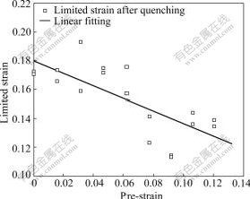
Fig.1 Effect of pre-strain on limited strain for necking
Then surface roughness test, the second experiment, was carried out to quantify the effect of the pre-strain on surface roughness during the tension of the second stage. This experiment was repeated, called A and B group, respectively. The roughness, described by profile arithmetic average error Ra and ten-point height of irregularities Rz, was detected by TR100 surface roughometer. Fig.2 exhibits the effect of pre-strain on surface roughness. It is found that the critical strain of the presence of orange peel is 0.077. When the strain exceeds 0.077 in the first stage, specimen surfaces become significantly rough in the second stage, as shown in Fig.3. The value of Ra increases from 1 ��m to 2-3 ��m, while the value of Rz increases from 8-10 ��m to 10-14 ��m.
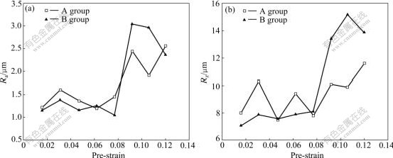
Fig.2 Effects of pre-strain on surface roughness Ra (a) and Rz (b)
src="/web/fileinfo/upload/magazine/126/4398/image031.jpg" width=490>
Fig.3 Orange peel phenomenon (A group)
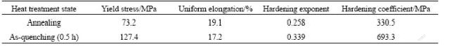
In addition, the mechanical property of annealing and quenching state along the rolling direction could be obtained from uniaxial tension tests, respectively, as listed in Table 1.
Table 1 Mechanical property of material
5 Case study
5.1 Problem description
A skin part of blended wing body configuration was discussed here. It has a complicated shape with convex along longitudinal direction and combination of convex and concave along transverse direction, as exhibited in Fig.4(a). The incoming material as supplied was the same as that of uniaxial tension test. The initial blank was designed to be rectangular of 5 000 mm��980 mm. The length direction was parallel to the material rolling direction and subjected to stretch in the subsequent forming operation.
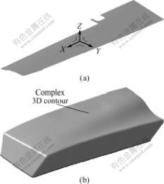
Fig.4 Tool geometry: (a) Part; (b) Die
5.2 Results and discussion
The influence coefficient of intermediate heat treatment ��1=0.433 and the critical strain of presence of orange peel  0.077 were confirmed by the previous test. The limited strain for necking src="/web/fileinfo/upload/magazine/126/4398/image039.gif" width=29>0.175 was available from Table 1. Moreover, safety margin coefficient S=0.45 could be determined by FLD tests. As a rule, So=0.1.
The calculation procedure was carried out as follows.
Firstly, the annealed sheet was quenched and formed in the as-quenched state, assuming that this part can be produced by the single-stage operation. The single-stage operation was analyzed based on the established FE model, as exhibited in Fig.5. Fig.6 represents the strain contour in the single-stage operation. It is illustrated that the maximum strain, ��e=0.127, occurs in the elliptic region. As designated in Eq.(2), this maximum strain is regarded as the final strain of the formed part. Then, formability evaluation of the single-stage operation was performed according to Eq.(4). Unfortunately, the safety criteria could not be satisfied so that the two-stage operations have to be implemented.
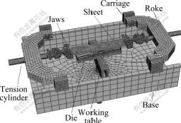
Fig.5 FE model
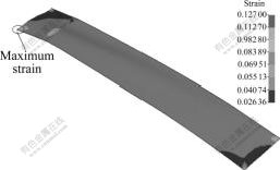
Fig.6 Strain contour in singe-stage stretch forming
Secondly, the two-stage stretch forming was followed. Correspondingly, the sheet was annealed and quenched in the first and second stage. By substituting ��e, and ��1 into Eqs.(1)-(3), ��1, ��2 and could be computed as 0.069, 0.058 and 0.146, respectively. In the same way, formability evaluation was conducted again. Luckily, the safety criteria were satisfied well. This meant that this part could be manufactured by the two-stage stretch forming. To further check its formability, FE simulation was developed. The mechanism motion loading was determined by the strain of each stage, which was used as boundary conditions of FE simulations as well as loadings in practice. Fig.7 shows the strain contour in the two-stage stretch forming. It can be seen from Fig.7 that the maximum strains are approximately 0.069 4 and 0.057 9, respectively. They correspond well with the calculated results before by the strain distribution method.

Fig.7 Strain contour in two-stage stretch forming: (a) Stage 1; (b) Stage 2
As discussed above, this part was produced in practice, as shown in Fig.8. It is found that there are no deformation defects such as fracture or presence of orange peel. Furthermore, the shape discrepancy from the sheet to the die in the normal direction is below 0.5 mm, which satisfies the test standard of aircraft skin. This indicates that the stage number and strain distribution at each stage are reasonable. The process design method of multi-stage stretch forming is feasible, which can be applied to multi-stage stretch forming for complex-shaped aircraft skin.
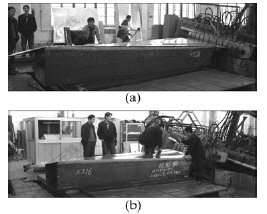
Fig.8 Parts formed in two-stage stretch forming: (a) Stage 1; (b) Stage 2
6 Conclusions
1) Based on the strain distribution method and FEM, a process design approach of multi-stage stretch forming is presented for aircraft skin to determine the minimum stage number and deformation amount of each stage.
2) By the multi-stage uniaxial tension test, the influence of prior strain on the succeeding deformation is revealed. The influence coefficient of intermediate heat treatment can be obtained as ��1=0.433 and the critical strain of the presence of orange peel is 0.077.
3) Through an example analysis, it is demonstrated that this approach is capable of performing process design for multi-stage stretch forming of complex shapes to prevent the occurrence of deformation defects.
4) Future work may include more complicated aircraft skin that concerns more comprehensive strain paths, more stages and intermediate heat treatments.
References
[1] WISSELINK H H, van den BOOGAARD A H. Finite element simulation of the stretch forming of aircraft skins [C]// Proceedings of the 6th International Conference and Workshop on Numerical Simulation of 3D Sheet Metal Forming Processes. Detroit: American Institute of Physics, 2005: 60-65.
[2] STRAATSMA E N, VELTEROP L. Influence of heat treatments and straining steps on mechanical properties in the stretch forming process [C]// Proceedings of the 9th International Conference on Aluminum Alloys. Australia: Institute of Materials Engineering Australia Ltd., 2004: 771-776.
[3] O��DONNELL M, LEACOCK A G, BANABIC D, BROWN D, MCMURRAY R J. The effect of pre-strain and solution heat treatment on the formability of a 2024 aluminium alloy [J]. International Journal of Material Forming, 2008, 1(Supplement 1): 257-260.
[4] GOL��TSEV A M, DEL G D, ELISEEV V V. Analysis of the strain capacity of aluminum alloy D16AMO [J]. Russian Metallurgy (Metally), 1989, 3: 75-78.
[5] ELISEEV V V. Calculation of transitions in stretch forming [J]. Soviet Aeronautics, 1991, 34(2): 108-111.
[6] GOL��TSEV A M, DEL G D, ELISEEV V V. Prediction of scrapping criteria of sheet material in multipass deformation [J]. Metal Science and Heat Treatment, 1989, 31(5/6): 473-476.
[7] CHEN W, LIU Z J, HOU B, DU R X. Study on multi-stage sheet metal forming for automobile structure-pieces [J]. Journal of Materials Processing Technology, 2007, 187/188: 113-117.
[8] SKJOEDT M, BAY N, ENDELT B, INGARAO G. Multi stage strategies for single point incremental forming of a cup [J]. International Journal of Material Forming, 2008, 1(Supplement 1): 1199-1202.
[9] JIANG Shu-yong, ZHENG Yu-feng, REN Zheng-yi, LI Chun-feng. Multi-pass spinning of thin-walled tubular part with longitudinal inner ribs [J]. Transactions of Nonferrous Metals Society of China, 2009, 19(1): 215-221.
[10] LANG L, GU G, LI T, ZHOU X. Numerical and experimental confirmation of the calibration stage��s effect in multi-operation sheet hydroforming using poor-formability materials [J]. Journal of Materials Processing Technology, 2008, 201(1/3): 97-100.
[11] HEUNG K, SEOK H. FEM-based optimum design of multi-stage deep drawing process of molybdenum sheet [J]. Journal of Materials Processing Technology, 2007, 184(1/3): 354-362.
[12] O��DONNELL M. Finite element modelling of a multi-stage stretch-forming operation using aerospace alloys [D]. Belfast: University of Ulster, 2003.
[13] Engineering Technology Associates, Inc. eta/Post. User��s Manual[M]. Shanghai: Engineering Technology Associates, Inc., 2007. (in Chinese)
[14] DRYSDALE R J, BAHRANI A S. The effect of annealing processes on the limit strains of an aluminium alloy [J]. Journal of Mechanical Working Technology, 1985, 11: 105-114.
[15] O��DONNELL M, BANABIC D, LEACOCK A G, BROWN D, MCMURRAY R J. The effect of pre-strain and inter-stage annealing on the formability of a 2024 aluminium alloy [J]. International Journal of Material Forming, 2008, 1(Supplement 1): 253-256.
[16] JIN Hai-xia. Basic experiment research and numerical simulation on mirror aluminum alloy skin stretch forming [D]. Beijing: Beijing University of Aeronautics and Astronautics, 2006: 12-23. (in Chinese)
Corresponding author: LI Xiao-qiang; Tel: +86-10-82316584; E-mail: littlestrong@me.buaa.edu.cn
DOI: 10.1016/S1003-6326(09)60257-0
Foundation item: Project(2006AA04Z143) supported by the National High-tech Research and Development Program of China; Project(2006BAF04B00) supported by the National Key Technologies R&D Program of China; Project(2007ZE51055) supported by the Aviation Science Foundation of China
(Edited by LI Xiang-qun)

