ѭ����ʽģ���Ʊ�Mg-Si�Ͻ����֯����ѧ����
��Դ�ڿ����й���ɫ����ѧ��(Ӣ�İ�)2014���1��
�������ߣ�J. METAYER Ҷ �� �� � ������ �� �� F. MOLLET
����ҳ�룺66 - 75
�ؼ��ʣ�þ�Ͻ�Mg2Si��ѭ����ʽģ�ͣ�ĥ����֯
Key words��magnesium alloy; Mg2Si; cyclic closed-die forging; wear; microstructure
ժ Ҫ�������Ʊ�Mg-xSi (x=0, 1.5��3.3)�Ͻ��ٲ���һ���µĴ����Ա��η�������ѭ����ʽģ��(CCDF)��450 ��C����1��3��5���μӹ���ͨ��ѭ����ʽģ�ͣ��ִ��Mg2Si�����������С�鲢�ҷֲ����Ӿ��ȣ����ϵ�����ǿ�ȡ��쳤�ʺ�Ӳ�ȵõ�����ߡ���5���μӹ���Mg-1.5%Si�Ͻ��ǿ�Ⱥ��쳤��ͬʱ�õ���ߣ�����ǿ�ȴ�142 MPa���쳤��Ϊ8%�����øɻ���Ħ����һ�������������ܡ��������������Si�����ͼӹ����ε����ӣ����ϵ���ĥ���ܵõ�����ߣ��ӹ�1���κ�������ߣ��ټ������ӵ���ʱ��߲����ԡ���5���μӹ���Mg-3.3%Si�Ͻ����ĥ�Աȴ�þ�ĸ�38%������Archard���̺�Ħ��Ч������ĥ�Ե���߹������֯��ϸ���;��Ȼ���
Abstract: Mg-xSi (x=0, 1.5, 3.3) alloys were fabricated and subjected to cyclic closed-die forging (CCDF), a new severe plastic deformation process, at 450 ��C for 1, 3, and 5 passes. With applying CCDF, tensile strength, elongation and hardness increase, while coarse Mg2Si particles break into smaller pieces and exhibit more uniform distribution. Mg-1.5%Si alloy exhibits a combination of improved strength and elongation after 5 passes of CCDF processing. The tensile strength is about 142 MPa and elongation is about 8%. The improvement in mechanical properties was further characterized by dry sliding wear testing. The results show that wear resistance improves with silicon content and CCDF process passes, particularly the first pass. The wear resistance increases by about 38% for Mg-3.3%Si after 5 passes of CCDF compared with pure Mg. The improvement of wear is related to microstructure refinement and homogenization based on the Archard equation and friction effect.
Trans. Nonferrous Met. Soc. China 24(2014) 66-75
J. METAYER1,2, Bing YE1,3, Wei GUO1,3, Qu-dong WANG1,3, Hao ZHOU1,3, F. MOLLET1,2
1. National Engineering Research Center of Light Alloy Net Forming, Shanghai Jiao Tong University, Shanghai 200240, China;
2. Arts et  ParisTech engineering school, Angers, France;
3. State Key Laboratory of Metal Matrix Composites, Shanghai Jiao Tong University, Shanghai 200240, China
Received 1 November 2012; accepted 15 March 2013
Abstract: Mg-xSi (x=0, 1.5, 3.3) alloys were fabricated and subjected to cyclic closed-die forging (CCDF), a new severe plastic deformation process, at 450 ��C for 1, 3, and 5 passes. With applying CCDF, tensile strength, elongation and hardness increase, while coarse Mg2Si particles break into smaller pieces and exhibit more uniform distribution. Mg-1.5%Si alloy exhibits a combination of improved strength and elongation after 5 passes of CCDF processing. The tensile strength is about 142 MPa and elongation is about 8%. The improvement in mechanical properties was further characterized by dry sliding wear testing. The results show that wear resistance improves with silicon content and CCDF process passes, particularly the first pass. The wear resistance increases by about 38% for Mg-3.3%Si after 5 passes of CCDF compared with pure Mg. The improvement of wear is related to microstructure refinement and homogenization based on the Archard equation and friction effect.
Key words: magnesium alloy; Mg2Si; cyclic closed-die forging; wear; microstructure
1 Introduction
Magnesium and its alloys are amongst the lightest engineering alloys known, and there is a great interest for automotive and aerospace industries [1,2], where mass saving is critical. However, Mg and its alloys without rare earth element exhibit a rather low strength compared with steels and most of aluminum alloys, the widely used structural materials. In fact, the hexagonal crystal structure of Mg affects the fundamental properties of Mg alloys such as hardness, elastic modulus and tensile strength. Moreover, the wear easily occurs by friction with a counter material [3-5].
Recent studies have shown that the addition of hard particles and lubricants improves tribological performance of the conventional magnesium alloys such as hardness, yield strength, and wear resistance [6-9]. It is noted that the Mg2Si particles exhibit a high melting point (1085 ��C), a high elastic modulus (120 GPa), a low thermal expansion coefficient (7.5��10-6 K-1), and a compatible interface with Mg [10-12]. Also, silicon has a low maximum solid solubility around 0.003% (mole fraction) in Mg, which promotes the precipitation formation from liuquid during casting [6]. Therefore, there is a strong interest in developing high performance Mg-Si series alloys to exploit the strength of Mg2Si particles for much improved mechanical properties including strength, hardness, creep resistance [13], and wear resistance. To have a clear understanding of the strength of Mg2Si particles, it is interesting to study a simple system, the addition of silicon in pure magnesium.
However, as-cast Mg-Si alloys have a low strength and ductility due to large particle sizes of Mg2Si [14]. A significant way to improve the mechanical properties of Mg-Si alloy is to reduce the size of the particles and then refine their microstructure [15]. This can be achieved using severe plastic deformation processes (SPD), such as equal-channel angular pressing (ECAP) [16,17], accumulative rolling bonding (ARB) [18], high pressure torsion (HPT) [19], cyclic-extrusion- compression (CEC) [20], repetitive upsetting (RU) [13,21], accumulative back extrusion (ABE) and cyclic closed-die forging (CCDF) [22]. The principle of SPD is to impose high strains in the billet to rearrange the dislocations resulting in fine grains below sub micrometres or even nanometres scale. Inflicting SPD process refines Mg2Si phases due to flow constraint between matrix and the particles [23]. In comparison with other SPD processes, CCDF produces more intensive strains per pass, and more uniform structure of the material may be achieved through multi-directional deformation. However, very limited investigations have been carried out on CCDF of breaking Mg2Si particles in Mg-based materials. GUO et al [24,25] investigated the microstructure and tensile mechanical properties of AZ31-1.7%Si composite after CCDF processing at 350 ��C. They found that the coarse Mg2Si particles broke into smaller pieces, and the yield strength and elongation were notably increased after 5 passes. Accordingly, the aim of the present work is to investigate the microstructure and mechanical properties including wear resistance of Mg-Si alloy processed by CCDF. Effects of silicon addition on the microstructure and mechanical properties of the alloy are studied.
2 Experimental
2.1 Materials
Pure Mg was used as starting materials to prepare the designed Mg-2Si and Mg-5Si (mass fraction, %) alloys. The whole smelting was carried out in an electric resistance furnace protected by the gas mixture of 0.5% SF6 and 99.5% CO2 (volume fraction). After Mg ingot was melted up to 780 ��C in a steel crucible, silicon particles with an average diameter of 1 mm were added to the melt. The melt was manually stirred for about 5 min using a steel rod and held for 20 min to make sure that the silicon was completely dissolved. When the temperature was cooled below 710 ��C, the dross was skimmed and the melt was poured into a steel mold preheated to 200 ��C to get a 100 mm �� 100 mm �� 160 mm rectangular ingot. The actual silicon content was measured with an inductively coupled plasma optical emission spectrometer (ICP-OES), and the nominal Mg-2Si and Mg-5Si composites were actually Mg-1.5%Si and Mg-3.3%Si, respectively.
2.2 CCDF processing
Before CCDF, as-cast Mg-Si ingot was machined into rectangular samples with a square of 100 mm and a height of 20 mm. The schematic representation of the CCDF process is shown in Fig. 1. The die consists of a lower die with a chamber of 100 mm��100 mm cross-section and a punch of the same section for external loading which moves vertically inside the chamber. A well-lubricated sample with graphite lubricant was placed into the lower die and then heated to 450 ��C and maintained at this temperature for 30 min. The sample was pressed into the lower die by the punch at a constant speed of 3 mm/s. After pressing, each sample was taken out and rotated 90�� around Z-axis in the same direction, and reinserted into the lower die for next pressing. In this way, each sample was rotated 90�� around Z-axis between consecutive passes. In this manner the samples were subjected to 1, 3, and 5 passes, respectively. After the CCDF processing, the sample was cooled to room temperature in air.
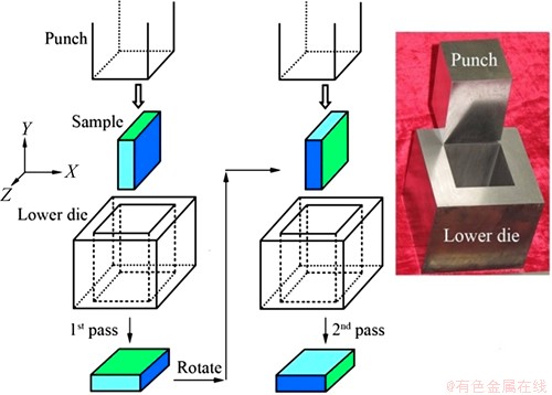
Fig. 1 Schematic representation of CCDF process
Microstructure of the samples were examined by optical microscopy (OM) after mechanical polishing and etching for 30 s using a solution of 1 g oxaldehyde, 1 mL nitric acid, 1 mL acetic acid in 150 mL water. Microstructure at four typical positions inside the sample was examined. The crystal phases in the Mg-Si samples were investigated and identified using X-ray diffraction (XRD) with Cu K�� radiation at a scan speed of 2 (��)/min in a Shimadzu LabX XRD-6000 diffractometer. The hardness tests were performed using a Vickers indenter under a test load of 49 N and a dwell time of 30 s.
2.3 Tensile tests
Flat dog-bone tensile specimens (10 mm in gage length, 3.5 mm in gage width, and 2 mm in gage thickness) were created by electrical discharge machining. The specimen was machined from the center portion of X-Z plane with the gage length direction parallel to the Z-axis. Tensile tests were performed at room temperature with an initial strain rate of 8.3 �� 10-4 s-1.
2.4 Wear tests
Dry sliding wear tests were conducted using a ball-on-plate configuration. The counter-faces were AISI 52100 steel bearing balls of 6 mm in diameter with hardness of 61 on the Rockwell-C scale. Before the test, rectangular specimens with dimensions of 50 mm �� 30 mm �� 5 mm were cut from the ingot by electrical discharge machining. The wear tests were conducted at room temperature in a sliding distance range of 1000-2000 m, and a velocity range of 0.06-0.12 m/s for a constant load of 10 N. The stroke length was 30 mm on the center surface of the plate specimen. Finally, scanning electron microscopy (SEM) was employed to observe the fracture surface.
3 Results and discussion
3.1 Microstructure
The XRD pattern taken from as-cast Mg-3.3%Si alloy is shown in Fig. 2. It indicates that the alloy is composed of ��-Mg (matrix) and Mg2Si phases. Based on the Mg and Mg2Si phase information and chemical composition, Mg-3.3%Si alloy has a volume fraction of 92% Mg and 8% Mg2Si. The initial microstructures of Mg-1.5%Si and Mg-3.3%Si alloys are shown in Fig. 3. In the as-cast Mg-1.5%Si alloy, the main features are the Chinese script shaped Mg2Si particles and bars of eutectic microstructure, whereas the Mg-3.3%Si alloy exhibits arranged bars of eutectic phase and polygonal shaped coarse Mg2Si particles with an average particle size of 33 ��m. The Mg2Si particles in the as-cast Mg-1.5%Si alloy are much finer than those in the as-cast Mg-3.3%Si alloy. The microstructural evolution of Mg-3.3%Si alloy subjected to 1, 3 and 5 CCDF passes at 450 ��C is shown in Fig. 4. Samples were taken from both radial direction Z and direction Y parallel to the forging direction. After 1 pass of CCDF processing, the samples exhibit an inhomogeneous structure. The particle distribution consists of coarse particles surrounded by much finer particles, although the coarse particles occupy a significantly larger area fraction. Some coarse particles break into smaller ones without changing the area fraction. However, this structure is transitional. With further CCDF processing coarse particles continue breaking up, and the microstructure becomes more homogenous and refined. After 3 passes, the particle distribution tends to be more uniform but is still not homogenous with mixed coarse and fine particle structure. The particles continue breaking into smaller pieces and start to spread in the alloy but not very far (around 700 ��m). The particles in the Z direction are still slightly smaller than those in the Y direction. Further forging to 5 passes, a reasonably refined and homogeneous microstructure is obtained in both Y and Z directions.
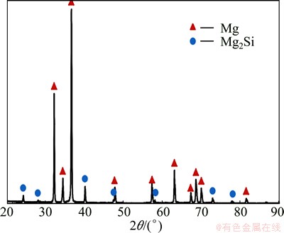
Fig. 2 XRD pattern of as-cast Mg-3.3%Si alloy
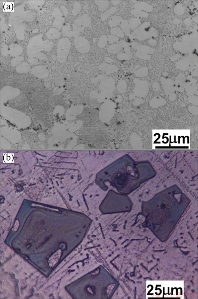
Fig. 3 Microstructures of as-cast Mg-1.5%Si (a), and Mg-3.3%Si (b) alloys before CCDF processing
In order to further characterize microstructure refinement quantitatively, the particle sizes of Mg2Si phase in Mg-3.3%Si before and after 1, 3 and 5 CCDF passes are plotted in Fig. 5. With increasing the number of passes the average size of Mg2Si particles decreases constantly. However, for each number of passes, the particles in the Z direction are lightly smaller than in the Y direction (the forging direction). During the CCDF process, the alloy is compressed in a specific direction parallel to the Y direction. The particles in the X and Z directions are then more deformed and smaller than those in the Y direction. After 1 pass of CCDF processing, the average particle size of Mg2Si phase is drastically refined to 26.8 ��m in Y direction and 19.9 ��m in Z direction, i.e. a maximum 40% refinement. Further forging to 3 passes, the particle size is still refined, especially in Z direction. After 5 passes, the average size of Mg2Si particles is 14.8 ��m in Y direction and 12.5 ��m in Z direction, which are 55% and 62% of total particle size reduction respectively. The CCDF significantly refines the microstructure and increases the uniformity of the particle distribution [21].
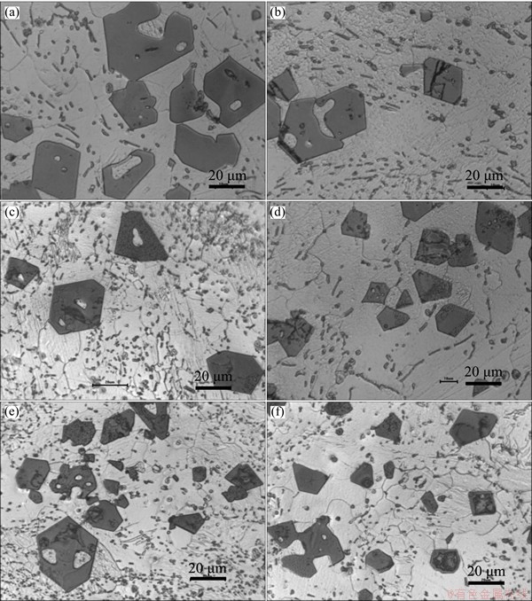
Fig. 4 Microstructures of Mg-3.3%Si alloy after CCDF processing at 450 ��C viewed from Y direction (left column) and Z direction (right column) for 1 pass (a, b), 3 passes (c, d), and 5 passes (e, f)
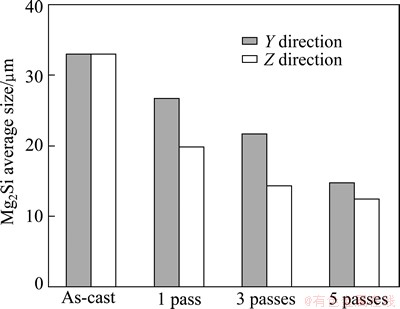
Fig. 5 Average size of Mg2Si particles with pass number in Mg-3.3%Si alloy
The microstructural evolution of Mg-1.5%Si alloy subjected to 3 and 5 CCDF passes at 450 ��C is shown in Fig. 6. One striking feature is that Mg2Si particle size does not vary much with different CCDF passes compared with Fig. 3. The microstructure is relatively homogeneous and the effect of CCDF in Mg2Si particle refinement is minimal. However, the distribution of Mg2Si particle becomes more uniform with CCDF passes. It is expected that the interface bonding between Mg and Mg2Si particles is also enhanced through CCDF. After 5 passes of CCDF, the fine Mg2Si particle distribution is relatively uniform. The Mg grain size tends to decrease with CCDF although it is not significant.
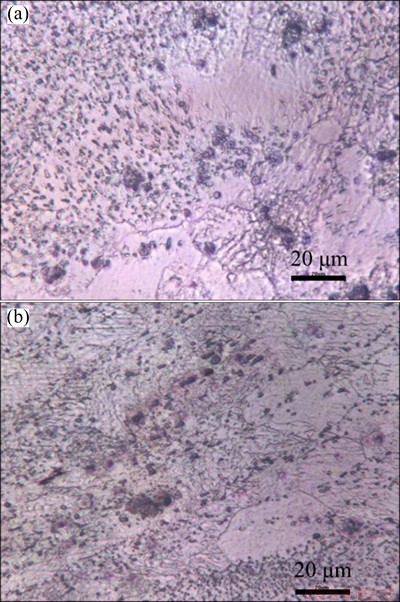
Fig. 6 Microstructures of Mg-1.5%Si alloy after 3 passes (a) and 5 passes (b) of CCDF processing at 450 ��C viewed from Z direction
The influence of CCDF processing on the Mg2Si morphology is also significant. After 1 pass, the regular distribution of dendritic and Chinese script type Mg2Si particles is changed. Some coarse Mg2Si particles are broken up into smaller pieces, leading to an inhomogeneous structure. With further increasing passes, the coarse Mg2Si particles continue to break under the strain imposed by the CCDF process. After 5 passes, the Mg2Si particles have random shapes after being broken by the CCDF, and the eutectic bars of magnesium silicide are randomly sprinkled and broken as well. In the as-cast alloy the orientation of the Mg2Si particles is random, as confirmed with XRD intensity data, which matches with the standard Mg2Si intensity profile. The random texture is beneficial for the mechanical properties of the Mg-Si alloys and has a great influence on the resistance of magnesium alloys [26].
3.2 Hardness
The mean hardness in X, Y and Z direction for pure Mg, Mg-1.5%Si and Mg-3.3%Si alloys for 1, 3, and 5 CCDF passes is shown on Fig. 7. The results reveal that the addition of silicon to pure Mg significantly increases the hardness, especially after 1 pass, compared with pure Mg. The hardness increases from HV31 to HV43.3 from Mg2Si hard particle strengthening. The hardness of Mg-3.3%Si alloy is higher than that of Mg-1.5%Si with increasing Mg2Si volume fraction. Moreover, the hardness of Mg-Si alloys increases slightly with the increasing number of passes, particularly for pure Mg. It is possible that recrystallization and grain growth actively operate at 450 ��C and make the grain refinement of CCDF process less effective. The results show that SPD enhances the hardness from both grain refining and particle dispersing. Thus, the addition of silicon combined with grain refinement processed by CCDF improves the hardness of Mg-Si alloys.
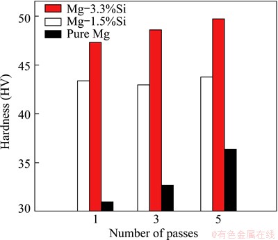
Fig. 7 Effect of pass number on hardness with different Mg-Si compositions
3.3 Tensile properties
Room temperature tensile stress��strain curves of pure Mg, as-cast Mg-1.5%Si and Mg-3.3%Si alloys are shown in Fig. 8(a). Variation of ultimate tensile strength (UTS) and elongation with pass number is correspondingly plotted in Fig. 8(b). The pure Mg alloy exhibits a significantly high elongation compared with the Mg-Si alloys. The addition of silicon creates coarse Mg2Si particles that are more brittle and prone to crack from initial defects shown in Fig. 4. The magnesium alloy becomes less ductile with addition of silicon and its elongation decreases drastically: 87% decrease from pure Mg to Mg-3.3%Si alloy. On the other hand, with particle strengthening of Mg2Si, the addition of silicon increases tensile strength. 1.5% of silicon increases the UTS up to 127 MPa, 46% more than pure Mg. Nonetheless, the Mg-3.3%Si alloy exhibits a rather low strength, even a little lower than pure Mg. From Fig. 3 high volume coarse Mg2Si particles in Mg-3.3%Si makes Mg matrix discontinue and Mg2Si embrittle [13]. Mg-3.3%Si alloy has a premature tensile failure as shown in Fig. 8(a) and leads to a low tensile strength. It is possible that the stress concentration around Mg2Si particles fractures coarse Mg2Si particles. Therefore, 3.3% addition of silicon into pure Mg seems to be too much, without refining Mg2Si particle size and morphology. To characterize the mechanical properties improvement after CCDF processing, Mg-1.5%Si is studied.
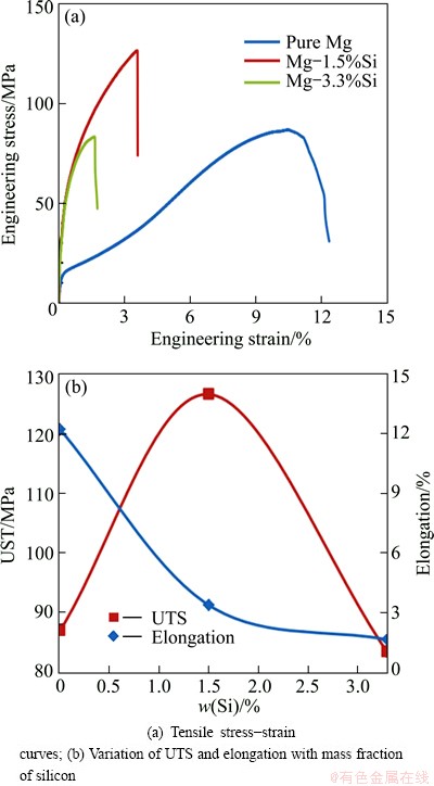
Fig. 8 Room temperature tensile properties of pure Mg, as-cast Mg-1.5%Si and Mg-3.3%Si alloys
Room temperature tensile stress��strain curves of Mg-1.5%Si alloy before and after 1 and 5 CCDF processes at 450 ��C are shown in Fig. 9(a). Variation of UTS and elongation with pass number is correspondingly plotted in Fig. 9(b). The as-cast Mg-1.5%Si alloy exhibits a tensile strength of 127 MPa and an elongation of 3.4%. With CCDF processing, both strength and ductility almost linearly increase with the increasing number of passes. After 5 passes, the elongation reaches 7.7%, which is twice that of the as-cast sample, and the tensile strength is 145 MPa, up to 14% more than the initial alloy. From the trend of microstructural evolution of Mg-3.3%Si in Fig. 4, CCDF not only breaks Mg2Si particle size but also improves the bond strength of Mg2Si and Mg interface. Both small Mg2Si particle size and good interface strength may improve the tensile strength and ductility of Mg-1.5%Si alloy. In this sense, the present findings are consistent with the general recognition that the CCDF process is an effective grain refining and strengthening method for magnesium alloys.
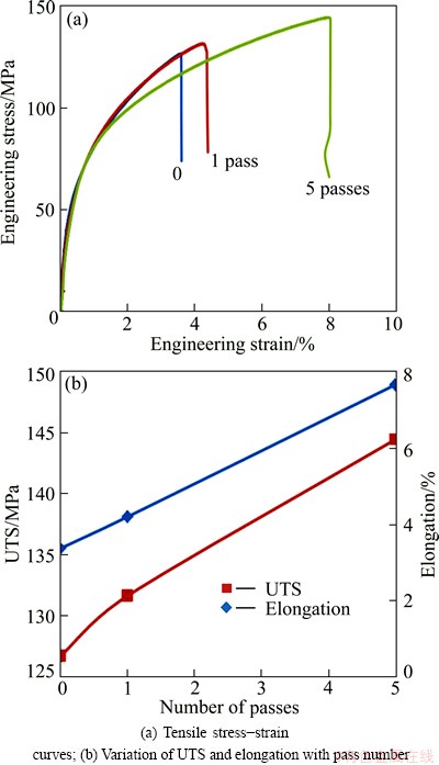
Fig. 9 Room temperature tensile properties of Mg-1.5%Si alloy processed by CCDF at 450 ��C
The addition of silicon reduces the elongation, but increases the tensile strength if silicon is added in good proportions. Moreover, CCDF, a severe plastic deformation process, increases both strength and elongation for the Mg-1.5%Si. Therefore, the most efficient way to improve both tensile strength and elongation seems to add a small amount of silicon to pure Mg, as for Mg-1.5%Si for example, and refine with CCDF process to get a homogeneously fine structure.
3.4 Wear resistance
The effect of the sliding speed on wear mass loss is shown on Fig. 10 at applied load of 10 N, temperature of 25 ��C, and 2000 m sliding distance. Figure 10(a) shows the effect of silicon addition after 5 passes by CCDF processing at two different sliding speeds. The wear mass loss is smaller at 120 r/min (translational speed around 0.12 m/s) than at 60 r/min (0.06 m/s) for all three alloys. Since the sliding speed is high, the decreasing in wear loss with sliding speed is not related to the transition from static friction to kinematic friction. In our apparatus, the wear counter material steel ball is easy to bounce away from the surface at higher speeds such as 300 r/min or above. Essentially, similar to roughness
measurement with a stylus profiler, sliding speed is an important factor to maintain proper contact between the counter ball and the Mg-Si wear surface. At 60 r/min better conformal contact is achieved compared with 120 r/min [27,28]. Therefore, higher sliding speed may lead to higher apparent roughness or lower friction coefficient, and further decreases wear loss rate. For Mg-1.5%Si alloy after 5 passes, the mass loss is 36.88 mg at 60 r/min for 2000 m sliding distance corresponding to 33333 revolutions. Each cycle back and forward removes around 11.1��10-4 mg. At 120 r/min the mass loss is 30.1 mg, or each cycle the material removal is 9.03��10-4 mg. The wear loss rate increases by about 1.23 times after dropping the sliding speed by 50%. At a sliding speed of 120 r/min, the wear mass loss is not sensitive to all three alloys, about 30.5 mg, and indicates that the roughness plays a major role in the wear rate at high speeds.
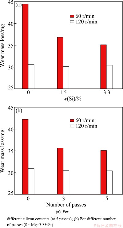
Fig. 10 Effect of sliding speed on wear mass loss
At a sliding speed of 60 r/min, the wear mass loss is reduced significantly from 44.5 mg to 36.88 mg with the addition of 1.5% silicon, and further decreases down to 35.13 mg with the addition of 3.3% silicon. Figure 10(b) shows the effect of the pass number on Mg-3.3%Si alloy at two different sliding speeds. At the speed of 120 r/min, the effect of the pass number on wear mass loss is not obvious and the wear loss only slightly decreases from 30.9 to 30.4 mg. Nevertheless, at a speed of 60 r/min, the wear mass loss drops from 42.2 to 35.6 mg after 1 CCDF pass. After 5 passes, the wear mass loss has diminished to 35.13 mg, although the significant improvement in wear resistance occurs after the first pass of CCDF [22]. The wear mass loss reduces by 15.6% at the first pass, whereas from 1 pass to 5 passes the reduction is only 1.3%.
The wear behaviors of pure Mg, Mg-1.5%Si and Mg-3.3%Si at sliding speed of 60 r/min before and after 1 and 5 passes are shown on Fig. 11. Since the effect of silicon addition and number of passes is more significant at low sliding speeds, wear rate measurement is studied under the following conditions: the sliding speed of 60 r/min, the applied load of 10 N, the temperature of 25 ��C, and the sliding distance of 2000 m. The addition of 1.5% or 3.3% silicon to pure Mg improves drastically its wear resistance due to Mg2Si hard particles [29]. For the as-cast alloys the wear loss decreases from 46.22 mg for pure Mg to 42.20 mg for both Mg-1.5%Si and Mg-3.3%Si alloys. After 1 pass of CCDF processing, the improvement in wear resistance is even more significant. The wear mass loss is reduced from 45.87 mg for pure Mg to 35.60 mg for Mg-3.3%Si. The wear resistance of Mg-3.3%Si is little superior to that of Mg-1.5%Si, but this is not significant with regards to pure Mg. After 5 passes, the wear mass loss continues to decrease for all three alloys, but only slightly. The addition of silicon decreases the mass loss and improves wear resistance for both as-cast and CCDF processed alloys. These results of wear loss rate may be related to hardness using the Archard wear equation:
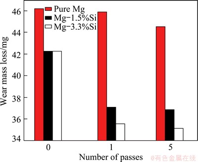
Fig. 11 Wear mass loss of pure Mg, Mg-1.5%Si and Mg-3.3%Si before and after 1 and 5 passes at sliding speed of 0.06 m/s, applied load of 10 N and temperature of 25 ��C with 2000 m sliding distance
 (1)
(1)
where Q is the wear loss rate, K is the dimensionless constant, p is the total normal load, H is the hardness of the surface containing softer phase, and L is the sliding distance. The addition of silicon significantly increases hardness, which is consistent with the decrease of wear mass loss based on Eq. (1). To fix parameters such as external load and sliding distance makes easier to study the wear loss rate from the effect of material and CCDF processing. The CCDF process also increases hardness after 3 and 5 passes, as the wear mass loss decreases, especially for pure Mg and Mg-3.3%Si alloy.
The increase of wear resistance with CCDF process may be understood from the aspect of microstructure refinement and homogenization of Mg-Si alloys. Mg-3.3%Si exhibits coarse Mg2Si particles initially, and a relatively homogeneous microstructure after 5 passes of CCDF. Mg-3.3%Si alloy also has a better wear resistance after 5 passes of CCDF than that in the initial as-cast condition. This shows narrower width and smaller depth of its wear mark. The arc length of the wear mark is 2485 ��m for the as-cast alloy and 2180 ��m after 5 CCDF passes. The average Mg2Si particle size also decreases from 33 to 13.6 ��m after CCDF. From the Mg2Si particle size and wear mark length, there are about 6 Mg2Si particles for the as-cast alloy and 13 particles for the 5 passes CCDF processed Mg-3.3%Si alloys, respectively. In the latter, although the Mg2Si particle size is smaller, the distance between particles is smaller, about 11 ��m, compared with as-cast alloy, about 26.7 ��m. During the wear test, soft pure Mg matrix among hard Mg2Si particles is subjected to less constraint from particles for the as-cast alloy and is easily removed by the pin, which leads to higher wear mass loss. For Mg-3.3%Si processed by 5 passes of CCDF, the distance between hard coarse Mg2Si particles is smaller and the pin is supported by more Mg2Si hard particles. Thus, a small amount of matter is taken off and the wear resistance is better compared with the as-cast alloy.
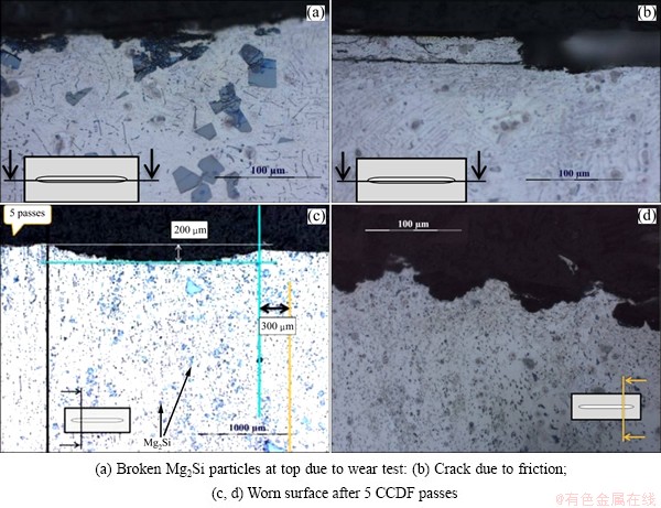
Fig. 12 Microstructures of as-cast Mg-3.3%Si alloy
Microstructures of as-cast and 5 passes CCDFed Mg-3.3%Si alloys after wear test are shown in Fig. 12. The abrasion surface is indicated in the figure. Figure 12(a) shows that Mg2Si particles near the surface have been broken during the wear test under the applied force of 10 N. Below 50 ��m from the surface, all the Mg2Si particles are totally broken, but below 100 ��m from the surface, few Mg2Si particles are broken. The effect of the wear test on the microstructure is limited to the surface. The normal external load 10 N itself (estimated around 10 MPa for 6 mm steel ball) is not able to facture Mg2Si particles under compressive loading. The Mg2Si particles are subjected to high cyclic lateral shear stress from frictional loading during wear test since soft Mg matrix is not able to equally partition load. The Mg-Si alloy below 100 ��m is less subjected to cyclic lateral shear stress due to limited elongation (<8%). The worn surface exhibits lateral cracks on the surface, as shown in Fig. 12(b). The cracks propagate along horizontal direction, indicating a fatigue wear mode. The relatively brittle Mg-Si material during the wear test is subjected to cyclic loading due to friction, and the fatigue wear creates cracks in the surface layer or on the surface, resulting in delamination. The thickness of the layer in Fig. 12(b) is around 20 ��m. The surface is still not totally delaminated and remains linked to the surface until the crack is big enough to extend into the surface. This shows that 10 N may be a high load for the alloys studied here. The worn surfaces of the Mg-3.3%Si alloy after 5 CCDF passes are shown in Figs. 12(c) and (d). This indicates that few Mg2Si particles near the surface is broken during the wear test, due to the fact that their size is remarkably refined and their distribution is homogenized by CCDF. In addition, no lateral cracks are detected on the worn surface of alloy after 5 passes, which indicates that fatigue wear resistance of Mg-3.3%Si alloy is improved by CCDF.
4 Conclusions
1) The CCDF process can refine and homogenize Mg2Si particle size and morphology. In the Mg-3.3%Si alloy, after 5 passes, the initially large dendritic structure, coarse particles or bar of eutectic of Mg2Si break up into many finer particles with uniform distribution in matrix. Average grain size of Mg2Si particles gradually decreases with the increase of pass number from 41.0 to 19.7 ��m.
2) The addition of silicon and the grain refinement by CCDF processing improve the harness. Both strength and ductility of the Mg-Si alloys increase significantly with the increasing CCDF passes number.
3) Mg-1.5%Si alloy exhibits a combination of improved strength and elongation after 5 passes of CCDF processing. The tensile strength is about 142 MPa and elongation is about 8%.
4) The addition of silicon and the number of CCDF passes, particularly the first pass of CCDF, improve wear resistance measured from wear mass loss. The improvement of wear is related to microstructure refinement and homogenization based on the Archard equation and friction effect.
References
[1] MORDIKE B L, EBERT T. Magnesium: Properties-applications- potential [J]. Materials Science and Engineering A, 2001, 302: 37-45.
[2] LUO A A. Recent magnesium alloy development for automotive powertrain applications [J]. Materials Science Forum, 2003, 419-422: 57-66
[3] HUANG W, HOU B, PANG Y, ZHOU Z. Fretting wear behavior of AZ91D and AM60B magnesium alloys [J]. Wear, 2006, 260: 1173-1178.
[4] AN J, LI R G, LU Y, CHEN C M, XU Y, CHEN X, WANG L M. Dry sliding wear behavior of magnesium alloys [J]. Wear, 2008, 265: 97-104.
[5] AUNG N N, ZHOU W, LIM L E N. Wear behaviour of AZ91D alloy at low sliding speeds [J]. Wear, 2008, 265: 780-786.
[6] SHARMA S C, ANAND B, KRISHNA M. Evaluation of sliding wear behaviour of feldspar particle-reinforced magnesium alloy composites [J]. Wear, 2000, 241: 33-40.
[7] LIM C Y H, LEO D K, ANG J J S, GUPTA M. Wear of magnesium composites reinforced with nano-sized alumina particulates [J]. Wear, 2005, 259: 620-625.
[8] NGUYEN Q B, GUPTA M. Enhancing compressive response of AZ31B magnesium alloy using alumina nanoparticulates [J]. Composites Science and Technology, 2008, 68: 2185-2192.
[9] WANG X J, HU X S, WU K, DENG K K, GAN W M, WANG C Y, ZHENG M Y. Hot deformation behavior of SiCp/AZ91 magnesium matrix composite fabricated by stir casting [J]. Materials Science and Engineering A, 2008, 492: 481-485.
[10] LU L, LAI M O, HOE M L. Formaton of nanocrystalline Mg2Si and Mg2Si dispersion strengthened Mg-Al alloy by mechanical alloying [J]. Nanostructured Materials, 1998, 10: 551-563.
[11] ZHANG J, FAN Z, WANG Y Q, ZHOU B L. Microstructural development of Al-15wt.%Mg2Si in situ composite with mischmetal addition [J]. Materials Science and Engineering A, 2000, 281: 104-112.
[12] YUAN G Y, LIU Z L, WANG Q D, DING W J. Microstructure refinement of Mg�CAl�CZn�CSi alloys [J]. Materials Letters, 2002, 56: 53-58.
[13] MABUCHI M, KUBOTA K, HIGASHI K. Tensile strength, ductility and fracture of magnesium-silicon alloys [J]. Journal of Materials Science, 1996, 31: 1529-1535.
[14] YAMASHITA A, HORITA Z, LANGDON T G. Improving the mechanical properties of magnesium and a magnesium alloy through severe plastic deformation [J]. Materials Science and Engineering A, 2001, 300: 142-147.
[15] MABUCHI M, HIGASHI K. Strengthening mechanisms of Mg-Si alloys [J]. Acta Materialia, 1996, 44: 4611-4618.
[16] VALIEV R Z, LANGDON T G. Principles of equal-channel angular pressing as a processing tool for grain refinement [J]. Progress in Materials Science, 2006, 51: 881-981.
[17] FENG Xiao-ming, AI Tao-tao. Microstructure evolution and mechanical behavior of AZ31 Mg alloy processed by equal-channel angular pressing [J]. Transactions of Nonferrous Metals Society of China, 2009, 19(2): 293-298.
[18] ZHAN Mei-yan, LI Yuan-yuan, CHEN Wei-ping. Improving mechanical properties of Mg-Al-Zn alloy sheets through accumulative roll-bonding [J]. Transactions of Nonferrous Metals Society of China, 2008, 18(2): 309-314.
[19] LIU Man-ping, ROVEN H J, LIU Xin-tao, MURASHKIN M, VALIEV R Z, UNGAR T, BALOGH L. Special nanostructures in Al-Mg alloys subjected to high pressure torsion [J]. Transactions of Nonferrous Metals Society of China, 2010, 20(11): 2051-2056.
[20] GUO W, WANG Q D, YE B, LI X C, LIU X T, ZHOU H. Microstructural refinement and homogenization of Mg�CSiC nanocomposites by cyclic extrusion compression [J]. Materials Science and Engineering A, 2012, 556: 267-270.
[21] NIE K B, WU K, WANG X J, DENG K K, WU Y W, ZHENG M Y. Multidirectional forging of magnesium matrix composites: Effect on microstructures and tensile properties [J]. Materials Science and Engineering A, 2010,527: 7364-7368.
[22] SU Y L, KAO W H. Improvement of the wear behavior of stircast Al-Si-Pb alloys by hot extrusion [J]. Tribology International, 2003, 36: 25-34.
[23] ZHANG Z M, XU C J, GUO X F, JIA S Z. Reciprocating extrusion of in situ Mg2Si reinforced Mg-Al based composite [J]. Acta Metallurgica Sinica: English Letters, 2008, 21: 169-177.
[24] GUO W, WANG Q D, LIU M P, PENG T, LIU X T, ZHOU H. Microstructure and mechanical performance of AZ31-1.7wt.% Si alloy processed by cyclic channel die compression [J]. Materials Science Forum, 2011, 667-669: 457-462.
[25] GUO W, WANG Q D, YE B, ZHOU H. Enhanced microstructure homogeneity and mechanical properties of AZ31-Si composite by cyclic closed-die forging [J]. Journal of Alloys and Compounds, 2013, 552: 409-417.
[26] EDDAHBI M, VALLE J A D,  M T, RUANO O A. Comparison of the microstructure and thermal stability of an AZ31 alloy processed by ECAP and large strain hot rolling [J]. Materials Science and Engineering A, 2005, 410-411: 308-311.
[27] HU M L, WANG Q D, CHEN C J, YIN D D, DING W J, JI Z S. Dry sliding wear behaviour of Mg�C10Gd�C3Y�C0.4Zr alloy [J]. Materials and Design, 2012, 42: 223-229.
[28] HU M L, WANG Q D, LI C, DING W J. Dry sliding wear behavior of cast Mg�C11Y�C5Gd�C2Zn magnesium alloy [J]. Transactions of Nonferrous Metals Society of China, 2012, 22: 1918-1923.
[29] HEKMAT-ARDAKAN A, LIU X, AJERSCH F, CHEN X G. Wear behaviour of hypereutectic Al�CSi�CCu�CMg casting alloys with variable Mg contents [J]. Wear, 2010, 269: 684-692.
J. METAYER 1, 2��Ҷ ��1, 3���� �1, 3��������1, 3���� �� 1,3��F. MOLLET1, 2
1. �Ϻ���ͨ��ѧ ��Ͻ��ܳ����ҹ����о�����, �Ϻ� 200240��
2. Arts et ParisTech engineering school, Angers, France;
3. �Ϻ���ͨ��ѧ ���������ϲ��Ϲ����ص�ʵ���ң��Ϻ� 200240
ժ Ҫ�������Ʊ�Mg-xSi (x=0, 1.5��3.3)�Ͻ��ٲ���һ���µĴ����Ա��η�������ѭ����ʽģ��(CCDF)��450 ��C����1��3��5���μӹ���ͨ��ѭ����ʽģ�ͣ��ִ��Mg2Si�����������С�鲢�ҷֲ����Ӿ��ȣ����ϵ�����ǿ�ȡ��쳤�ʺ�Ӳ�ȵõ�����ߡ���5���μӹ���Mg-1.5%Si�Ͻ��ǿ�Ⱥ��쳤��ͬʱ�õ���ߣ�����ǿ�ȴ�142 MPa���쳤��Ϊ8%�����øɻ���Ħ����һ�������������ܡ��������������Si�����ͼӹ����ε����ӣ����ϵ���ĥ���ܵõ�����ߣ��ӹ�1���κ�������ߣ��ټ������ӵ���ʱ��߲����ԡ���5���μӹ���Mg-3.3%Si�Ͻ����ĥ�Աȴ�þ�ĸ�38%������Archard���̺�Ħ��Ч������ĥ�Ե���߹������֯��ϸ���;��Ȼ���
�ؼ��ʣ�þ�Ͻ�Mg2Si��ѭ����ʽģ�ͣ�ĥ����֯
(Edited by Xiang-qun LI)
Foundation item: Projects (50674067, 51074106) supported by the National Natural Science Foundation of China; Project (2011BAE22B01-5) supported by the National Key Technologies R&D Program during the 12th Five-Year Plan Period, China; Project (09JC1408200) supported by the Science and Technology Commission of Shanghai Municipality, China
Corresponding author: Qu-dong WANG; Tel: +86-21-54742715; E-mail: wangqudong@sjtu.edu.cn
DOI: 10.1016/S1003-6326(14)63029-6

